3
System Specifications
Figure 1. Specifications
US Water Systems classifies each softener according to the actual resin capacity. However, this is not the
regeneration capacity. The regeneration capacity will be lower than the actual resin capacity. This is due to
the resin ’ s regeneration salt curve. For example:
A 53,000 grain unit would require 30 lbs of salt during regeneration if the capacity was set to the actual resin
capacity ( 53,000 grains ) . If the unit is set at 37,000 grains it can be regenerated using only 10 lbs of salt.
The unit is much more efficient when it is set using the proper salt curve capacity and salt dosage levels. So
you can see that to get the final 16,000 grains from a 53,000 grain unit the salt usage will more than double.
Please use the chart below when setting you softener. This will ensure efficiency and longevity of your unit.
Maximum Water Temperature = 110°F (43°C)
Maximum Operating Pressure = 100
PSIG (689 kPa)
Voltage = 110 volts standard
Pipe Size = 3/4”
At the stated service flow rates, the pres-
sure drop through these devices will not
exceed 15 psig.
Changing salt settings from factory setting
may require changing injector sizes to
achieve stated capacities.
The manufacturer reserves the right to make
product improvements which may deviate from
the specifications and descriptions stated herein,
without obligation to change previously manufac-
tured products or to note the change.
Model # System Capacity Grains Flow Rate Regeneration Water Mineral
Tank
Size
Resin
Cu. Ft.
Brine Tank/
Cabinet
Size Inches
Salt
Capacity
(Lbs)
Ship
Weight
(Lbs)
@ 10
lbs/cu ft
@6 lbs/
cu ft
(Factory
Settings)
@ 3 lbs/
cu ft
Service
USGPM
Back-
wash
USGPM
Clean
Water
(Factory
Setting)
Problem
Water
085-MX-100 25,000 20,000 13,000 10.0 2.0 38.0 48.0 9 X 48 1.00 15 X 15 X
34.7
230 122
085-MX-150 37,000 30,000 18,000 12.0 2.4 48.5 60.5 10 X 54 1.50 15 X 15 X
34.7
230 155
085-MX-200 50,000 40,000 25,000 15.0 3.5 80.5 95.5 12 X 52 2.00 20.3 X 37.4 385 158
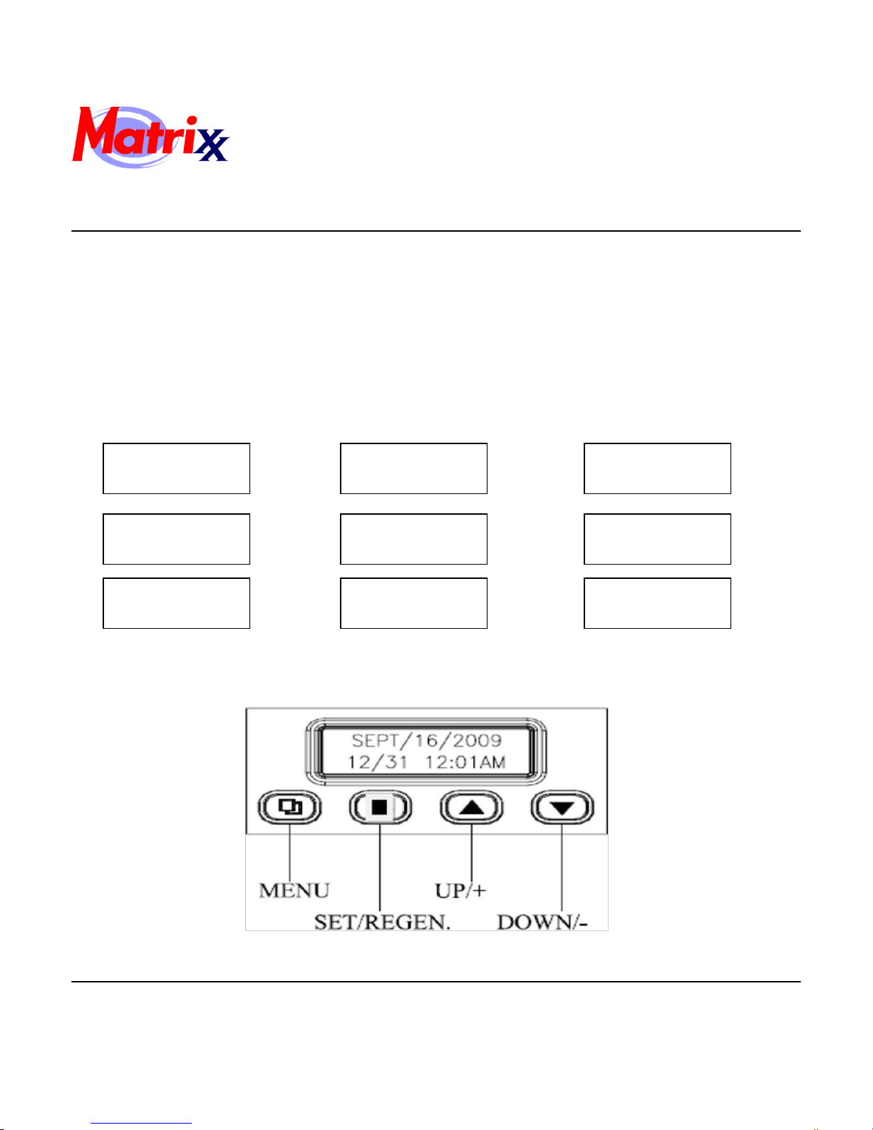
Installation, Operation and Maintenance Manual
Matrixx MX-100, MX-150, MX-200 System
For the HTO systems use the following chart.
24,000 37,000 44,000
4.7 7.1 9.5