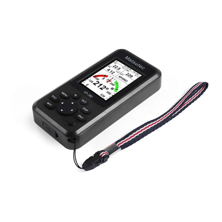
Matsutec HP-33 User manual

Matsut(ec'
MARINE GPS/SBAS NAVIGATOR
HP.33

Do not open the equipment.
Only qualified personnel should work
inside the equipment.
Do not disassemble or modify the
equipment.
Fire,electrical shock or serious injury can
result.
lmmediately turn off the power at the
switchboard if the equipment is
emitting smoke or fire.
Continued use of the equipment can
cause fire or electrical shock.Contact a
Matsutec agent for service.
Use the proper fuse.
Use of a wrong fuse can damage the
equipment or cause fire.
899u1e the power supply is compatible
with the equipment.
lncorrect power supply may cause the
equipment to overheat.
The useable temperature range for the
antenna unit is -25C to Z0C; -15C to
55C for the display unit.
Use of the equipment out of those
ranges may damage the equipment.

Do not open the cover unless totally
i*ili"t with electrical circuits and
service manual.
lmproper handling can result in electrical
shock.
Turn off the power at the switchboard
before beginning the installation'
Fire or electrical shock can result if the
power is left on.
Be sure that the Power suPP|Y is
compatible with the voltage rating ot tne
equipment.
Connection of an incorrect power supply
can cause fire or equiPment
damage.The voltage rating of the
equipment appears on the label above
the power connector.
Use the ProPer fuse.
Use of a wrong fuse can damage the
eqpipment or cause fire'
Obacrt te fttofrg conrPass s af e
OiitatuO fr:rrr rerftrence to a
magn:ficcoP
Slmdrd
ilnN Steering
compass
Displa!,
unit Ofilm 0.55 m

TABLE OF CONTENTS
1.
ilt

TABLE OF CONTENTS
5.2.2 How to set a destination waypritftoqgh tte 1ist......... ............5-2
5.3 How to Set Route as Destination..-.....--..---.- ......................5-2
5.4 How to Cancel Destination.. .......5-3
' 5.4.1 How to cancel destination vyith fE cus(r-------.- .....5-3
5.4.2 How to cancel destination throrrgtr fie Isi--------- .....5-4
6. ALARMS ...........6-1
7-1
8. MAINTENANCE, TROUBLESHOOT!NG...... 8-1
INDEX
iv
tN-1

FOREWORD
A Word to the Owner of the Hp_33
Ogatlatons on your choice of the Hp_33 GpS Navigator.
fuover 10 years Matsutec has enjoyed an enviabre reputation for innovative
td @endabte marine electronics is furthereo by our extensive global network of agents and
d"alerc.
Yurnavigator is designed and constructed to meet.the rigorous demands of the marine environ-
-r1 tlowever, no machine can perform its intended funJtion ,nr"., installed, operated and
Ei&tined properlv. Please careiurv ,."rd ;;J;br; il;#ffinded procedures for instara_
fur, operation and maintenance.
ubm,H appreciate feedback from you, the end-user, about where we are achieving our
lrrposes.
lnak you for considering and purchasing Matsutec equipment.
Fefrrres
II- min.features of the Hp_33 are as shown below.
' *ftfi-resolution color LCD,4'3"sunlight viewable color LCD GoTo track navigation
- WAAS capability
' $rage for 10,000 waypoints, 100 routes and 3,000 track points
' Alrrrs: Anivar/Anchor, XTE (cross-track Error), Trip, odometer, Time, wAuAS and Speed
' lkl overboard feature records position at time of man overboard and provides continuous up-
d*s of range and bearing when n"rigrti;;i;;; ;dilffi;:
: ll*nre Highway display provides a graphic presentation of boat,s progress toward a waypoint.
' lJserarogrammabre nav data disprays provide anarog and digitar navigation data.
' ilavigation data output to the autopilot when connecting.
' uYaypoint and route data can be uploaded from a pc and downloaded to a pc.

SYSTEM CONFIGURATION
Antenna Unit
HA-017 Nt{8A0183 devices
Radar
Video Plotter
Edro Sounder
AutoPilot
[Bfftmilts
etc
12-24VDC
l
I
t_
l-

1. OPERATIONAL OVERVIEW
1.1 Controls
-o.pens the Menu. (ptotter g1d highwav offi
-Shows the zoom window (ptotteland iigh;i"iiirpr"y;;;fi: - '*,
o
(Cursorpad
-Shifts the cursor.(up, down, left, right)
-Selects item on menus.
-Long press: Turns power off.(3 seconds)
-Momentary press: Turns power on./Shows Brill window.
-Long press: lnscribes MOB mark.
-Momentary press: Registers own boat position as MOB position.
-Long press: Returns own boat position to@
-Momentary press: Confirms selection ";;;;;"

How to detach the hard cover from the unit
Putyourthumbsonthefrontandforefingersonthecatchesatthesidesofthecover,
il1JJ'[:,",I;::'[l; *" GPS navigator ror rons period'prs keep cover the
screen to avoid screen damage'
1.2 How to Turn Power On'O'tr
1. press the o Bntuu kev to t,l Ttr"ror' The unit beeps and then starts up
withtherast-usedil;;r,,,."*jlT.Il5afr*trJ:ii.:ffiti-T#'
*n:tr;X:S'iim'ffi[im;; indication s and the i r
meanings'
Catches
2.
;"?3I,9,1'JlT:"1#i:l::L;rri'l.$i:*^"r"9'Jl"#:"J'iH'fHlbution pattem of s3fellites useo rn Puurtt\,I "^";;n.i;Op,'pOOp' Position DOP)
,*i"{"itn" position accuracy' (HDOP: Hori;
To turn off the power, press and h"|d :::1,t1?||'T:i:.-:l*T
lii1',HT,,T:[?ff 1"1',1i:r"-l:yT^i'il[Hfi5'"::]ft :iiT$::Iil;
H:Xffi ,liffi ,iil3r"Tr'il:-ilHffi ffi ff ;il-"ro*gsecondsto'rseconds
i.
i:'
&,;
s{
ffi
ffi
2D GPS Position frxed
SO CPS Position frxed
io wnns Position fixed
3D wms Gition fxed
ZO, ffOOP larger than 4
3D: PDOP larger than ti
Simulation mode
1-2
and then Power off'

1.3
1.4
1. OPEMTIONAL OVERVIEW
How to Adjust LGD and Key panel Brilliance
1. Press the O /BruLL key to show the following window.
ErilI
LCD { ttin llax F
{ l-------t
IilY 7 fiin Hax I
3 t------l
2.
3.
4.
To adjust the LCD briiliance, pr""" O /BRILL key.
The setting changes "0-->1-+...-+7-6..^Oj..." iontinuousry. Maximum setting
is 7. You can use atso the cursorpad f J >l i" adjust the briiliance.
To adjust the panel brilliance, press the cursorpad (A, V, max: T).
Press ENT or MENU/ZOOM key. to choose and return back other menu.
Display Modes
[1]: Plotter disptay
The unit has seven dispray modes: protter Dispray, Highway Dispray, steering Dis_
play, Nav Data Dispray, sateflite rr,|onitoioi"pray and User Dispray ,1/2. press the
DISP key to serect a dispray mode. Each tim! tne key is pressJo,ine oisptay mode
will change in sequence shown berow r" "i"p through the disprays in a reverse order,press the DlSp key more than three secondJ
o
loge I
ft rml
0.10
Grt cBRG *] I
n1
2Q2
nXG lnml
0_03
SG 4'3e?6.1.E1. 0,012
[2]: Highway disptay
'.0 . .J\ t*zd,
-10 70
..-o sG(h)
. 20.0.,__Y n1.s18.8\
[6]: User disptay 1
3Dk * 03:37:a
ffi
64'
- 64"
sG 20.0, fcmu
RxG 0.68,. mil
nc 00H 02il I ET; Pf,
ss 20.05 lcrcr 64'
[4]: Nav Oata Oisptay
t@
rD,f "-'\ mp
I
@-, / =\ r'si-
ftP , = _E 1 --<
'. _-{ P r--
l\E / ,
r156n \-,d/ ;:
1-3
31' a-
v,! oE.a
2236'18.8"r tt*"gSSS.i;.
30 zlJ. t&t3 Jms _l
2236'12.7"i1
11439,25.g"e I
,';; ld,
[5]: Satettite Monitor disptay

1. OPEMTIONAL OVERVIEW
Plotter Disolay
The plotter display can trace own boati s track, Please see below Picture'
Cursor
Wavooint mark .
(Sha'Pe selectabte) (displaYed for aPProx'
seven seconds) I
Own boat mark
Receiver status Course bar
Horizontal disPlaY
range scale
Range to cursor*
Bearing to cursor*
Cursor Position
(When cursor rs nor displayed'it will display own boafs position')
* :coG and s-oc- r"g1m ?i?sJfl J".3t ti3[,?]30
range to cursor wnen
i14

1. OPEMTIONAL OVERVIEW
Hbhway Display
The highway display provides a 3-D view of own boat toward the destination.
{IE (Crosstrack error) scale and arrow mark
Anow shifts with boat's XTE. When the arrow
is aligned with the center line the boat is on
course. The arrow blinks if boat's XTE is
greater than XTE scale range.
"N (North)" is displayed, instead of the arrow,
at the center of the scale when no destination
is set.
Bearing from
own boat to
destination
waypoint
Speed
over
ground
Direction to steer
(to return to course)
Steer right. l: Steer left.
Destination
waypoint name
Course
over
ground
Current
position DigitalXTE indication
(in nautical miles)
Own boat mark
The boat mark displays course as follows:
When no waypoint is set;
The mode is North-up and
the arrow shows boat's course.
When a waypoint is set;
The arrow shows boat's
cou rse towards destination.
Range from own
boat to destination
waypoint
SOG (knll 2236'23.4"xtXTE
20.0 t{4"39'46.1"e D
"g6,23.4"piXTE {nml
"39'46.1"s D 0.01 2

1. OPEMTIONAL OVERVIEW
Steerinq Disolay
The steering display provides steering information as below'
Speed
over ground
Receiver status Bearino reference;
MAG(n%ti;) oiinue rime
Time-To-Go
to destination
Ranoe from
ownboat to
destination
Nav Data Disolay
Estimated Time of
Anival at destination
destination
Bearing scale
Own boat mark
Course over ground
Bearing to
the destination
Date and time
Position in latitude
and longitude
Course over ground
3D nAG ,q* Ff* 03:37;28
soc 20.0 m rcoc u
RNc 0,68 n, BRG rl
m OOuOenr I ETA ,'l'efrl||
3'D 27lJanl2013 PH 03:38:22
22"36'12,7"H
114039'25,8"E
20.0 rn I coc H
Speed over ground
1-6

1. OPERATIONAL OVERVIEW
Satellite Monitor Display
The satellite monitor display shows the status of GPS and GEO satellites.
Number, bearing and elevation angle of all GPS and GEO satellites (if applicable) in
view of your receiver appear.
Elevation
45"
DOP value
Receiver
siqnal level
Bars show
signal level.
Satellites
whose signal
level are high
are used in
fixing position.
Area not used
for positioning
(set at menu)
Satellite numbers in
reverse video are
used for positioning.
User Disolav 1. User Displav 2
. Digitaldisplay
The digital display shows digital navigation data. You can select what data to dis-
play from one to four cells. The choices of data are time, date, speed over ground,
cross-track-error, odometer distance, position, course over ground, time-to-go to
destination, trip distance, power source voltage, range and bearing to waypoint and
estimated time of arrival at destination.
. Speedometer display
The speedometer display provides both digital and analog displays of speed over
ground.
. COG display
The COG display shows both analog course over ground, and digital speed over
ground.
f,':o u, .,i\ '*^.:l''
f **\_1
-o soc(h) eo-'/,fi:i!,ii!:;
( 20.0 /
{33oiA\
. ioo "*',., 30 '
- svv coc [f)
soc {t.}
w '20,a 60
COG display
Sample digitaldisplay
(four cells) Speedometer display
(default: User display 1)
g
E
@
E
@
E
@
a
q
E
E
@
@
*.'-. -_:
-in-.* l
r*-***-**-J
rrIIf-1
r::-.-.*-l
rrII[l
rr,-=I*I
rrllfl
rrIflI
rrlf-l
-I-- I
tr=l----,-]
rrII[]
rril'_l
t6 lsoc (b)
,fiI3:?3:3:: | 20.0
e- rrtlxrr tnm)
296 <- o.oo7
User display 2)

1. OPERATIONAL OVERVIEW
1.5 Menu Overview
Most operations of your unit are operated through the menu' Below is a quick introduction
to how to select a menu and change menu settings. lf you get lost in operation, press
. the MENU/ZOOM key to get back to the main menu'
l.PresstheMENUtzooMkeyonceortwicetodisplaythemainmenu.
Press once: Steering display, nav data display, satellite monitor disp|ay, user dis-
PlaY 112.
Press twice: Plotter display' highway display
Note:FollowingexplanationtakesthemenusfortheplotterdisplayaSanexam-
ple.
Ship Io Center*
Boutes
Plotter SetuP
Alarns
llessages
Delete
GPS SetuP
T,IAAS
rttffiE0]ll .C"rrt"lrB.* tElfl:Enter l/Y:Select
2.
3.
.' tn[.3il0,28'oWl'frsJf
diesseO at the Plotter disPlaY'
You can Press A or V to select an item, and press the ENT key,
Press ENT.
For example, select [Plotter Setup] and press the ENT key'
l1enu )Plotter SetuP
+i------+:-
Auto iragioint Entrg(CttGl tEil 60 " 10 s
C0G Line : 0n
C,G/B*G fef.. : llag
t'lqgrrEtic Uariatiarn : Auto ll 3 o
l,tf ilane ; llisP Goto
IIG/f,IA 6pD : Auto 60 s
Press A or V to select option desired'
For example, select ICOG/BRG ref']
Press the ENT keY '
A window shows the options for the item selected'
6. Press A or V to select option desired'
7. Press the ENT keY .
8. Press the MENU/ZOOM key twice to close the menu and return
4.
5.
l
1-8
back to main menu.

1.6
1. OPERATIONAL OVERVIEW
lbrb enbr alphanumeric data
Sane rnenu operations require you to enter alphanumeric data (A to Z, 0 to 9) and
silfiols (&, -, #,' , -, > and space). The procedure which follows shows how to enter
{hanumeric data. For example, to change the waypoint name 1WP0008" to "CNSZ",
dotp follows:
t) Press A or V to select "C".
2) Press ), and press A or V to select "N".
3) Press ), and press A or V to select "S".
4) Press ), and press A or V to select "Z".
5) Press ), and press A or V to select " "(space).
6) Press ), and press A or V to select " " (space).
7) Press the ENT key.
How to Enter the MOB Mark
Pbase be noted, only one MOB mark is displayed.
Each time the MOB mark is entered the previous MOB mark and its position data are
ovenrriften.
1. Press and hold the WPT/MOB key down to show the following message.
Eoto ilIIE ?
EHo
2. To set MOB position as destination, press [Yes] to choose and press the
ENT key. MOB mark ("M") appears and a blue line is drawn between own boat
mark and the MOB mark. This line shows the shortest course to go to the MOB
position, and arrows on the line show the direction to the MoB position.
1€

1. OPERATIONAL OVERVIEW
Shortest course from own
boatto MOB position (blue)
Bearing from own boatto MOB position
Range from'own boat to MOB position
MOB mark
(red)
1-10

PLOTTER DISPLAY OVERVIEW
l.l How to Select the Display Range
You can change the display range on the plotter and highway displays. The horizontal
range in the plotterdisplay is available among 0.02,0.05, 0.1,0.2,0.5,1,2,5, 10,20,
40, 80, 160 and 320 nautical miles. The horizontal range in the highway display is
available among 0.2,0.4,0.8,1,2,4, 8 and 16 nautical miles.
1. Press the MENU/ZOOM key on the plotter or highway display.
The following window appears.
t--^----]t--;---l
I o.son, ll o.znm I
l,o.o*Jo ,', ll ,..-I .,, I
(Plotter display) (Highway display)
2. Press A or V to select range you want.
3. Press the ENT key to choose and press MENU/ZOOM key to return back main menu
display.
How to Shift the Gursor
Use the cursorpad to shift the cursor. The cursor moves in the direction of the arrow
or diagonal.
Cursor state and oosition indication
The position indication, shown at bottom of the plotter display, changes according to
cursor state.
Cursor at rest
When the cursor is not shown, boat's position of longitude and latitude will appear
at the bottom of the display.
22
COG COG line
Own boat
Own boat's position
latitude and longitude
rlcourse over ground)
SOG
(speed over ground)
2-1

PLOTTER DISPLAY OVERVIEW
::XrT["":ff'l'J:'::;'l'Jndronsitudeatthebottomortheprotter
*'" :]] ::"*'ffi", ]llll""u" n second s' the cursor d i sappears
Range from-
own boat to Gursor
Bearing from
own boat to cursor
COG line
Own boafs marx
Cursor
f,,t[i3t%Ti'"3lJLuou
2,3 How to shift the Display av
-rn" O,**, can be shifted on the plotter display'
1. Press the cursorpad to show the cursor'
; ft*f: *lt*J1,*t** i' ffTil;"' the disprav shins in the direc
iion oPPosite to cursotl'ro" -'--
iH:::lffi [i:3:fl"ffi fl :IJfi;
liEl,[ ff ;'J ;lH;;" three seconds
l
L
\I
\
2-2

l- 2-3
2. PLOTTER DISPLAY OVERVIEW
2.1 How to Change The Track Plotting lnterval, Stop Re-
cording
To tace the boat's track, the boat's position is stored into the memory at an interval of
distance or according to display range. For example, a shorter interval provides better
reconstruction of the track, but the storage time of the track is shorten. When the track
memory becomes full, the oldest track is erased to make space for the latest. You can
Choose the [racks] on the menu to check the current percent of the memory used.
Press the MENU/ZOOM key twice to show the main menu.
Select [Tracks], and press the ENT key.
lleru )Tracks
nrc : liElEllllil0,01 nm
Color : Purple
Delete : Bg Color
Track llEnoru UsE.l 32
UtEtlU./2001'lI:Cancel./Eack IEllTl:Enter A/V :SelEt
3. Confirm that the [Rec] is selected, and press the ENT key.
Iff
fluto
Select [Off], [Distance] or [Auto], and press the ENT key.
Off: Track is not recorded. This setting is usefulwhen you do not need to record
track.
Distance: Track is recorded and plotted at the distance interval set.
Auto: Plotting and recording intervalchanges with display range selected.
For [Off] or [Auto], go to step 6. For [Distance], enter the recording interval as fol-
lows:
1) Press ).
2) Press ENT key.
3) Use the cursorpad to enter the interval, and press the ENT key.
For entering the numeric data, see page 1-9.
Press the MENU/ZOOM key twice to close the menu.
1.
2.
4.
Other Matsutec Marine GPS System manuals
Popular Marine GPS System manuals by other brands
Thrane&Thrane
Thrane&Thrane Explorer 727 installation manual

Garmin
Garmin GPSMAP 215 Owner's manual & reference

Iridium
Iridium GO! exec Faqs

Garmin
Garmin GPSMAP 3205 - Marine GPS Receiver Template manual

Raymarine
Raymarine axiom pro 9 RVX installation instructions

COBHAM
COBHAM AVIATOR UAV 200 installation manual