Matt:e VU-1-63-TP User manual

Electric Vehicle Charger
Connection Units
EVU-1-63x EVU-3-63x
EVU-1-32x EVU-3-32x
Installation Manual
V1.71 Mar 2021

EV Charger Connection Unit
2 | P a g e
Contents
Product escription 3
Warning Notice 3
Safety Advice 3
Introduction 4
imensions & Mounting the unit 5
Electrical Connections 6
Operating Instructions 10
Test Function 10
Specifications 11
Warranty 11
eclaration of Conformity 12
PRODUCT ADVISORY NOTICE
This product must be inst lled by competent person in
ccord nce with the IET Wiring Regul tions, BS7671 (18
th
Edition or l ter) nd current Building Regul tions.
Ensure the electric l supply is disconnected before inst ll tion
or removing the cover of the unit.

EV Charger Connection Unit
3 | P a g e
Once inst lled, the unit
h s Live M ins Supply (400
v or higher)
within the enclosure. The cover must not be removed until the
supply to the unit h s been isol ted or disconnected.
Product escription
The m tt:e Electric Vehicle Charger Connection Units (EVCCU) are
designed for use in commercial applications where 3 phase PME
supplies are feeding Electric Vehicle Chargers.
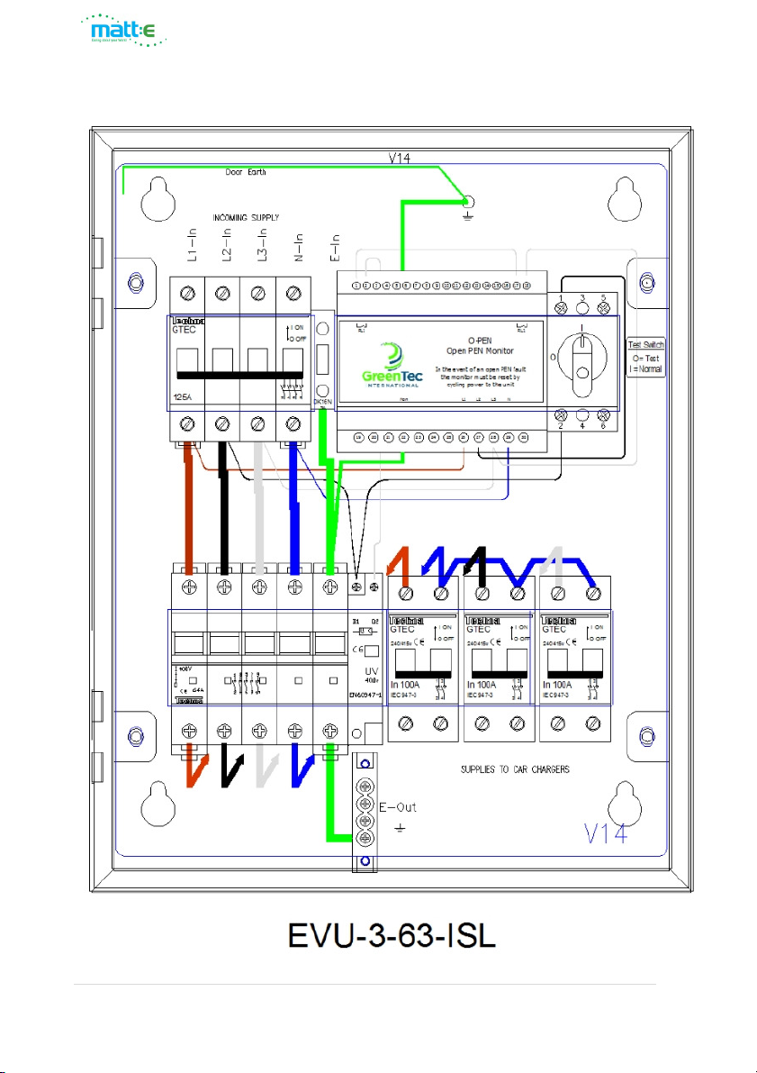
This manual covers the EVU-1-63-TP, EVU-3-63-ISL, EVU-1-32TP-R,
EVU-1-32TP-M, EVU-3-32-R & EVU-3-32-M units.
The units are not intended for any purpose other than that defined
within this document.
WARNINGS
Please read and observe the following notices carefully. These
warnings must be observed when installing and operating the Electric
Vehicle Charger Connection Units.
All relev nt supplies must be isol ted or disconnected before commencing
ny work. This product must be inst lled by competent person in
ccord nce with the IET Wiring Regul tions, BS7671 (18
th
Edition or l ter)
nd ny relev nt Building Regul tions nd/or Inst ll tion Regul tions.
S fety Advice
The unit must be inst lled in dry ventil ted loc tion; it must never be
covered or h ve restricted ventil tion.
The EVU-3-32-x nd EVU-1-32-x units re r ted for m ximum 32A.
The EVU-3-63-x nd EVU-1-63-x units re r ted for m ximum 63A.
For any information not contained within this document, please contact our
technical support team on 01543 227290 or info@matt-e.co.uk.

EV Charger Connection Unit
4 | P a g e
Introduction
The m tt:e range of Electric Vehicle Charger Connection Units are
fitted with O-PEN technology designed to protect Electric Vehicle
Charging equipment when installed onto 3 phase PME infrastructures.
The unit incorporates a 5 pole isolator with a built-in under-voltage
release mechanism. On detection of fault conditions the O-PEN
electronic circuit de-energises the under-voltage release mechanism
which disconnects all poles of the supply including CPC. The 5 pole
isolator is manually resettable in line with IET Wiring Regulations and
code of practice.
If the O-PEN monitor detects a fault and activates the isolator the
monitor must be reset by cycling power to the unit. It does NOT
automatically reset.
The m tt:e O-PEN technology does not require earth rods or measuring
electrodes to function correctly.
The units are designed to be installed indoors between the distribution
board and the Electric Vehicle Charger. The unit must be mounted
securely to a solid surface with the lid hinges on the left.
The inst ll tion loc tion should be cle n, dry nd well ventil ted.
Please refer to the diagrams on the following pages for the dimensions
and mounting arrangement of the units

EV Charger Connection Unit
5 | P a g e

EV Charger Connection Unit
6 | P a g e

EV Charger Connection Unit
7 | P a g e
Electrical Connections
The user wiring connections are indicated in the diagrams below.

EV Charger Connection Unit
8 | P a g e

EV Charger Connection Unit
9 | P a g e

EV Charger Connection Unit
10 | P a g e

EV Charger Connection Unit
11 | P a g e

EV Charger Connection Unit
12 | P a g e

EV Charger Connection Unit
13 | P a g e
Connect the incoming cable from the distribution board directly to the
4 pole isolator. The CPC should be connected to the terminal block
Connect the outgoing cable(s) to the MCB, RCBO or 5 pole isolator
depending on the unit being installed. The outgoing CPC should be
connected to the isolated earth bar except for the EVU-1-63-TP.
THIS PRODUCT IS DESIGNED FOR AN ISOLATED
EARTHING ARRANGEMENT. CHECK BEFORE USING
SWA CABLE
On completion of inst ll tion the tightness of ll electric l
connections should be checked before energising the unit.
See specific tions for tightening torques.

EV Charger Connection Unit
14 | P a g e
Alternative 230v UV release wiring.
Some units are fitted with a 230v Undervoltage release mechanism.
The internal wiring for this variation is shown below.

EV Charger Connection Unit
15 | P a g e
Operating Instructions
With the incoming isolator closed the unit will monitor the incoming
supply. Approximately 1 second after closing the incoming isolator the
O-PEN monitor will energise the under-voltage release mechanism of
the 5 pole isolator. At this point the 5 pole isolator can be closed to
connect the load to the incoming supply.
In the event the O-PEN unit detects a fault condition on the neutral of
the monitored supply for a period of 4 seconds the internal relays will
de-energise and remove the supply to the under-voltage release
mechanism of the 5 pole isolator. This will cause the 5 pole isolator to
open disconnecting all phases, neutral and CPC from the load.
After any fault condition is detected causing the monitor to enter a
tripped condition the monitor must be reset by cycling power to the
unit via the 4 pole incoming isolator
Test Function
A Test Switch is provided to allow the functionality of the
units to be checked. With the unit powered and the 5 pole
isolator closed rotate the Test Switch anti-clockwise to
position O to initiate a test. This will disconnect L1 from the O-PEN
monitor and create a fault condition. After 0.7 seconds the O-PEN
monitor will trip the 5 pole isolator by de-energising the under-voltage
release mechanism. We recommend the unit is tested on a 6 monthly
basis.

EV Charger Connection Unit
16 | P a g e
Specifications
Description Electric Vehicle Ch rger Connection Unit
Input (Volts) Nominal input voltage 400v, 50Hz, 3 Phase AC
M x Lo d EVU-x-32 32A | EVU-x-63 63A
Dimensions 380mm x 300mm x 120mm
Weight Approximately 7 kg
Oper ting Temp -5°C to +40°C
Enclosure Mild Steel Powder Coated
Power Consumption 12VA
Ingress Protection IP4X
Document Revision
V1.71 Mar 2021
Termin l C p cities Min Max
Incoming Isolator cable size &
tightening torque
2.5 mm
2
1.5Nm
25.0mm
2
2Nm
Outgoing MCB cable size &
tightening torque
2.5 mm
2
1.5Nm
25.0mm
2
2Nm
Outgoing RCBO cable size &
tightening torque
2.5 mm
2
1.5Nm
25.0mm
2
2Nm
Warranty
The EVCCU is guaranteed for a period of 1 year from the date of manufacture.
This warranty is limited to the replacement of faulty components only.
t: 01543 227290 e: info@matt-e.co.uk w: www.matt-e.co.uk
matt:e Ltd, Unit 5, Common Barn Farm, Tamworth Road, Lichfield WS14 9PX

EV Charger Connection Unit
17 | P a g e
EU Declaration of Conformity (DoC)
Ref : EVCC-32/63-2019
We
Company name: matt:e Ltd
Postal address: Unit 5 Common Barn Farm Tamworth Road
City Lichfield
Postcode: WS14 9PX
Telephone number: 01543-227290
Declare that this DoC is issued under the sole responsibility of the
manufacturer.
Apparatus model/Product: EVU-3-32 EVU-1-20 EVU-1-32 EVU-1-63
Type: EVCC
Object of the declaration
Electric Vehicle Charger
Connection units
E
VU
-
1
-
63
-
TP EVU
-
3
-
63
-
ISL EVU
-
1
-
32TP
-
M
EVU-3-32-R EVU-3-32-M EVU-1-32TP-R
The object of the declaration described above is in conformity with the relevant Union
harmonisation legislation:
Low Voltage Directive (2014/35/EU)
The following harmonised standards and technical specifications have been applied:
EN60255-1 2010 Emissions standard for Measuring Relays and Protection Equipment
EN55011 Class A 2011 + A1:2017 Emissions Standard for ISM Equipment
EN60255-26 2013 Immunity standard for Measuring Relays and Protection Equipment,
EN61000-4-2 2009 ESD Requirements
EN61000-4-3 2006 + A1 + A2 Radiated Susceptibility
EN61000-4-4 2012 Electrical Fast Transient Burst Requirement
EN61000-4-5 2006 Surges Requirements
EN61000-4-6 2009 Conducted Susceptibility
EN61000-4-11 2004 Voltage Dips and Interruptions
EN61439-1&2 2011 Low-voltage switchgear and controlgear assemblies.
EN60947-3 Low-voltage switchgear and controlgear
EN61095 Electromechanical contactors
EN61009-1 Residual current operated circuit-breakers with integral overcurrent
Signed for and on behalf of: matt:e Ltd
Place of issue Date J Charlton, Director
Lichfield, England 3 July 2019
This manual suits for next models
5
Table of contents
Other Matt:e Automobile Accessories manuals
Popular Automobile Accessories manuals by other brands

Front Runner
Front Runner RRAC051 quick start guide

Cruz
Cruz Evo Rack Alu A30-140 Assembly instructions

Rear view safety
Rear view safety RVS-912619P Product manual installation & instructions

ALAN Electronics
ALAN Electronics Albrecht BT 2000 operating manual

Whelen Engineering Company
Whelen Engineering Company ION installation guide

Well
Well JOY user manual