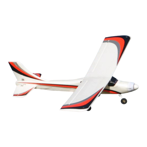
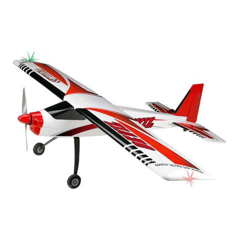
Max-Thrust Ruckus Balsa Pro-Build Series User manual

Instruction Manual

22
Warning:
This radio controlled model is not a toy. It requires skill to y and is not recommended for use by
beginners without assistance from an experienced model pilot. It should not be operated by children
without the supervision of a suitably experienced adult.
Max-Thrust reserves the right to modify the specication of this model at any time.
Safety Precautions
1. Do not attempt to repair or modify this aircraft with non-factory parts.
2. Never y this model over roads, railway lines, near to power lines, airports, do not y this model in
excessively strong winds, in the rain, or thunderstorms.
3. Do not y or launch the model towards people.
4. Keep hands and face away from rotating propeller at all times.
5. We strongly recommend that all xings and fasteners used in the construction of this model are
checked regularly for integrity. Failure to do so could cause a crash, injury to yourself or others around
you.
6. We only recommend the use of 2.4GHz radio equipment with this model.
Disclaimer
1. This radio controlled model is not a toy. Used incorrectly it is capable of inicting serious injury to
persons or damage to property. The owner/pilot assumes all responsibility for any damage to persons or
property resulting from the use of this product.
2. The manufacturer and distributor decline all responsibility for any liability arising from use of this
product.
3. It is very important that you follow all instructions for assembling and setting up of this model. Failure to
do so could result in a loss of control and possibly a crash
Statement

33
Tools:
Philips Screwdriver Medium
Philips Screwdriver Small
Modelling Knife and Spare Blades
3mm Allen Key
2mm Allen Key
30 Minute Epoxy Glue
Slow Cyanoacrylate Glue (Cyno)
Foam Padding
Items Required
Equipment:
1 x Transmitter and Receiver
5 x Standard or Small Servos IC version - 4 x Standard or Small Servos Electric Version
2 x 200mm Servo Extension Leads
1 x 200mm Y-Lead
Electric Version
1 x Motor 800kv
1 x Electronic Speed-controller
1 x Suitable Propeller and Propeller Adapter
1 x Battery 14.8v 4s 2200-2600mAh
IC Version:
1 x 40-46 Size Model Engine
1 x Suitable Propeller
1 x Receiver Battery
1m Fuel Tube
1 x Fuel Filter
Some pictures throughout this manual may be of the prototype model and some details may now have
changed. If you have any questions please contact us info@centuryuk.com.

44
Building Your IC Ruckus
1. IC Version. Using the 4mm x 25mm Phillips head screws (x4) and washers attached the engine
mount to the bulkhead on the front of the model. Install the screws through the mount and make sure the
mount is spaced correctly for your engine then test t the cowl, 2 degrees of side thrust is built in to the
model. Once happy with the position tighten the screws, if in doubt use a small amount of thread lock.
2. IC Version. Use the 3mm x 25mm cap head screws, washer and 3mm lock nuts to x the engine to
the engine mount. The engine should be mounted with approx 2 degrees of right side thrust so make sure
the spinner lines up the cowl.

55
1. Electric Version. Screw the wooden motor mount on using the 4mm x 20mm cap head bolts and
washers. Extend the lines on the mount so that you can make sure the motor is centred and drill 3mm
holes to suit your motor. Mount the brushless motor using 3mm x 20mm cap head screws and captive
nuts, apply a little epoxy to the back of the captive nuts to hold them in place. Test t the cowl and adjust
the motor position forwards or backwards to make sure the spinner and prop clear the cowl, there is 2
degrees of side thrust built in to the model.
2. Electric Version. Once happy with the position of the motor glue the plate in place using 2 part
epoxy glue and use sections of the triangle balsa to reinforce the joint and once dry apply Cyno to all the
existing joints to reinforce them.
Building Your Electric Ruckus

66
3. Put the axles on to the alloy landing strut and tighten the 5mm nuts hard against each other. Put
both washers on the inside of the leg to clear the wheel spats. When happy put a small drop of cyno on the
threads near the nuts to stop them coming loose (or use thread lock). Fit the wheel and secure in place
with a wheel collet on either side and make sure the wheel is free to roate. Repeat on both sides.
4. The landing gear on this model is raked back so be sure to t the wheel spats on the correct way
round using the 3mx10mm button head screws. Once again make sure the wheel rotates freely. Screw
the landing gear to the fuselgae using the 3mm x 20mm screws and 4 washers, make sure everything is
straight before tightening the screws fully.

77
5. Locate the push-rods and remove the metal quick-links, you will now be able to push them down
the pre installed plastic guide tubes in the fuselage, be careful when the push-rods exit the fuselage use a
sharp knife to cut the covering, re-afx the metal quick-links with the 2mm nuts once installed.
6. IC Version. Install the three servos (elevator, rudder, throttle) in to the fuselage.
Electric Version. Install the elevator and rudder servos in to the fuselage.
The holes are pre cut for standard size servos but you will nd in the kit that there is an additional servo
plate that you can screw in to place to allow you to use smaller servos.
7. IC Version Only. Install the throttle push-rod, route the push-rod through fuel tank bay. Mount the
rod connector to the servo arm for easy connection and then cut to length to suit your engine making sure
you have full throttle movement.
Both Versions. Connect up the elevator and rudder push-rods to your servos and check for full and
free movement.
Riot shown to show full size servo installation

88
8. IC Version. Make up the tank and install in to the fuselage using extra fuel tube to help route
through to the engine. The clunk needs to be approx. 70mm long and the vent pipes need to be softly
bent up to the top of the tank. Remember to tighten the screw to secure the bung in place in the tank.
9. IC Version Only
Remove the canopy by sliding it forward away from the magnets and then lift the back to remove. The
tank is mounted at the front of the fuselage and held in place with foam packing or velcro straps supplied.
Connect the carburettor to the feed/clunk line and one of the vent pipes to the mufe pressure feed, the
remaining vent pipe is used for tank lling. Make sure to leave extra tube on vent and lling pipes as this
will help later.
For IC Versions we recommend mounting the battery under the fuel tank wrapped in foam. We recommend
using lead locks on all connectors. Its easier to t the switch after installing the battery and connecting up
using a lead lock.

99
10. IC Version. The On/Off switch is best installed on the non exhaust side of the model above the
throttle servo. Photo shows prototype model.
11. IC Version. Now you need to mount the cowl using 3mm x 10mm self tapping screws. Make 4 x
3mm holes in the cowl and 2mm holes around the rewall and self tap the screws in to the wood of the
fuselage. To harden the holes you add a small dab of cyno/ca to the screw hole after removing the screw
and allow to fully harden before reinstalling the screw. You can trial t the spinner to help align the cowling.
You will need to cut a slot for the mufer in the cowling and a hole for the needle vale and for the glow plug
driver. If you want to you can also add an extra cooling slot to the bottom part of the cowling.
Top Tip. Always cut or drill smaller openings to start with as they can always be made bigger if needed but
you can’t make a big hole or slot smaller without lots of work.
For the Electric Version you do not need to cut as much of the cowling just a small area around the
landing gear and drill the mounting holes.
Fit the prop and spinner.

1010
13. When tting the tail and n the covering needs to be removed so the 30 minute epoxy can set
hard wood to wood. Slide the tail plane in to place making sure it is aligned and spaced correctly and
mark the position on the lm that needs to be removed using a pen on both the top and bottom. Slide the
vertical n in to place and mark the area of lm that needs to be removed. Using a sharp knife remove
the lm approx 1mm inside of the line, this gives a better nish. Be careful not to cut in to the tail or the n
structure as this will weaken the surface. Do not t yet.
12. All of the hinges need to be glued in using slow CA. Start by gluing in the hinges to the tail and n.
The elevator and rudder can be tted and glued in to place once you have checked the t and made sure
of full movement.
Tail Feathers

1111
14. Install the tail wheel assembly on to the rudder and glue in place using 30 minute epoxy. Install the
control horns on to both the rudder and elevator using the 3x12mm self tapping screws on each. Now is a
good time to apply the decals to the model as it is easier to handle.
15. Glue the tail plane assembly into place using a thin coat of 30 minute epoxy making sure that it
is in the correct position and square with the fuselage, when set you can glue the rudder assembly in to
place and once dry screw the tail wheel bracket in to place using the M3 x 10mm self tapping screws once
again it is usefull to drill 2mm pilot holes for the screws to go into.

1212
17. Fit the aileron hinges to the wing and glue
in place using Cyno and once set t the ailerons
to the wing and glue. Screw the aileron control
horns to the ailerons using 2x10mm self tapping
screws. No horn clamps are needed as the screws
are tapping in to a ply plate.
Repeat For both wing halves.
18. Connect the 200mm extension leads to
the servos using lead locks. Tie the string to the
lead in the servo bay and pull the lead through to
the wing route carefully.
Repeat For both wing halves.
Wing Assembly
16. Remove the servo mounts from the wing halves and install your servos to the plates. If using
standard size servos remove the laser perforated part so they t. Pilot dill the holes you need to suit the
servos you are installing. Fit the aileron push rods to the servo horn once the servo is centred and the
horn is tted.

19. The holes for the 4 2x10mm self tapping screws are pre drilled in the servo cover, locate them and
use them as a guide to drill 1.5mm holes for the screws to hold the servo hatch/mount in place on the
wing. Repeat For both wing halves.
20. Insert the aluminium wing spar in to one half of the wing and then push the 2 wing halves together.
Bolt the wing to the fuselage using the large nylon bolts. No glue is required so that the wing can be taken
apart for storage and transport. The last part of the build is to glue the pilot in to the canopy with 5 minute
epoxy and then secure the canopy screen using the M2 x 8mm large head self taping screws, pilot drill the
canopy with a 2mm drill.
21. Final Setup.
Control throws for rst ight.
Aileron 10mm each way
Elevator 8mm each way
Rudder 12mm each way
You can increase these to suit your ying style after
initial test ight are done.
Happy Flying, Mark Tilbury.
Centre of Gravity.
1313

Designed and Distributed by
Century UK LTD.
7 Anchor Business Park
Castle Road
Sittingbourne
KENT
ME10 3AE
United Kingdom
01795 437056
MADE IN VIETNAM
Table of contents
Other Max-Thrust Toy manuals

Max-Thrust
Max-Thrust YAK 54 User guide

Max-Thrust
Max-Thrust Double Trouble Balsa Pro-Built Series User manual

Max-Thrust
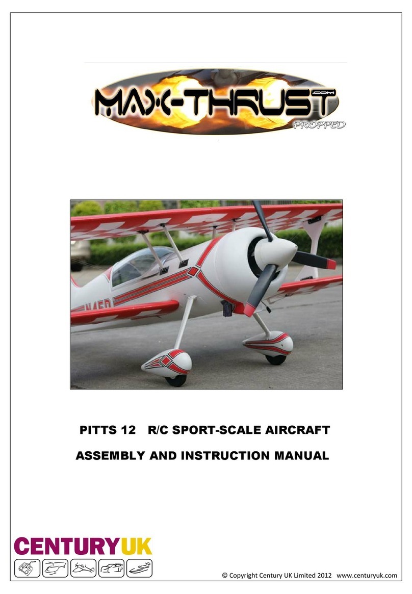
Max-Thrust PITTS 12 User guide

Max-Thrust
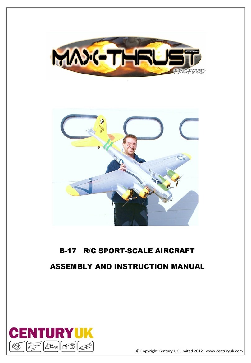
Max-Thrust B-17 User guide

Max-Thrust
Max-Thrust Mini Viper Jet User instructions

Max-Thrust
Max-Thrust Douglas A1 Skyraider User guide
Max-Thrust
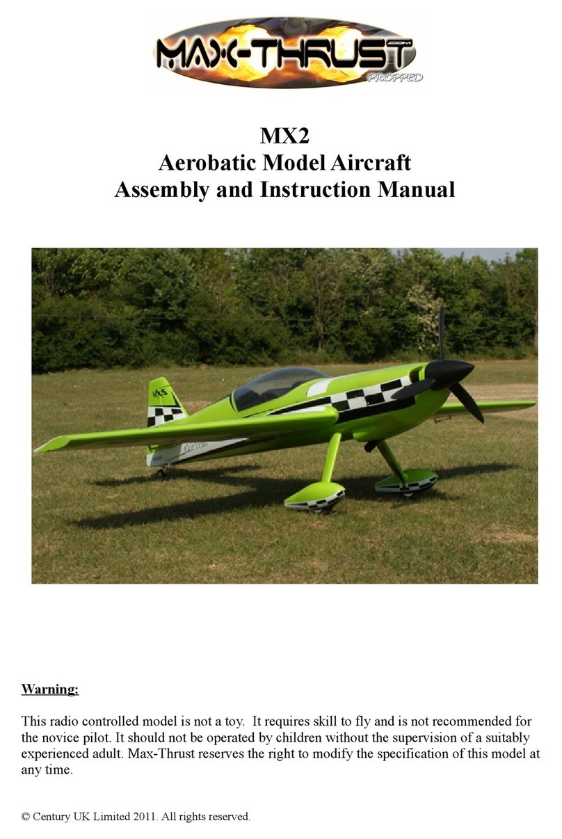
Max-Thrust MX2 User guide

Max-Thrust
Max-Thrust APPRENTICE User manual

Max-Thrust
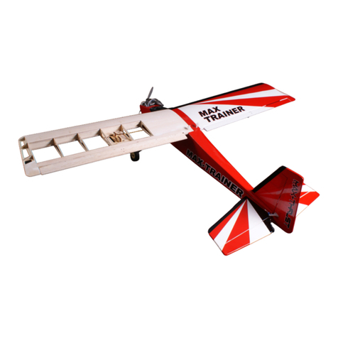
Max-Thrust MAX TRAINER Balsa Pro-Built Series User manual
Max-Thrust
Max-Thrust Ryan STA User guide