manuals.online logo
Brands
  1. Home
  2. •
  3. Brands
  4. •
  5. Maxcess
  6. •
  7. Controllers
  8. •
  9. Maxcess Magpowr IPT User manual

Maxcess Magpowr IPT User manual

IPT
Instruction Manual
www.maxcessintl.com
IPT
MI 850A126 1 D
Page 1 of 3
CURRENT TO PRESSURE TRANSDUCER OR VOLTAGE TO PRESSURE TRANSDUCER
ALL OF THE INFORMATION HEREIN IS THE EXCLUSIVE PROPRIETARY PROPERTY OF MAXCESS INTERNATIONAL, AND IS
DISCLOSED WITH THE UNDERSTANDING THAT IT WILL BE RETAINED IN CONFIDENCE AND WILL NEITHER BE DUPLICATED
NOR COPIED IN WHOLE OR IN PART NOR BE USED FOR ANY PURPOSE OTHER THAN FOR WHICH DISCLOSED.
COPYRIGHT 2004, ALL RIGHTS RESERVED.
Periodically there will be updates to this manual. The latest version is available on our website or by
calling your regional office listed on the back page of this publication.
INTRODUCTION / DESCRIPTION
The model IPT is a board level pressure controller to be mounted in a machine enclosure. The control
signal can be 4 to 20 madc or 0 to 10 vdc. The IPT incorporates an inlet valve, an exhaust valve, and a
pressure sensor all on a common manifold mounted directly to the printed circuit board. The IPT
operates by comparing the actual pressure, as measured by the pressure sensor, to the set point
reference input signal. If the actual pressure is less than the set point, the inlet valve is opened to
increase the pressure. If the actual pressure is greater than the set point, the exhaust valve is opened to
decrease the pressure.
The device can be mounted in any orientation without need for recalibration. Mounting options include:
mounting on standoffs through mounting holes provided; mounting on DIN 35 rail using mounting clips
provided; or mounting in a customer supplied DIN 35 Modular Circuit Housings.
INSTALLATION
Mount the unit in an electrical enclosure where the ambient temperature is 0 to 40ºC. The unit can be
installed in an electrical enclosure on a DIN 35 rail by installing the two mounting clips and pressing the
unit (mounting clips down) onto the rail until it snaps into place.
The IPT should be located as close as possible to the clutch or brake being controlled. Long, oversized
air lines connecting the IPT to the clutch or brake must be avoided, since they reduce system response.
Also, avoid the use of undersized fittings that will limit air flow and cause excessive pressure drop
downstream of the IPT.
The air inlet, output, and exhaust air line connections to the IPT are made through 1/8 NPT ports on the
manifold. The exhaust port can have a muffler installed, or can be plumbed out of the electrical
enclosure. The inlet port incorporates a 40-micron filter screen for large contaminates, but the air supply
to the unit must be filtered, dry and free of oil. Input pressure must be greater than the maximum required
output pressure and less than
150 psi. Input air pressure above 150 psi can damage the unit.
www.maxcessintl.com
IPT
MI 850A126 1 D
Page 2 of 3
ELECTRICAL CONNECTIONS
All electrical connections are made on terminal block TB1. Set power switch to match the voltage of the
AC line,
115 or 230vac. Connect AC power to terminals 3 and 4. Set the input jumpers JP1 and JP2 to the
positions corresponding to the control input signal type. For a 4 to 20 madc input, place the jumpers to
connect JP1-1 with JP1-2 and JP2-1 with JP2-2. For 0-10vdc input, place jumpers to connect JP1-2 with
JP1-3, and JP2-2 with JP2-3. Connect the appropriate control input signal to terminals 1 and 2. Terminal
2 is the lower potential line.
The IPT has been adjusted at the factory for a 4 to 20 madc or 0 to10 vdc control input signal to produce
a 0 to 80 psig output pressure. No further adjustments are required. However, if adjustment of the output
pressure is desired, see note below.
SPECIFICATIONS
Input Power..................................................... 115/230 vac ±10%, 50/60 Hz, switch selectable
Control Input................................................... 4 to 20 madc, 249Ωinput impedance
0 to 10 vdc, 10KΩinput impedance
Output Pressure............................................. 0 to 80 psig
Maximum Supply Pressure............................ 150 psig
Minimum Supply Pressure............................. greater than maximum desired output pressure
Linearity, Hysteresis & Repeatability............. 0.5% of full scale
30 to 10V
JP1
4 to 20mA
JUMPERS SET FOR
0 TO 10vdc CONTROL INPUT
JP23
22 11
NOTE: ADJUSTMENT (Not normally required)
The adjustment procedure is as follows:
1. Adjust the control input signal to a level slightly greater than its minimum value (0vdc or 4ma).
2. Adjust the "offset" potentiometer until the output pressure is slightly greater than zero.
3. Adjust the control input signal to its maximum value.
4. Adjust the "gain" potentiometer until the output pressure is at the desired maximum level.
5. Repeat this procedure as required.
AMERICAS
Tel +1.405.755.1600
Fax +1.405.755.8425
sales@maxcessintl.com
www.maxcessintl.com
EUROPE, MIDDLE EAST
AND AFRICA
Tel +49.6195.7002.0
Fax +49.6195.7002.933
sales@maxcess.eu
www.maxcess.eu
CHINA
Tel +86.756.881.9398
Fax +86.756.881.9393
info@maxcessintl.com.cn
www.maxcessintl.com.cn
INDIA
Tel +91.22.27602633
Fax +91.22.27602634
india@maxcessintl.com
www.maxcess.in
JAPAN
Tel +81.43.421.1622
Fax +81.43.421.2895
japan@maxcessintl.com
www.maxcess.jp
KOREA, TAIWAN,
AND SE ASIA
asia@maxcessintl.com
www.maxcess.asia
© 2018 Maxcess
2.1 [54mm]
5.25 [133mm]
5.7 [144mm]
.2 [5mm]
.2 [5mm]
4.2 [108mm]
3.83 [97.3mm]
INOUTEX (4) .204 [5.2mm]
DIA. MOUNTING
HOLES
(3) 1/8 NPT
CUSTOMER SUPPLIED
DIN 35 RAIL
.5 [12mm]
HEIGHT USING
MOUNTING FEET
1.3 [34.0mm]
GAIN
OFFSET
JP1
TERM
TB1 F2
230
L2
F1
JP2
L1-+ STRIP
0-10 VDC
4-20 mADC
CONTROL INPUT
115 OR 230 VAC

Other Maxcess Controllers manuals

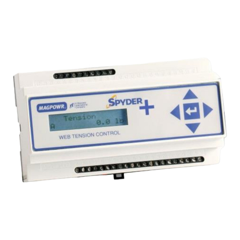
Maxcess Spyder User manual

Maxcess

Maxcess Spyder User manual

Maxcess MAGPOWR DFC-90 User manual

Maxcess

Maxcess MAGPOWR DFC-90 User manual

Maxcess Fife Polaris DP-20 User manual

Maxcess

Maxcess Fife Polaris DP-20 User manual

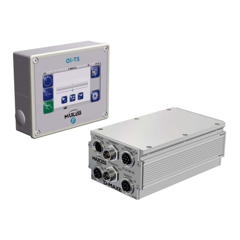
Maxcess FIFE D-MAXE 1 User manual

Maxcess

Maxcess FIFE D-MAXE 1 User manual

Maxcess H6630EM User manual

Maxcess

Maxcess H6630EM User manual

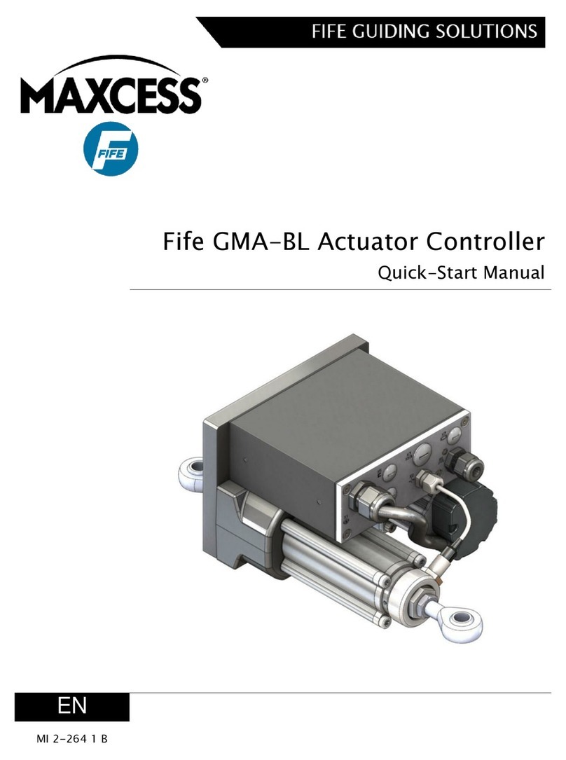
Maxcess Fife GMA-BL User manual

Maxcess

Maxcess Fife GMA-BL User manual

Maxcess Fife Polaris DP-20 User manual

Maxcess

Maxcess Fife Polaris DP-20 User manual

Maxcess D-MAXE User manual

Maxcess

Maxcess D-MAXE User manual

Maxcess GMA-BL-1-1 Manual

Maxcess

Maxcess GMA-BL-1-1 Manual

Maxcess MAGPOWR CYGNUS-S3 Series User manual

Maxcess

Maxcess MAGPOWR CYGNUS-S3 Series User manual

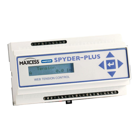
Maxcess MAGPOWR Spyder-Plus User manual

Maxcess

Maxcess MAGPOWR Spyder-Plus User manual

Maxcess SE-46C Quick start guide

Maxcess

Maxcess SE-46C Quick start guide

Maxcess Fife GMA-BL Instruction manual

Maxcess

Maxcess Fife GMA-BL Instruction manual

Maxcess FIFE DP-20 PLUS User manual

Maxcess

Maxcess FIFE DP-20 PLUS User manual

Maxcess MAGPOWR Spyder-Plus-S1 User manual

Maxcess

Maxcess MAGPOWR Spyder-Plus-S1 User manual

Maxcess MAGPOWR DLCA NET-S1 User manual

Maxcess

Maxcess MAGPOWR DLCA NET-S1 User manual

Maxcess MAGPOWR HEB250 Installation and operating instructions

Maxcess

Maxcess MAGPOWR HEB250 Installation and operating instructions

Maxcess FIFE DP-20 PLUS User manual

Maxcess

Maxcess FIFE DP-20 PLUS User manual

Popular Controllers manuals by other brands

LEGRAND Valena Allure Series user guide

LEGRAND

LEGRAND Valena Allure Series user guide

HEATIZON SYSTEMS M329 instructions

HEATIZON SYSTEMS

HEATIZON SYSTEMS M329 instructions

Emerson Fisher 3024S instruction manual

Emerson

Emerson Fisher 3024S instruction manual

Sherwood Scuba maximus SRB5600 Assembly & maintenance guide

Sherwood Scuba

Sherwood Scuba maximus SRB5600 Assembly & maintenance guide

Leviton lumina LU20S installation instructions

Leviton

Leviton lumina LU20S installation instructions

Linear Technology DC1973A Demo Manual

Linear Technology

Linear Technology DC1973A Demo Manual

Ecodhome Z-Wave installation manual

Ecodhome

Ecodhome Z-Wave installation manual

Ducati 1098R 2008 installation instructions

Ducati

Ducati 1098R 2008 installation instructions

GE IC3645SH7R353E2 Installation and operation

GE

GE IC3645SH7R353E2 Installation and operation

SOMFY animeo WM/DRM 100-240 V AC installation guide

SOMFY

SOMFY animeo WM/DRM 100-240 V AC installation guide

Computer Automation CAT-200B manual

Computer Automation

Computer Automation CAT-200B manual

Honeywell Enhanced Micro TDC 3000 user manual

Honeywell

Honeywell Enhanced Micro TDC 3000 user manual

Hunter PRO-C Hydrawise Reference card

Hunter

Hunter PRO-C Hydrawise Reference card

Magicar M4200 installation guide

Magicar

Magicar M4200 installation guide

Banner A-GAGE MINI-ARRAY MAC Series instruction manual

Banner

Banner A-GAGE MINI-ARRAY MAC Series instruction manual

Allen-Bradley Nederman 4502137 user manual

Allen-Bradley

Allen-Bradley Nederman 4502137 user manual

Evco EVJ 700 Applications manual

Evco

Evco EVJ 700 Applications manual

MADRIX ORION quick start guide

MADRIX

MADRIX ORION quick start guide

manuals.online logo
manuals.online logoBrands
  • About & Mission
  • Contact us
  • Privacy Policy
  • Terms and Conditions

Copyright 2025 Manuals.Online. All Rights Reserved.