MAXDATA Favorit 500 User manual

I
FAVORIT 500 User’s Manual
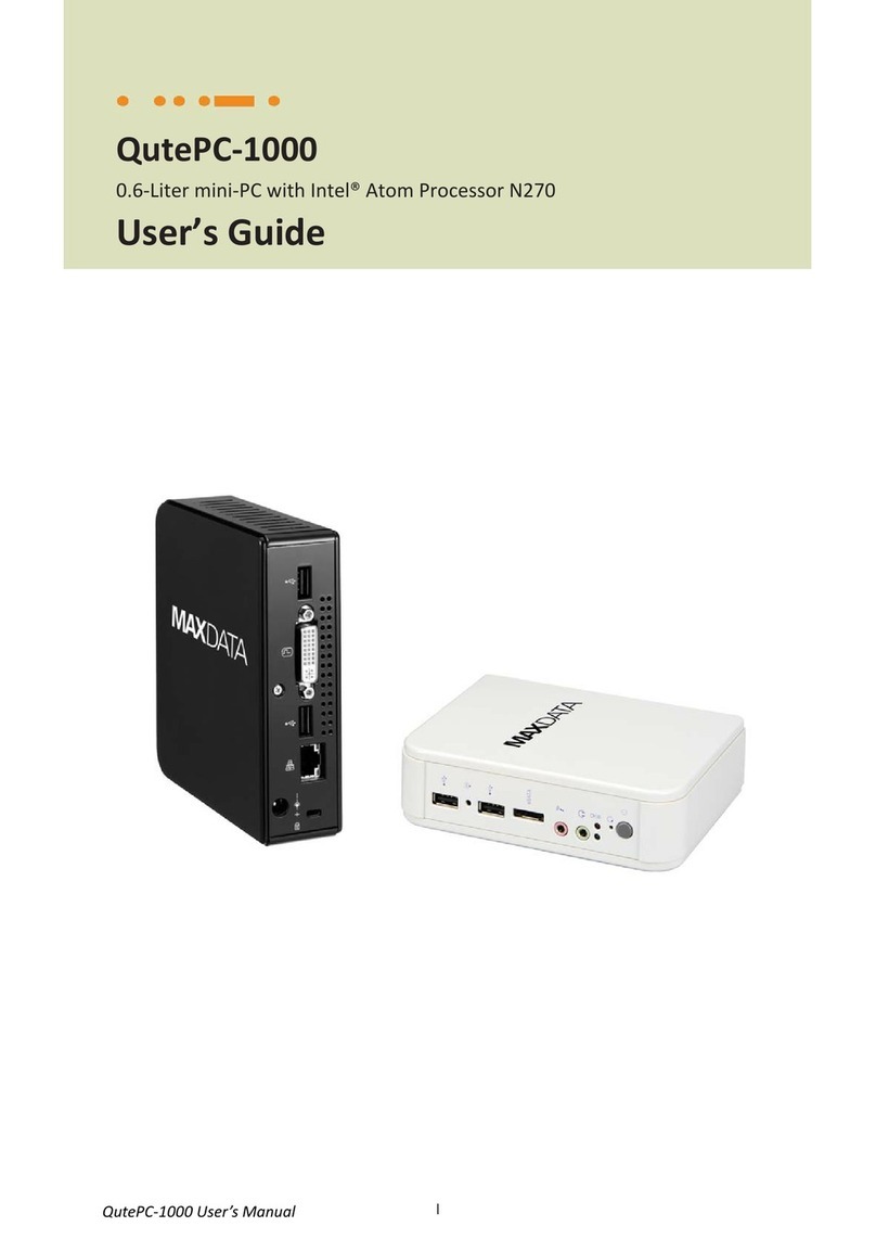
MAXDATA FAVORIT 500
Fan-less Mini-PC with Intel® Atom Processor N270
User’s Guide

II
FAVORIT 500 User’s Manual
Congratulations on your purchase of the MAXDATA personal computer! We are confident that it will meet
We have taken all possible care to ensure that this manual contains correct, accurate information. However,
we cannot assume liability for any possible errors. Please refer to your dealer for reporting errors or
comments. We appreciate all feedback and are eager to incorporate any useful suggestions and
improvements. All rights reserved. No part of this manual may be reproduced, processed or distributed in any
form (print, photocopy, microfilm or any other process) or processed by an electronic system without prior
written permission of MAXDATA. Other brand names may be registered trademarks and must be treated as
such.
© Copyright 2009 MAXDATA GmbH, Marl
reference only. MAXDATA does not assume any liability
arising out of the applicat
contain or reference information and products protected by copyrights or patents and does not convey any
license under the patent rights of MAXDATA, nor the rights of others.
MAXDATA is registered trademark of Quanmax. All trademarks, registered trademarks, and trade names used
information proprietary to MAXDATA
MAXDATA name, cover, and
logo.
MAXDATA reserves the right to make changes without notice in product or component design as warranted by
evolution in user needs or progress in engineering or manufacturing technology. Changes which affect the
MAXDATA GmbH
Elbestraße 16
45768 Marl, Germany
Phone: +49 (0) 2365 877 002
Monday–Thursday from 08:00 until 17:30
Friday from 08:00 until 16:00
www.maxdata.de
info@maxdata.de
Revision
Date
Edited by
Changes
1.0
11/05/2009
SLee
Initial Release (MAXDATA)

2
Content

Figures & Tables
3
FAVORIT 500 User’s Manual
Figures & Tables
Figure 1 FAVORIT 500 dimensions drawing ...............................................................8
Figure 2 Front Panel...................................................................................................9
Figure 3 Rear Panel ..................................................................................................11
Figure 4 Connect the DVI cable................................................................................12
Figure 5 Connecting USB mouse & keyboard ..........................................................13
Figure 6 Network cable with RJ45 connector ..........................................................13
Figure 7 Turing on the system..................................................................................14
Figure 8 VESA mounting...........................................................................................14
Figure 9 VESA Mounting Kit Dimension...................................................................15
Figure 10 Use a Kensington lock ..............................................................................15
Table 1 FAVORIT 500 product specifications..............................................................8
Table 2 BIOS Main Menu..........................................................................................17
Table 3 IDE Device Setting Menu .............................................................................17
Table 4 System Information .....................................................................................18
Table 5 Advanced Menu...........................................................................................18
Table 6 OnBoard Peripherals Configuration Settings...............................................19
Table 7 Hardware Health Configuration...................................................................20
Table 8 Boot Menu...................................................................................................20
Table 9 Chipset Menu ..............................................................................................21
Table 10 Power Menu ..............................................................................................22
Table 11 Security Menu ...........................................................................................23
Table 12 Exit Menu...................................................................................................23

Safety Instructions
4
FAVORIT 500 User’s Manual
Safety Instructions
Before You Begin
Before handling the product, read the instructions and safety guidelines on the following
pages to prevent damage to the product and to ensure your own personal safety.
Always use caution when handling/operating a computer. Only qualified,
experienced, authorized electronics service personnel should access the interior
of a computer. The power supplies produce high voltages and energy hazards,
which can cause bodily harm.
Use extreme caution when installing or removing components. Refer to the
have any questions, please contact MAXDATA Post-Sales Technical Support.
WARNING
electrical outlet. Turn off system power, turn off the power supply, and then disconnect the
power cord from its source before removing the chassis cover. Turning off the system power
switch does not remove power to components.
When Working Inside a Computer
Before taking covers off a computer, perform the following steps:
1. Turn off the computer and any peripherals.
2. Disconnect the computer and peripherals from their power sources or subsystems to
prevent electric shock or system board damage. This does not apply when hot
swapping parts.
3. on the
following page.
4. Disconnect any telephone or telecommunications lines from the computer.
In addition, take note of these safety guidelines when appropriate:
To help avoid possible damage to system boards, wait five seconds after turning off

Safety Instructions
5
FAVORIT 500 User’s Manual
the computer before removing a component, removing a system board, or
disconnecting a peripheral device from the computer.
When you disconnect a cable, pull on its connector or on its strain-relief loop, not on
the cable itself. Some cables have a connector with locking tabs. If you are
disconnecting this type of cable, press in on the locking tabs before disconnecting the
cable. As you pull connectors apart, keep them evenly aligned to avoid bending any
connector pins. Also, before connecting a cable, make sure both connectors are
correctly oriented and aligned.
CAUTION
installation and troubleshooting instructions closely.
Preventing Electrostatic Discharge
Static electricity can harm system boards. Perform service at an ESD workstation and follow
proper ESD procedure to reduce the risk of damage to components. MAXDATA strongly
encourages you to follow proper ESD procedure, which can include wrist straps and smocks,
when servicing equipment.
You can also take the following steps to prevent damage from electrostatic discharge (ESD):
When unpacking a static-sensitive component from its shipping carton, do not remove
are ready to install the
component in a computer. Just before unwrapping the antistatic packaging, be sure
you are at an ESD workstation or grounded. This will discharge any static electricity
that may have built up in your body.
When transporting a sensitive component, first place it in an antistatic container or
packaging.
Handle all sensitive components at an ESD workstation. If possible, use antistatic floor
pads and workbench pads.
contacts
on a board. Hold a board by its edges or by its metal mounting bracket.
Do not handle or store system boards near strong electrostatic, electromagnetic,
magnetic, or radioactive fields.
Instructions for Lithium Battery

Safety Instructions
6
FAVORIT 500 User’s Manual
WARNING
Danger of explosion when battery is replaced with incorrect type. Only replace with
the same or equivalent type recommended by the manufacturer.
Do not dispose of lithium batteries in domestic waste. Dispose of the battery according to
the local regulations dealing with the disposal of these special materials (e.g. to the
collecting points for disposal of batteries)
Voltage Ratings
The external power adaptor of the FAVORIT 500 has the following voltage ratings:
Input: 100-240 VAC, 50-60 Hz
Output: 30W, 12VDC , 2.5A
Power Supplies:
Touch Electronic Co Ltd / SA06-30S12R-W
Lite-On Technology Corp / PA-1300-014XX ( X can be A-Z, 0-9,”-“ or blank)

Chapter 1
7
FAVORIT 500 User’s Manual
Chapter 1
Introduction
Overview
The FAVORIT 500 is a mini PC is ideal for space critical applications. This system is designed
with Intel® Atom N270 Processor which provides with excellent performance enabled by
next- generation 45nm Process Technology. The system is supported with Intel® 945GSE /
ICH7-M chipset, and DDR2 SO-
eSATA, Audio out, MIC in, GbE, USB 2.0 and DVI-I.
Checklist
FAVORIT 500
Power Adapter
Power Cord
Driver CD
Quick installation Guide
Optional VESA Mounting Kit
Optional wireless LAN antennas
Features
Ultra Quiet, Ultra Small, Ultra-Low Power
Intel® Atom Processor N270
Intel® 945GSE + ICH7-M
Support DDR2 533 SODIMM up to 2GB
Support 1x DVI-

Chapter 1
8
FAVORIT 500 User’s Manual
Product Specifications
Dimensions
170 x 47x 110 mm (WxHxD)
Weight
1.2 kg
CPU/ Chipset
Intel® Atom N270 Processor , 945GSE / ICH7-M
RAM
1 x DDR2 533 SO-DIMM up to 2GB
Storage
Front IO
1x Line-Out, 1x MIC-In
1x Push button for power on/off
1x Push button for reset
1x POWER LED
1x HDD LED
1x Wifi LED
2x USB2.0
1x eSATA connector
Rear IO
1x DC JACK
1x DVI-I connector for CRT or DVI output
2x USB2.0
1x RJ-45, GbE port
Wireless LAN
Optional Mini PCIe WI-FI Card
Cooling
Fanless
Power Unit
Input: 100-240 VAC, 50-60 Hz
Output: 30W, +12Vdc, 2.5A
Mounting
Desktop, VESA-mount
Certifications
CE, FCC Class B
Table 1 FAVORIT 500 product specifications
Figure 1 FAVORIT 500 dimensions drawing

Chapter 1
9
FAVORIT 500 User’s Manual
System tour
Refer to the diagrams below to identify the components of the system.
Front Panel
Figure 2 Front Panel
USB
The USB (Universal Serial Bus) port is compatible with USB devices such as keyboards,
mouse devices, cameras, and hard disk drives. USB allows many devices to run
simultaneously on a single computer, with some peripheral acting as additional
plug-in sites or hubs.
WiFi LED
When the data is transferring, the WiFi LED will blink.
eSATA
The eSATA connector provides an external connectivity for mass storage devices.
CAUTION
This connector do not support hot-swapping. Users should not connect or
disconnect their eSATA devices from PC when the system is working.
MIC-IN
The microphone jack is designed to connect the microphone used for video
conferencing, voice narrations, or simple audio recordings.

Chapter 1
10
FAVORIT 500 User’s Manual
Headphone Jack
to amplified speakers or headphones.
Power LED
The power LED will light when the PC is power-on.
HDD LED
The hard disk LED blinks when data is being written into or read from the HDD.
Reset Button
To reset the computer, use the tip of a pen to press the Reset button briefly (for less
than three seconds).
Power Switch
The power switch allows powering ON and OFF the system.

Chapter 1
11
FAVORIT 500 User’s Manual
Rear Panel
Figure 3 Rear Panel
USB
The USB (Universal Serial Bus) port is compatible with USB devices such as keyboards,
mouse devices, cameras, and hard disk drives. USB allows many devices to run
simultaneously on a single computer, with some peripheral acting as additional
plug-in sites or hubs.
DVI Port
The Digital Visual Interface (DVI-I) port supports a high quality VGA-compatible device
such as a monitor or LCD TV to allow viewing on a larger external display.
Ethernet
The eight-pin RJ-45 LAN port supports a standard Ethernet cable for connection to a
local network.
DC Jack
The supplied power adapter converts AC power to DC for use with this jack. Power
supplied through this jack supplies power to the PC. To prevent damage to the PC,
always use the supplied power adapter.
Kensington Lock Slot
The slot is used for attaching a lock-and-cable apparatus. Locks are generally secured
in place with a key or combination lock attached to a rubberized metal cable.
WLAN-Antenne
WLAN-Antenne

Chapter 2
12
FAVORIT 500 User’s Manual
Chapter 2
Getting Started
Setting up your PC
Connecting the monitor
Connect the DVI cable from your display to the DVI port.
Figure 4 Connect the DVI cable
NOTE
To connect a VGA display, you need the DVI to VGA adapter to connect a display
with a VGA connector.
NOTE
When the system reboots without connecting the DVI, there might be no image
on screen when you insert the DVI cable. Please pressing <Ctrl>+<Alt>+<F4>
simultaneously to show the image on screen.

Chapter 2
13
FAVORIT 500 User’s Manual
Connecting USB mouse & keyboard
Your FAVORIT 500 does not come with a keyboard and mouse, but you can use any USB
keyboard or mouse with your computer.
Figure 5 Connecting USB mouse & keyboard
NOTE
Using a third-party USB mouse or keyboard may require software drivers. Check the
manufacturers website for the latest software drivers.
Connecting to a network device
Connect one end of a network cable to the LAN port on the system rear panel and the
other end to a hub or switch.
Figure 6 Network cable with RJ45 connector

Chapter 2
14
FAVORIT 500 User’s Manual
Turning on the system
1. Connect the power adapter cable to the DC jack (DC IN) of the FAVORIT 500
2. Connect the power cable to the power adapter
3. Connect the power cable to a power outlet
4. Press the power switch on the front panel to turn on the system
Figure 7 Turing on the system
Mounting your PC to a monitor
1. Secure the VESA mounting kit to your monitor with four screws.
NOTE
To fasten the metal shelf, your monitor must comply with VESA75 or VESA100
standard. The VESA mounting kit is optional.
2. Place the FAVORIT 500 on the VESA mounting bracket and make sure the bracket
is hooked with the fins of the system housing.
3. Secure the screw with the VESA mounting bracket and make sure the FAVORIT
500 is solidly secured to the display.
Figure 8 VESA mounting

Chapter 2
15
FAVORIT 500 User’s Manual
NOTE
When mounting the unit on the wall with a display. The total weight of the unit
Figure 9 VESA Mounting Kit Dimension
Anti-theft protection with a Kensington Lock
The FAVORIT 500 has a Kensington lock slot for the Kensington MicroSaver. With the
Kensington MicroSaver, a sturdy steel cable, you can attach your FAVORIT 500 to a
stationary object and protect your PC from theft.
Figure 10 Use a Kensington lock

Chapter 3
16
FAVORIT 500 User’s Manual
Chapter 3
AMI BIOS Setup
Overview
This chapter provides a description of the AMI BIOS. The BIOS setup menus and available
selections may vary from those of your product. For specific information on the BIOS for
your product, please contact MAXDATA.
NOTE: The BIOS menus and selections for your product may vary from those in
this chapter. For the BIOS manual specific to your product, please contact
MAXDATA.
AMI's ROM BIOS provides a built-in Setup program, which allows the user to modify the
basic system configuration and hardware parameters. The modified data will be stored in a
battery-backed CMOS, so that data will be retained even when the power is turned off. In
general, the information saved in the CMOS RAM will not need to be changed unless there
is a configuration change in the system, such as a hard drive replacement or when a device
is added.
It is possible for the CMOS battery to fail, which will cause data loss in the CMOS only. If
this happens you will need to reconfigure your BIOS settings.

Chapter 3
17
FAVORIT 500 User’s Manual
Main Menu
The BIOS Setup is accessed by pressing the DEL key after the Power-On Self-Test (POST)
memory test begins and before the operating system boot begins. Once you enter the BIOS
Setup Utility, the Main Menu will appear on the screen. The Main Menu provides System
cursor keys to navigate between menu screens.
Table 2 BIOS Main Menu
BIOS SETUP UTILITY
Main Advanced Boot Chipset Power Security Exit
System Date [Mon 04/03/2009]
System Time [10:18:15]
> Primary IDE Master :[Not Detected]
> Primary IDE Slave :[Not Detected]
> Secondary IDE Master :[Not Detected]
> System Information
Use [ENTER], [TAB]
or [SHIFT-TAB] to
select a field.
Use [+] or [-] to
configure system Time.
<> Select Screen
+- Change Field
Tab Select Field
F1 General Help
F10 Save and Exit
ESC Exit
V02.61 (C)Copyright 1985-2006, American Megatrends, Inc.
Below table is described for Primary IDE Master, Primary IDE Slave, Secondary IDE Master
setting.
Table 3 IDE Device Setting Menu
BIOS SETUP UTILITY
Main Advanced Boot Chipset Power Security Exit
Primary Master
Device :Not Detected
LBA/ Large Mode [Auto]
DMA Mode [Auto]
S.M.A.R.T [Auto]
Disable: Disables LBA Mode.
Auto: Enables LBA Mode if the
device supports it and the device
is not already formatted with LBA
Mode disabled.
<> Select Screen
+- Change Field
Tab Select Field
F1 General Help
F10 Save and Exit
ESC Exit
V02.61 (C)Copyright 1985-2006, American Megatrends, Inc.
LBA/ Large Mode [Auto]
Enables or disables the LBA (Logical Block Addressing)/ Large mode. Setting to Auto
enables the LBA mode if the device supports this mode, and if the device was not

Chapter 3
18
FAVORIT 500 User’s Manual
previously formatted with LBA mode disabled.
Options: Disabled, Auto
DMA Mode [Auto]
Options: Auto
S.M.A.R.T [Auto]
SMART stands for Smart Monitoring, Analysis, and Reporting Technology. It allows AMIBIOS
to use the SMART protocol to report PC system information over a network.
Options: Auto, Disabled, Enabled
Table 4 System Information
BIOS SETUP UTILITY
Main Advanced Boot Chipset Power Security Exit
BIOS
Version : 1.3
Build Date: :04/03/0 9
Processor
Intel® CPU N270 @ 1.60GHz
Speed :1600MHz
Count :1
System Memory
Size :1016MB
<> Select Screen
+- Change Field
Tab Select Field
F1 General Help
F10 Save and Exit
ESC Exit
V02.61 (C)Copyright 1985-2006, American Megatrends, Inc.
Advanced Menu
Table 5 Advanced Menu
BIOS SETUP UTILITY
Main Advanced Boot Chipset Power Security Exit
Advanced Settings
Warning: Setting wrong values in below sections
may cause system to malfunction.
> OnBoard Peripherals Configuration
> Hardware Health Configuration
<> Select Screen
+- Change Field
Tab Select Field
F1 General Help
F10 Save and Exit
ESC Exit
V02.61 (C)Copyright 1985-2006, American Megatrends, Inc.
Press <Enter> to select a sub-menu for detailed options.

Chapter 3
19
FAVORIT 500 User’s Manual
Table 6 OnBoard Peripherals Configuration Settings
BIOS SETUP UTILITY
Main Advanced Boot Chipset Power Security Exit
OnBoard Peripherals Configuration Settings
USB Controller [Enabled]
USB 2.0 Controller [Enabled]
USB Device Legacy Support [Enabled]
Audio Controller [Enabled]
Onboard LAN Controller [Enabled]
Onboard LAN OPTROM [Disabled]
WLAN Controller [Enabled]
Options
Disabled
Enabled
<> Select Screen
+- Change Field
Tab Select Field
F1 General Help
F10 Save and Exit
ESC Exit
V02.61 (C)Copyright 1985-2006, American Megatrends, Inc.
USB Controller [Enabled]
Options: Enabled, Disabled
USB 2.0 Controller [Enabled]
Options: Enabled, Disabled
USB Device Legacy Support [Enabled]
Options: Enabled, Disabled, Auto
Audio Controller [Enabled]
Options: Enabled, Disabled
Onboard LAN Controller [Enabled]
Options: Enabled, Disabled
Onboard LAN OPTROM [Disabled]
Options: Enabled, Disabled
WLAN Controller [Enabled]
Options: Enabled, Disabled
Other manuals for Favorit 500
1
Table of contents
Other MAXDATA Desktop manuals

MAXDATA
MAXDATA FUSION 6000 I User guide

MAXDATA
MAXDATA Ultra Small Desktop User manual

MAXDATA
MAXDATA Ultra Small Desktop User manual

MAXDATA
MAXDATA Workstation Fusion 7000 User manual

MAXDATA
MAXDATA FAVORIT XS Series User manual

MAXDATA
MAXDATA PCATXUK1.1 User manual

MAXDATA
MAXDATA Favorit 500 User manual

MAXDATA
MAXDATA QutePC?1000 User manual
Popular Desktop manuals by other brands

IBM
IBM NetVista X40 Uživatelská příručka

Radio Shack
Radio Shack TRS-80 owner's manual

Lenovo
Lenovo Erazer X700 Hardware Maintenance Manual

Sony
Sony PCV-R545DS VAIO Computer User Guide (primary... owner's guide

Dell
Dell Dimension 0JG507A01 Quick setup guide

Lenovo
Lenovo ThinkCentre M70z Handboek voor de gebruiker