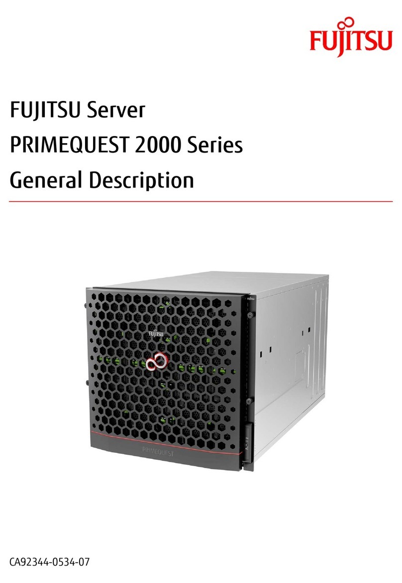
4 PBMAXDATA Server PLATINUM 500 I M7Contents
Figures
1. Back Panel Connectors .....................................................................................................................6
2. Front controls and indicators.............................................................................................................7
3. Server Board Connector and Component Locations ......................................................................10
4. Configuration Jumpers....................................................................................................................11
5. Diagnostic LEDs for Light Guided Diagnostics................................................................................11
6. SSI Front Panel Connector ..............................................................................................................12
7. DIMM Configuration........................................................................................................................13
8. Bezel assembly ...............................................................................................................................15
9. Releasing Drive Carrier from Hot Swap Cage .................................................................................16
10. Removing Plastic Retention Device ................................................................................................17
11. Securing Hard Drive to Drive Cage..................................................................................................17
12. Inserting Drive Carrier into Drive Cage............................................................................................17
13. Installing Memory............................................................................................................................18
14. Opening the Processor Socket Lever..............................................................................................20
15. Opening Load Plate.........................................................................................................................20
16. Removing Protective Covering from the Load Plate .......................................................................20
17. Inserting the Processor ...................................................................................................................20
18. Close and Lock Load Plate ..............................................................................................................21
19. Installing the Heat Sink....................................................................................................................21
20. Replacing the Battery......................................................................................................................24
Tables
1. NIC LEDs...........................................................................................................................................6
2. Server System Features....................................................................................................................9
3. LEDs................................................................................................................................................12
4. Keyboard Commands......................................................................................................................26
5. Efficiency of the 600 W power supply (FSP600-80PSA) .................................................................31
6. 600 W Power Supply Output Rating ...............................................................................................31
7. 650 W Power Supply Output Rating ...............................................................................................31
8. Environmental Specifications ..........................................................................................................32
9. Product Certification Markings ........................................................................................................33
6 Technical Reference 31
Power Supply Specifications .................................................................................................................31
600 W Single Power Supply Input Voltages.....................................................................................31
Efficiency..........................................................................................................................................31
600 W Single Power Supply Output Voltages..................................................................................31
650 W Redundant Power Supply Input Voltages .............................................................................31
650 W Redundant Power Supply Output Voltages ..........................................................................31
System Environmental Specifications ...................................................................................................32
7 Regulatory and Integration Information 33
Product Regulatory Compliance ............................................................................................................33
Product Safety Compliance ..............................................................................................................33
Product EMC Compliance ...............................................................................................................33
Product Regulatory Compliance Markings .......................................................................................33
Product RoHS Compliance ...............................................................................................................33
Installation Precautions .........................................................................................................................33
Installation Requirements......................................................................................................................34
Prevent Power Supply Overload ......................................................................................................34
Place Battery Marking ......................................................................................................................34
Use Only for Intended Applications.......................................................................................................34
Power and Electrical Warnings..............................................................................................................34
Rack Mount Warnings...........................................................................................................................35
