manuals.online logo
Brands
  1. Home
  2. •
  3. Brands
  4. •
  5. MAXDATA
  6. •
  7. Server
  8. •
  9. MAXDATA PLATINUM 1600 IR User manual

MAXDATA PLATINUM 1600 IR User manual

MAXDATA PLATINUM 1600 IR – Quick Start Guide
Safety
Thank you for buying a MAXDATA PLATINUM
1600 IR Server. This document describes how
to set up the system, turn on the system and
complete configuration for the system.
Installation and service
Installation and service of this product is to be performed only by qualified service
personnel to avoid risk of injury from electrical shock or energy hazard.
Enclosure cover
In order to comply with applicable safety, emission and thermal requirements, no
covers should be removed and all bays must be fitted with drive carriers.
Battery safety
There is a danger of explosion if the battery is incorrectly replaced.
Dispose of used batteries in accordance with the manufacturer’s instructions and
national regulations.
Warning
Caution
Electrostatic discharge
Observe normal electrostatic discharge (ESD) procedures during system integration
to avoid possible damage to the server board and/or other components of the server
system.
Server system power
System power on/off: The power button DOES NOT turn off the system AC power. To
remove power from server system, you must unplug the AC power cord from the wall
outlet or the chassis.
Site Selection
Technical Specification
Dimensions:
- 43.2 mm high
- 438 mm wide
- 704.8 mm deep
- 21 kg max. weight
System power:
- 100–127 V at 50/60 Hz, 9.2 A max.
- 200–240 V at 50/60 Hz, 4.4 A max.
Temperature range: +10 °C to +30 °C
Regulatory Compliance
This product complies to the following requirements:
- EN 60950 – Safety
- EN 55022 – Emissions
- EN 55024 – Immunity
- EN 61000-3-2 – Harmonics
- EN 61000-3-3 – Voltage Flicker
- CE – EMC Directive 89/336/EWG
This product has a CE declaration of conformity (CENELEC Europe).
This server system is compliant to European Directive 2002/95/EC (RoHS).
The system is designed to operate in a typical office environment. Choose a site that is:
• Clean,dryandfreeofairborneparticles(otherthannormalroomdust).
• Well-ventilatedandawayfromsourcesofheatincludingdirectsunlightandradiators.
• Awayfromsourcesofvibrationorphysicalshock.
• Isolatedfromstrongelectromagneticeldsproducedbyelectricaldevices.
• Inregionsthataresusceptibletoelectricalstorms,werecommendyouplugyoursystemintoa
surge suppressor and disconnect telecommunication lines to your modem during an electrical
storm.
• Providedwithaproperlygroundedwalloutlet.
• Provided with sufcient space to access the power supply cord(s) because they serve as the
product’s main power disconnect.
System Overview
Follow the link “User-Support und Treiber” on www.maxdata.de to access the download area and
download a more detailed guide.
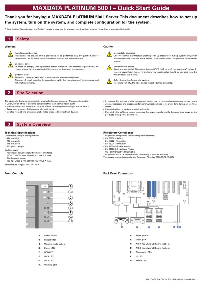
Chassis Components
Control Panel
Rear of Server System
MAXDATA PLATINUM 1600 IR M3 – Quick Start Guide 1
A. ID button with ID LED F. Status LED
B. NMI button (recessed,
tool required for use)
G. Powerbuttonwith
power LED
C. NIC 1 activity LED H. Hard drive activity LED
D. NIC 3 activity LED I. NIC 4 activity LED
E. Reset button J. NIC 2 activity LED
A
C
D
E
F
G
H
I
J
K
B
A. Hot-swap hard drive bays G. Server board
B. Front control panel H. CPU2
C. Powersupplymodule1 I. CPU1
D. Powersupplymodule2 J. System fans
E. Riser card assembly 2 K. Air duct
F. Riser card assembly 1
A. Powersupplymodule1 G. Video port
B. Powersupplymodule2 H. Serial port A (RJ-45)
C. NIC 1 I. USB ports
D. NIC 2 J. RMM 4 NIC port (optional)
E. NIC 3 K. I/O module (optional)
F. NIC 4 L. Add-in adapter slots via
riser cards 1 and 2
Server Board Connector and Component Locations
A. ID LED T. Hot-swap backplane power connector AM. Optional riser 1 power connector
B. Status LED U. CPU2DIMMslots–memorybanksEandF AN. SATA only port 1
C. Diagnostic LEDs V. System fan 5 connector AO. SATA only port 0
D. 3 USB ports W. System fan 6 connector A P.
Optional SAS module connector
E. Serial port A (RJ-45) X. Front panel USB connector AQ. 3-pin hot-swap backplane SMBUS connector
F. Video port Y. Front panel video connector AR. BMC firmware force update jumper block
G. NIC 4 Z. 30-pin (SSI compatible) front panel header AS. 2-pin hard drive activity LED header
H. NIC 3 AA. Chassis intrusion switch header AT. 4-pinIPMBconnector
I. NIC 2 AB. CPU2socket AU.
4-port SATA/SAS connector (drives 4–7)
J. NIC 1 AC. CPU2DIMMslots–memorybanksGandH AV. Serial port B (DH-10)
K. eUSB SSD connector (optional) AD. System fan 4 connector AW. OptionalTPMconnector
L. Riser card slot 2 AE. System fan 3 connector AX. Riser card slot 1
M. Board update/recovery jumper block A F. Optional ODD/SSD power connector AY.
4-port SATA/SAS connector (drives 0–3)
N. CMOS battery AG. CPU1DIMMslots–memorybanksAandB AZ. Optional I/O module connector
O. Optional riser 2 power connector AH. CPU1socket BA. USB 2.0 port
P. Main power slot 2 AI. CPU1DIMMslots–memorybanksCandD BB. Optional RMM 4 NIC
Q. CPU2fanconnector AJ. System fan 2 connector BC. Optional RMM 4 LITE
R. CPUpower-inand-outconnectors(factory
cable installed between these connectors)
AK. System fan 1 connector BD. Optional Intel®C600 RAID upgrade key
connector
S. Main power slot 1 AL. CPU1fanconnector BE. Serial A jumper
2MAXDATA PLATINUM 1600 IR M3 – Quick Start Guide
Installing the Air Duct
Removing the Air Duct
Installing the Front Bezel
Removing the Front Bezel
Removing the Server System Cover
Remove the shipping screws (A).
While pressing the blue buttons at the top of the chassis (B), slide the top cover back
until it stops (C).
Unlock the bezel if it is locked.
Lock the right end of the front bezel to the rack handle (A).
Remove the left end of front bezel from the rack handle (A).
Carefully push down the air duct into place, making sure that the cables run through
the provided openings.
Rotate the front bezel clockwise till the left end clicks into place (B).
Remove the air duct by lifting it straight up.
Align the two holes on the air duct with the alignment pins on the chassis.
Rotate the front bezel anticlockwise to release the latches on the right end from the rack
handle (B).
Lock the bezel if needed.
MAXDATA PLATINUM 1600 IR M3 – Quick Start Guide 3
Grasp the riser assembly with both hands and pull it up to remove it from the system.
Positiontherisercardedgeconnectorovertheserverboardrisersocketandalignthe
two hooks on the back edge of the riser assembly with the slots on the back of the
chassis, then press it straight down into the riser socket.
Removing the PCI Card RiserAssembly
Installing the PCI Card Riser Assembly
Riser card connector
Hooks
Slots
Remove the plastic air baffle.
Pressthegreenlatchattherearofthe powersupplyandpullthe powersupplyfrom
the chassis.
Install the hard disk drive.
Insert the replacement power supply module into the power supply cage until it clicks
into place.
Install the carrier assembly.
Hard drives are numbered from bottom to top and from left to right in ascending order.
Installing Hard Drives
Replacing the Hotswap Power Supply
Caution
Any empty drive bays must be occupied by carriers with baffles to maintain proper system
cooling.
To avoid possible damage to your chassis, use only carriers that came with your server system.
Note
The carrier lever must be held in the FULLY OPEN position to install it into the chassis. Slide the
carrier into the chassis until it stops, then rotate the lever until it snaps shut.
Hard Drive Numbering
4MAXDATA PLATINUM 1600 IR M3 – Quick Start Guide
Baffle
Drive Carrier
Attach with
four screws
RemovethePCIriserassembly.
Remove the filler panel from the add-in card slot and remove the screw (A).
Insert the add-in card until it seats in the riser connector (B).
Secure the add-in card with the screw you removed in step 2 (C).
InstallthePCIriserassemblyintotheserversystem.
Installing a PCI Addin Card

Other manuals for PLATINUM 1600 IR

1

Other MAXDATA Server manuals

MAXDATA PLATINUM 1500 IR M5 User manual

MAXDATA

MAXDATA PLATINUM 1500 IR M5 User manual

MAXDATA PLATINUM 7200 IR User manual

MAXDATA

MAXDATA PLATINUM 7200 IR User manual

MAXDATA PLATINUM 3200 I M5 User manual

MAXDATA

MAXDATA PLATINUM 3200 I M5 User manual

MAXDATA PLATINUM 3200 I M5 User manual

MAXDATA

MAXDATA PLATINUM 3200 I M5 User manual

MAXDATA PLATINUM 2200 IR User manual

MAXDATA

MAXDATA PLATINUM 2200 IR User manual

MAXDATA PLATINUM 300 IR User manual

MAXDATA

MAXDATA PLATINUM 300 IR User manual

MAXDATA PLATINUM 1600 IR User manual

MAXDATA

MAXDATA PLATINUM 1600 IR User manual

MAXDATA PLATINUM 5220 User manual

MAXDATA

MAXDATA PLATINUM 5220 User manual

MAXDATA PLATINUM 400IR M6 User manual

MAXDATA

MAXDATA PLATINUM 400IR M6 User manual

MAXDATA PLATINUM 500 I User guide

MAXDATA

MAXDATA PLATINUM 500 I User guide

MAXDATA PLATINUM 3200 I M5 User manual

MAXDATA

MAXDATA PLATINUM 3200 I M5 User manual

MAXDATA PLATINUM 100 I User guide

MAXDATA

MAXDATA PLATINUM 100 I User guide

MAXDATA PLATINUM 2200 IR User manual

MAXDATA

MAXDATA PLATINUM 2200 IR User manual

MAXDATA PLATINUM 400 IR User manual

MAXDATA

MAXDATA PLATINUM 400 IR User manual

MAXDATA PLATINUM 200 I User manual

MAXDATA

MAXDATA PLATINUM 200 I User manual

MAXDATA PLATINUM 9000-4R User manual

MAXDATA

MAXDATA PLATINUM 9000-4R User manual

MAXDATA PLATINUM 200 I User manual

MAXDATA

MAXDATA PLATINUM 200 I User manual

MAXDATA PLATINUM 2200 IR User manual

MAXDATA

MAXDATA PLATINUM 2200 IR User manual

MAXDATA PLATINUM 7200 IR User manual

MAXDATA

MAXDATA PLATINUM 7200 IR User manual

MAXDATA PLATINUM 500 I User guide

MAXDATA

MAXDATA PLATINUM 500 I User guide

MAXDATA PLATINUM 2200 IR User manual

MAXDATA

MAXDATA PLATINUM 2200 IR User manual

MAXDATA PLATINUM 7200 IR User manual

MAXDATA

MAXDATA PLATINUM 7200 IR User manual

MAXDATA PLATINIUM 9000-4R User manual

MAXDATA

MAXDATA PLATINIUM 9000-4R User manual

MAXDATA PLATINUM 100 I User manual

MAXDATA

MAXDATA PLATINUM 100 I User manual

Popular Server manuals by other brands

HP Sa3110 - VPN Server Appliance reference guide

HP

HP Sa3110 - VPN Server Appliance reference guide

Cisco UCS B420 M3 Installation and service note

Cisco

Cisco UCS B420 M3 Installation and service note

Cisco UCS B200 datasheet

Cisco

Cisco UCS B200 datasheet

Compaq 108164-003 - ProLiant - 800 Technical guide

Compaq

Compaq 108164-003 - ProLiant - 800 Technical guide

QUANTA W Mainboard Series S210-MBT2W Technical guide

QUANTA

QUANTA W Mainboard Series S210-MBT2W Technical guide

Dell PowerEdge T710 Information update

Dell

Dell PowerEdge T710 Information update

Dell PowerEdge T710 Information update

Dell

Dell PowerEdge T710 Information update

HP D7171A - NetServer - LPr Installation

HP

HP D7171A - NetServer - LPr Installation

HP Integrity BL860c release note

HP

HP Integrity BL860c release note

HPE ProLiant DL325 Gen10 user guide

HPE

HPE ProLiant DL325 Gen10 user guide

EMC Avamar Data Store Gen4T Customer service guide

EMC

EMC Avamar Data Store Gen4T Customer service guide

IBM SAN Volume Controller 2145 quick start guide

IBM

IBM SAN Volume Controller 2145 quick start guide

Dell PowerEdge 8450 Information update

Dell

Dell PowerEdge 8450 Information update

Dell PowerEdge C6145 Getting started guide

Dell

Dell PowerEdge C6145 Getting started guide

HP ProLiant ML110 Operating system installation guide

HP

HP ProLiant ML110 Operating system installation guide

Merging Ovation user manual

Merging

Merging Ovation user manual

QAT RS3 manual

QAT

QAT RS3 manual

Lenovo 70AR User guide and hardware maintenance manual

Lenovo

Lenovo 70AR User guide and hardware maintenance manual

manuals.online logo
manuals.online logoBrands
  • About & Mission
  • Contact us
  • Privacy Policy
  • Terms and Conditions

Copyright 2025 Manuals.Online. All Rights Reserved.