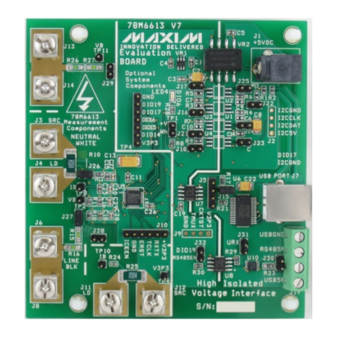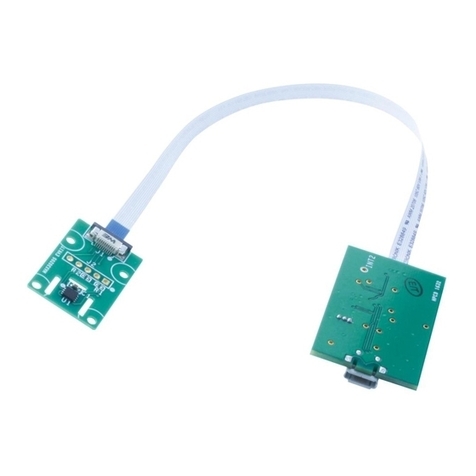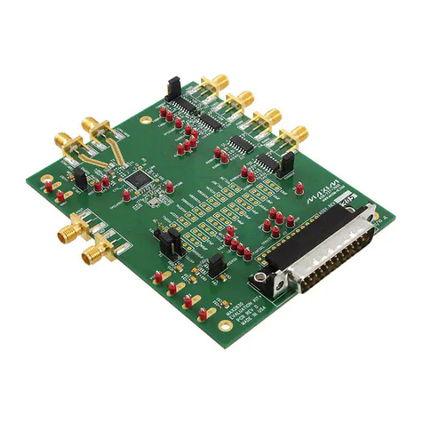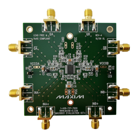
78M6610+LMU Evaluation Kit User Manual
2 Rev 1
Table of Contents
1Introduction .........................................................................................................................................4
1.1 Ordering Information..................................................................................................................4
1.2 Package Contents......................................................................................................................4
1.3 System Requirements ...............................................................................................................4
1.4 Safety and ESD Notes...............................................................................................................5
1.5 Testing the 78M6610+LMU EV Board Prior to Shipping...........................................................5
2USB Driver Installation .......................................................................................................................6
2.1.1 Confirm COM Port Mapping.............................................................................................6
2.1.2 FTDI COM Port Trouble Shooting....................................................................................6
3Hardware Setup: Sensor Interface ....................................................................................................7
3.1 Single-Phase Measurements using Shunts...............................................................................7
3.1.1 Jumper and Switch Descriptions......................................................................................8
3.1.2 Device Configuration........................................................................................................8
3.2 Single/Multiphase Measurements Using CTs............................................................................9
3.2.1 Jumper Position Changes..............................................................................................10
3.2.2 Device Configuration......................................................................................................10
3.3 Pseudo-Isolated Single-Phase Measurements Using CTs......................................................21
3.3.1 Jumper Position Changes..............................................................................................23
3.3.2 Device Configuration......................................................................................................23
4Hardware Setup: Digital Interface....................................................................................................11
4.1 USB Interface...........................................................................................................................11
4.2 RS-485 Interface......................................................................................................................12
5Graphical User Interface (GUI).........................................................................................................13
5.1 GUI Initialization.......................................................................................................................13
5.1.1 SSI Tab..........................................................................................................................13
5.1.2 Device Tab.....................................................................................................................14
5.1.3 Direct Tab.......................................................................................................................14
5.1.4 Configuration Tab...........................................................................................................15
5.1.5 Command Register Tab.................................................................................................15
5.1.6 Calibration Tab...............................................................................................................16
5.1.7 Power Tab......................................................................................................................16
5.1.8 Energy Tab.....................................................................................................................17
5.1.9 Fundamental Tab...........................................................................................................17
5.1.10 Min/Max Tab.................................................................................................................17
5.1.11 Alarms Tab ...................................................................................................................18
5.1.12 Monitor Tab,..................................................................................................................19
6Hardware Design Information..........................................................................................................24
6.1 Board Schematics....................................................................................................................24
6.2 Bill of Materials.........................................................................................................................28
6.3 PCB Layout..............................................................................................................................30
7Contact Information..........................................................................................................................32
Revision History........................................................................................................................................32
