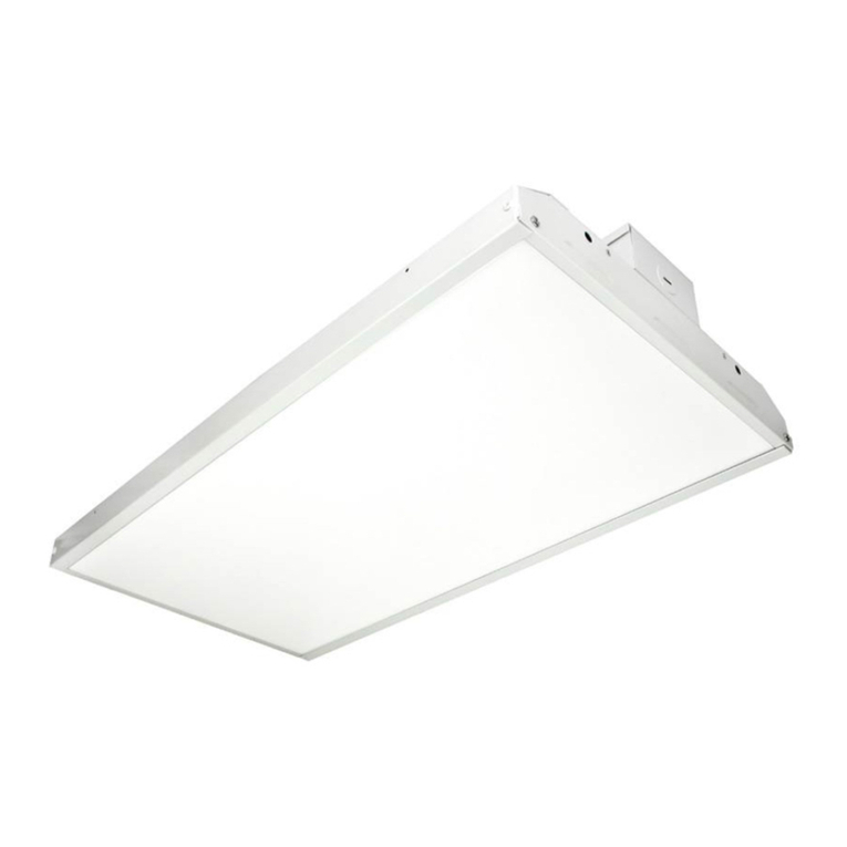
MaxLite LSV Series User manual

Operating Instructions LSV Series
MaxLite 8ft Vapor Tight - LSV Series
®
General Safety Information
• To reduce the risk of death, personal injury or property damage from fire,
electric shock, falling parts, cuts/abrasions, and other hazards read all
warnings and instructions included with and on the fixture box and all
fixture labels.
• Before installing, servicing, or performing routine maintenance upon
this equipment, follow these general precautions.
• Commercial installation, service and maintenance of luminaires
should be performed by a qualified licensed electrician.
• or Residential installation: If you are unsure about the installation or
maintenance of the luminaires, consult a qualified licensed electrician
and check your local electrical code.
• To prevent wiring damage or abrasion, do not expose wiring to edges of sheet
metal or other sharp objects.
• Do not make or alter any open holes in an enclosure of wiring or electrical
components during kit installation.
• DO NOT INSTALL DAMAGED PRODUCT!
• Suitable for Dry or Damp location
WARNING:
RIS OF ELECTRICAL SHOC
• Turn off electrical power at fuse or circuit breaker box before wiring fixture
to the power supply.
• Turn off the power when you perform any maintenance.
• Verify that supply voltage is correct by comparing it with the luminaire label
information.
• Make all electrical and grounded connections in accordance with the National Electrical
Code and any applicable local code requirements.
• All wiring connections should be capped with UL approved wire connectors.
CAUTION:
RIS OF INJURY
• Wear gloves and safety glasses at all times when removing luminaire from carton, installing,
servicing or performing maintenance.
• Avoid direct eye exposure to the light source while it is on.
• Account for small parts and destroy packing material, as these may be hazardous to children.
CAUTION:
RIS OF FIRE
• eep combustible and other materials that can burn away from luminaire and lamp/lens.
NOTE: Green ground screw provided in proper location.
Do not relocate.
NOTE: Minimum 90° supply conductors.
NOTE: Specifications and dimensions subject to change without
notice.
NOTE: Suitable for Dry or Damp location.
Models:
This instruction manual applies to the LSV Series
Picture is for illustration purposes
only. Your model may vary.
© Copyright 2021 MaxLite, Inc. All Rights Reserved.
12 York Ave, West Caldwell, NJ 07006 Tel: 800-555-5629 ax: 973-244-7333 Email: info@maxlite.com
Page: 1
REV: 10/29/21
Included in the box:
• LSV Vapor Tight ixture
• Instructions
• Brackets (3)
• V-Hooks (3) & hardware

Setting Wattage & Color Temperature
Note: Applicable to models ending in WCS only. Models are set to lowest wattage and 4000K.
L
M
H
3500K
4000K
5000K
Color settings:
Left, stands for 3500K;
Middle, stands for 4000K;
Right, stands for 5000K;
Wattage settings:
Left, stands for Low;
Middle, stands for Medium;
Right, stands for High;
The end users may adjust the color temperature and lumen output respectively by the two DIP switch. Each DIP
switch is accommodated with 3 options (left, middle and right ), corresponding to 3 color temperatures and 3
powers respectively, which can perform the desired color temperature and lumen output combination.
1. DIP switches are located onto the side of the fixture.
2. Select a wattage and color temperature by sliding switch left or right respectively to the desired value.
Wattage Switch
CCT Switch
Operating Instructions LSV Series
MaxLite 8ft Vapor Tight - LSV Series
®
© Copyright 2021 MaxLite, Inc. All Rights Reserved.
12 York Ave, West Caldwell, NJ 07006 Tel: 800-555-5629 ax: 973-244-7333 Email: info@maxlite.com
Page: 2
REV: 10/29/21

General Wiring Diagram
CAUTION: Turn off electrical power at fuse
or circuit breaker box before wiring fixture to
the power supply.
Input Rating: 120-277V 50/60 Hz
Black = Line
White = Neutral
Green = Ground
TO SOURCE
120V-277V
GREEN (GROUND)
BLAC (LINE)
WHITE (NEUTRAL)
REDBLUEPURPLE GREY/
PIN
LED DRIVER
+--+
(LEAD WIRES TO LED LOAD)
(DIMMING WIRE TO 0-10V
IEC COMPLIANT CONTROL)
Surface Mounting Installation Instructions
Operating Instructions LSV Series
MaxLite 8ft Vapor Tight - LSV Series
®
1. Locate drill holes for mounting brackets. Use hardware found in hardware kit. Mount bracket to surface.
2. Secure mounting clips to housing recesses by firmly pressing them into place until both
sides of the clip are secured.
3. Release latches by pulling top of
latch away from housing.
4. Without touching LED boards,detach LED
tray from fixture.
© Copyright 2021 MaxLite, Inc. All Rights Reserved.
12 York Ave, West Caldwell, NJ 07006 Tel: 800-555-5629 ax: 973-244-7333 Email: info@maxlite.com
Page: 3
REV: 10/29/21

Operating Instructions LSV Series
MaxLite 8ft Vapor Tight - LSV Series
®
Surface Mounting Installation Instructions (Continued)
outlet box cover
ground wire
5. Locate safety cable when opening to install fixture body and Snap connect tether to gear tray before
making electrical connection as shown in figure.
6. Connect power supply to the driver through
the outlet box as shown in the figure (the
flexible cord is customer supplied), make
sure to snap the cover to the outlet box after
wiring is completed.
7. ollow the general wiring diagram above for
reference. Make sure that the power supply
is disconnected before installing.
© Copyright 2021 MaxLite, Inc. All Rights Reserved.
12 York Ave, West Caldwell, NJ 07006 Tel: 800-555-5629 ax: 973-244-7333 Email: info@maxlite.com
Page: 4
REV: 10/29/21

Operating Instructions LSV Series
MaxLite 8ft Vapor Tight - LSV Series
®
© Copyright 2021 MaxLite, Inc. All Rights Reserved.
12 York Ave, West Caldwell, NJ 07006 Tel: 800-555-5629 ax: 973-244-7333 Email: info@maxlite.com
Page: 5
REV: 10/29/21
Surface Mounting Installation Instructions (Continued)
8. Reattach LED tray to fixture by reversing step 4. 9. Secure lens to housing with lens latches.
Note:
• Connect the flexible cord (SJTW 18AWG) to the junction box, and cover the junction box with the UL listed
canopy. Make sure to provide a strain relief at the canopy side.
• Ensure that the gap is sealed with glue.
• Be sure to provide with a wet location rated strain relief.
Chain Suspended Mounting Installation Instructions
1. Attach V-bracket to each mounting clip by
spreading the ends of the V-bracket apart
and then inserting the legs into the holes in
the side of the mounting clips.
2. Secure mounting clips to housing recesses
by firmly pressing them into place until both
sides of the clip are secured. Hang fixture
from customer supplied chain using
V-brackets.

Operating Instructions LSV Series
MaxLite 8ft Vapor Tight - LSV Series
®
© Copyright 2021 MaxLite, Inc. All Rights Reserved.
12 York Ave, West Caldwell, NJ 07006 Tel: 800-555-5629 ax: 973-244-7333 Email: info@maxlite.com
Page: 6
REV: 10/29/21
Chain Suspended Mounting Installation Instructions (Continued)
3. Hang fixture from customer supplied chain
using V-brackets.
4. Release latches by pulling top of latch away
from housing.
5. Without touching LED boards,detach LED tray
from fixture.
6. Locate safety cable when opening to install
fixture body and snap connect tether to gear
tray before making electrical connection as
shown in figure.

Operating Instructions LSV Series
MaxLite 8ft Vapor Tight - LSV Series
®
© Copyright 2021 MaxLite, Inc. All Rights Reserved.
12 York Ave, West Caldwell, NJ 07006 Tel: 800-555-5629 ax: 973-244-7333 Email: info@maxlite.com
Page: 7
REV: 10/29/21
Chain Suspended Mounting Installation Instructions (Continued)
outlet box cover
ground wire
7. Connect power supply to the driver through the
outlet box as shown in the figure (the flexible cord
is customer supplied), make sure to snap the
cover to the outlet box after wiring is completed.
8. ollow the general wiring diagram above for
reference. Make sure that the power supply is
disconnected before installing.
9. Reattach LED tray to fixture by reversing step 5. 10. Secure lens to housing with lens latches.

Motion Sensor Model Install Instructions (Additional Accessory)
ANT-3A
DIM TO OFF
DRIVER
Black
White
+
_
Yellow
Brown
Purple
Gray/Pink
Red
Blue
L
N
LED
DIM
12VDC
LED light source
Green
LED +
_
+
_
DIM
12VDC
Sensor
Operating Instructions LSV Series
MaxLite 8ft Vapor Tight - LSV Series
®
Wiring Diagram
© Copyright 2021 MaxLite, Inc. All Rights Reserved.
12 York Ave, West Caldwell, NJ 07006 Tel: 800-555-5629 ax: 973-244-7333 Email: info@maxlite.com
Page: 8
REV: 10/29/21

Operating Instructions LSV Series
MaxLite 8ft Vapor Tight - LSV Series
®
© Copyright 2021 MaxLite, Inc. All Rights Reserved.
12 York Ave, West Caldwell, NJ 07006 Tel: 800-555-5629 ax: 973-244-7333 Email: info@maxlite.com
Page: 9
REV: 10/29/21
Emergency Battery Backup Model Install Instructions (Additional Accessory)
Emergency driver Battery
Led driver Test switch
LED DRIVER
Purple
Gray/Pink
Red
Blue
Black
White
LED
White
+
_
_
Connector
BATTERY
LED
LED
_
_
+
+
_L
N
AC
AC
Black
Red
Connector
Black
Red
EMERGENCY
Gray/Pink
White
Red
Black
3500K
5000K
White
Black
Black/White
Brown
Purple
Brown
Purple
TEST SWITCH
Connector
Connector
L
N
Green
LED DRIVER
Purple
Gray/Pink
Red
Blue
Black
White
LED
White
+
_
_
Connector
BATTERY
LED
LED
_
_
+
+
_L
N
AC
AC
Black
Red
Connector
Black
Red
EMERGENCY
Gray/Pink
White
Red
Black
3500K
5000K
White
Black
Black/White
Brown
Purple
Brown
Purple
TEST SWITCH
Connector
Connector
L
N
Green
If emergency color
temperature is 5000K
If emergency color
temperature is 3500K
Wiring Diagram

Operating Instructions LSV Series
MaxLite 8ft Vapor Tight - LSV Series
®
© Copyright 2021 MaxLite, Inc. All Rights Reserved.
12 York Ave, West Caldwell, NJ 07006 Tel: 800-555-5629 ax: 973-244-7333 Email: info@maxlite.com
Page: 10
REV: 10/29/21
Emergency Battery Back-up+Microwave Motion Sensor (Additional Accessory)
LED DRIVER
Black
White
+
_
+
_
+
_
Yellow
Brown
Purple
Gray/Pink
Red
Blue
Yellow
Purple
Gray/Pink
+
_
+
L
N
EMERGENCY LED DRIVER
White
Black
Black/White Gray/Pink
White
Red
Black
Brown
Purple
Brown
Purple
TEST SWITCH
BATTERY
LED
Gray/Rose +
_
White
SENSOR
Wiring Diagram
Models with c-Max™ Sensor

Operating Instructions LSV Series
MaxLite 8ft Vapor Tight - LSV Series
®
© Copyright 2021 MaxLite, Inc. All Rights Reserved.
12 York Ave, West Caldwell, NJ 07006 Tel: 800-555-5629 ax: 973-244-7333 Email: info@maxlite.com
Page: 11
REV: 10/29/21
CEA-RDW Adapter Installation Instructions
1. Remove the lens and the LED board to expose the LED driver. Drill a hole on one of the ends using the ½”
knockout hole pattern on the fixture.
2. Run the wires from the adapter through the knock out hole of the fixture and attach the adapter using the
locking nut. Ensure that the adapter is facing downwards after the fixture is installed.
3. Connect the wires according to the general wiring diagram ( IG). Re-attach the LED board and the lens to
the fixture.
General Wiring Diagram
0-10V DIM LED Driver
Purple
Gray/Pink
Yellow
Vaux+Vaux-
DIM-
(Gray/Pink)
DIM+ (Purple)
LED- (Black)
LED+ (Red)
L
N
GND
Fixture
Lock Nut
Adapter
CAUTION: Turn off electrical power at fuse or circuit breaker box before wiring fixture to the power supply.

10-Year standard warranty with labor allowance*
(see terms at www.maxlite.com/warranties)
*Warranty Limitations: Product must be rated for application per the Product Data Sheet (PDS); operated ≤16 hrs;
in ambient temperatures -4° to 77° .
*Up to $25/unit; registration required. Additional coverage may be available for purchase; contact MaxLite.
*Excludes EM/MS versions; component warranty applies.
*If ambient temperatures fall outside the -4° to 77° range; product is warrantied for 5 years according to the
operating temperature range specified on the PDS.
Limitation of Liability
THE OREGOING WARRANTY IS EXCLUSIVE, AND IS THE SOLE REMEDY OR ANY AND ALL CLAIMS,
WHETHER IN CONTRACT, IN TORT OR OTHERWISE ARISING ROM THE AILURE O PRODUCT AND IS IN
LIEU O ALL OTHER WARRANTIES, EXPRESS OR IMPLIED, INCLUDING ALL WARRANTIES O
MERCHANTABILITY OR ITNESS OR A PARTICULAR PURPOSE, WHICH WARRANTIES ARE HEREBY
EXPRESSLY DISCLAIMED TO THE EXTENT PERMITTED BY LAW AND, IN ANY EVENT, SHALL BE LIMITED TO
THE WARRANTY PERIOD SPECI IED ABOVE. THE LIABILITY O MAXLITE SHALL BE LIMITED TO THE TERMS
O THE EXPRESS WARRANTY SET ORTH HEREIN. IN NO EVENT WILL MAXLITE BE LIABLE OR ANY
SPECIAL, INCIDENTAL OR CONSEQUENTIAL DAMAGES INCLUDING, WITHOUT LIMITATION, DAMAGES
RESULTING ROM LOSS O USE, PRO ITS, BUSINESS OR GOODWILL, LABOR COSTS, REMOVAL OR
INSTALLATION COSTS, DECREASE IN THE LIGHT OUTPUT O THE LAMP, AND/OR DETERIORATION IN THE
LAMP’S PER ORMANCE, WHETHER OR NOT MAXLITE HAS BEEN ADVISED O THE POSSIBILITY THEREO .
UNDER NO CIRCUMSTANCES SHALL MAXLITE’S ENTIRE LIABILITY OR A DE ECTIVE PRODUCT EXCEED
THE PURCHASE PRICE O THAT PRODUCT. WARRANTY SERVICES PROVIDED UNDER THESE TERMS AND
CONDITIONS DO NOT ENSURE THE UNINTERRUPTED OPERATION O PRODUCTS; MAXLITE SHALL NOT BE
LIABLE OR DAMAGES CAUSED BY ANY DELAYS INVOLVING WARRANTY SERVICE.
This Limited Warranty gives you specific legal rights and you may also have other rights that may vary from state to
state. Because some states or jurisdictions do not allow the exclusion or limitation of liability for consequential or
incidental damages, this limitation may not apply to you.
Warranty Information
Operating Instructions LSV Series
MaxLite 8ft Vapor Tight - LSV Series
®
© Copyright 2021 MaxLite, Inc. All Rights Reserved.
12 York Ave, West Caldwell, NJ 07006 Tel: 800-555-5629 ax: 973-244-7333 Email: info@maxlite.com
Page: 12
REV: 10/29/21

Mode d’emploi Série LSV
MaxLite de 244cm (8 pi) étanche à la vapeur - Série LSV
®
Consignes générales de sécurité
• Pour réduire le risque de décès, de blessure corporelle ou de dommage
matériel provoqué par incendie, choc électrique, chute d’objets,
coupures / abrasions et autres risques, lisez tous les avertissements
et les instructions qui accompagnent l’emballage du luminaire et toutes
les étiquettes du luminaire.
• Avant l’installation, la réparation ou la réalisation des opérations ordinaires
d’entretien de cet équipement, suivez ces précautions générales.
• L’installation commerciale, la réparation et l’entretien des luminaires seront
effectués par un électricien qualifié et autorisé.
• Pour l’installation résidentielle: Si vous avez des doutes concernant l’installation ou l’entretien des
luminaires, veuillez consulter un électricien qualifié et autorisé et vérifiez les dispositions du code
électrique local.
• Pour prévenir les dommages de câblage ou l’abrasion, ne pas exposer le câblage aux bordures de
tôle ou aux autres objets tranchants.
• Ne pas réaliser ou modifier de trous dans une enceinte de câblage ou de composants électriques
pendant l’installation de ce kit.
• NE PAS INSTALLER DE PRODUITS ENDOMMAGÉS!
• Convient aux endroits secs ou humides
AVERTISSEME T: RISQUE DE CHOC ÉLECTRIQUE
• Débrancher l’alimentation électrique au fusible ou au disjoncteur avant de connecter le
luminaire à la source d’alimentation.
• Débranchez l’alimentation lorsque vous effectuez des travaux d’entretien.
• Vérifiez si la valeur de la tension d’alimentation est correcte en la comparant aux informations
dans le tableau sur l’étiquette du luminaire.
• Réalisez toutes les connexions électriques et de terre en conformité avec le code électrique
national et les éventuelles exigences locales applicables du code.
• Toutes les connexions électriques seront terminées avec des connecteurs pour fils approuvés UL.
PRÉCAUTIO : RISQUE DE BLESSURE
• Portez des gants et des lunettes de sécurité en tout temps, lorsque vous enlevez le luminaire
de son emballage, lors de l’installation, la réparation ou les travaux d’entretien.
• Évitez l’exposition directe des yeux à la source de lumière si le luminaire est allumé.
• Comptabilisez les composants de dimensions réduites et éliminez l’emballage, parce qu’il peut
représenter un risque pour les enfants.
PRÉCAUTIO : RISQUE D’I CE DIE
• Gardez les matériaux combustibles et les autres matériaux qui peuvent brûler à distance des
luminaires et de la lampe/lentille.
REMARQUE: Vis verte de terre fournie à l’endroit adéquat. e pas déplacer.
REMARQUE: Conducteurs d’alimentation min 90°.
REMARQUE: Les spécifications et les dimensions peuvent
changer sans préavis.
REMARQUE: Convient aux endroits secs ou humides.
Modèles:
Ce manuel d’instructions s’applique à la série LSV.
L’image est pour des fins
d’illustration seulement. Votre
modèle peut être différent.
© Droits d’auteur 2021 MaxLite, Inc. Tous droits réservés.
12 York Ave, West Caldwell, NJ 07006 Tél: 800-555-5629 ax: 973-244-7333 Email: inf[email protected]
Page: 1
REV: 10/29/21
Included in the box:
• Luminaire LSV étanche
à la vapeur
• Instructions
• Support (3)
• Crochets en V (3)
& matériel

Réglage de la puissance et de la température de couleur:
Remarque: Applicable uniquement aux modèles terminés en WCS. Les modèles sont configurés à
la puissance la moins élevée et à 4000K.
L
M
H
3500K
4000K
5000K
Réglages de la couleur:
La gauche correspond à 3500K;
le milieu correspond à 4000K;
la droite correspond à 5000K;
Réglages de la puissance:
La gauche correspond au
niveau réduit; le milieu
correspond au niveau
moyen; la droite
correspond au niveau élevé;
Les utilisateurs finaux peuvent régler la température de couleur et le rendement lumineux respectivement en utilisant
les deux commutateurs DIP. Chaque commutateur DIP a 3 options (gauche, milieu et droite), correspondant à 3
températures de couleur et à 3 niveaux de puissance respectivement, qui peut effectuer la combinaison désirée de
température de couleur et rendement lumineux.
1. Les commutateurs DIP sont situés sur le côté du luminaire.
2. Sélectionner une puissance et une température de couleur en faisant glisser le commutateur vers la gauche ou
vers la droite respectivement pour la valeur désirée.
Commutateur de la puissance
Commutateur TCP
Mode d’emploi Série LSV
MaxLite de 244cm (8 pi) étanche à la vapeur - Série LSV
®
© Droits d’auteur 2021 MaxLite, Inc. Tous droits réservés.
12 York Ave, West Caldwell, NJ 07006 Tél: 800-555-5629 ax: 973-244-7333 Email: inf[email protected]
Page: 2
REV: 10/29/21

Schéma général de câblage
PRÉCAUTIO : Débrancher l’alimentation
électrique au fusible ou au disjoncteur avant
de connecter le luminaire à la source
d’alimentation.
Tension d’entrée nominale: 120-277V 50/60 Hz
Noir = Phase
Blanc = Neutre
Vert = Terre
À LA
SOURCE
120V-277V VERT (TERRE)
OIR (PHASE)
BLA C ( EUTRE)
ROUGEBLEUVIOLET GRIS/
ROSE
PILOTE LED
+--+
(FILS D’ALIME TATIO LED)
(FIL DE VARIATEUR 0-10V
COMMA DE CO FORME IEC)
Instructions d’installation en surface
1. Trouver les trous de forage pour les supports de montage. Utiliser le matériel trouvé
dans le kit de matériel. Monter le support sur la surface.
2. ixer les pinces de montage dans les encoches du boîtier en les appuyant fermement
en place jusqu’à ce que les deux côtés de la pince soient fixées.
3. Libérer les loquets en éloignant la
partie supérieure du loquet du boîtier. 4. Sans toucher les planches à LED,
détacher le plateau à LED du luminaire.
Mode d’emploi Série LSV
MaxLite de 244cm (8 pi) étanche à la vapeur - Série LSV
®
© Droits d’auteur 2021 MaxLite, Inc. Tous droits réservés.
12 York Ave, West Caldwell, NJ 07006 Tél: 800-555-5629 ax: 973-244-7333 Email: inf[email protected]
Page: 3
REV: 10/29/21

Instructions d’installation en surface (suite)
boîtier de sortie couvercle
fil de terre
5. Localiser le câble de sécurité lors de l’ouverture pour installer le corps du luminaire et connecter le
câble au plateau du matériel avant d’effectuer les connexions électriques comme illustré dans la figure.
6. Connecter le câble d’alimentation au pilote à
travers le boîtier de sortie comme illustré dans
la figure (le cordon flexible est fourni par le
client), s’assurer de remettre le couvercle du
boîtier de sortie après avoir réalisé le câblage.
7. Respecter le schéma général de câblage
ci-dessus pour référence. S’assurer que
l’alimentation électrique est déconnectée
avant l’installation.
Mode d’emploi Série LSV
MaxLite de 244cm (8 pi) étanche à la vapeur - Série LSV
®
© Droits d’auteur 2021 MaxLite, Inc. Tous droits réservés.
12 York Ave, West Caldwell, NJ 07006 Tél: 800-555-5629 ax: 973-244-7333 Email: inf[email protected]
Page: 4
REV: 10/29/21

Instructions d’installation en surface (suite)
8. Rattacher le plateau à LED au luminaire en
suivant l’étape 4 en ordre inverse. 9. Attacher la lentille au boîtier avec les loquets
de lentille.
Remarque:
• Connecter le cordon flexible (SJTW 18AWG) au boîtier de jonction et couvrir le boîtier de jonction avec le
couvercle homologué UL. S’assurer de fournir un moyen de soulagement de traction sur le côté du couvercle.
• S’assurer d’étanchéiser l’espace avec de l’adhésif.
• S’assurer de fournir un moyen de soulagement de traction qui convient aux endroits humides.
Instructions d’installation suspendue par chaînes
1. Attacher le support en V à chaque pince de
montage en écartant les bouts du support en
V et en insérant ensuite les jambes dans les
trous sur les côtés des pinces de montage.
2. ixer les pinces de montage dans les
encoches du boîtier en les appuyant
fermement en place jusqu’à ce que les deux
côtés de la pince soient fixées. Accrocher le
luminaire avec la chaîne fournie par le client à
l’aide des supports en V.
© Droits d’auteur 2021 MaxLite, Inc. Tous droits réservés.
12 York Ave, West Caldwell, NJ 07006 Tél: 800-555-5629 ax: 973-244-7333 Email: inf[email protected]
Page: 5
REV: 10/29/21
Mode d’emploi Série LSV
MaxLite de 244cm (8 pi) étanche à la vapeur - Série LSV
®

Instructions d’installation suspendue par chaînes (suite)
3. Accrocher le luminaire avec la chaîne fournie
par le client à l’aide des supports en V. 4. Libérer les loquets en éloignant la partie
supérieure du loquet du boîtier.
5. Sans toucher les planches à LED, détacher le
plateau à LED du luminaire. 6. Localiser le câble de sécurité lors de l’ouverture
pour installer le corps du luminaire et connecter
le câble au plateau du matériel avant d’effectuer
les connexions électriques comme illustré dans
la figure.
Mode d’emploi Série LSV
MaxLite de 244cm (8 pi) étanche à la vapeur - Série LSV
®
© Droits d’auteur 2021 MaxLite, Inc. Tous droits réservés.
12 York Ave, West Caldwell, NJ 07006 Tél: 800-555-5629 ax: 973-244-7333 Email: inf[email protected]
Page: 6
REV: 10/29/21

Instructions d’installation suspendue par chaînes (suite)
boîtier de sortie couvercle
fil de terre
7. Connecter le câble d’alimentation au pilote à
travers le boîtier de sortie comme illustré dans la
figure (le cordon flexible est fourni par le client),
s’assurer de remettre le couvercle du boîtier de
sortie après avoir réalisé le câblage.
8. Respecter le schéma général de câblage
ci-dessus pour référence. S’assurer que
l’alimentation électrique est déconnectée avant
l’installation.
9. Rattacher le plateau à LED au luminaire en
suivant l’étape 5 en ordre inverse. 10. Attacher la lentille au boîtier avec les loquets
de lentille.
Mode d’emploi Série LSV
MaxLite de 244cm (8 pi) étanche à la vapeur - Série LSV
®
© Droits d’auteur 2021 MaxLite, Inc. Tous droits réservés.
12 York Ave, West Caldwell, NJ 07006 Tél: 800-555-5629 ax: 973-244-7333 Email: inf[email protected]
Page: 7
REV: 10/29/21

Instructions d’installation du modèle à capteur de mouvement (accessoire supplémentaire)
ANT-3A
VAR SUR ARRÊT
PILOTE
Noir
Blanc
+
_
Jaune
Marron
Violet
Gris/Rose
Rouge
Bleu
L
N
LED
VAR
12VCC
Source de lumière
à LED
Vert
LED +
_
+
_
VAR
12VCC
Capteur
Schéma de câblage
Mode d’emploi Série LSV
MaxLite de 244cm (8 pi) étanche à la vapeur - Série LSV
®
© Droits d’auteur 2021 MaxLite, Inc. Tous droits réservés.
12 York Ave, West Caldwell, NJ 07006 Tél: 800-555-5629 ax: 973-244-7333 Email: inf[email protected]
Page: 8
REV: 10/29/21
This manual suits for next models
2
Table of contents
Languages:
Other MaxLite Light Fixture manuals
Popular Light Fixture manuals by other brands

Cooper Lighting
Cooper Lighting Halo L5056 Stasis specification

Philips
Philips 69112-31-PH Specification sheet

Good Earth Lighting
Good Earth Lighting UC1208-AL3-12LF5-G quick start guide

Lightolier
Lightolier ALETTA AL2T8 specification

Triarch
Triarch 2 LTS Flushmount Fixture 31446 Assembly instruction

RIB
RIB SPARK Wi-Fi manual