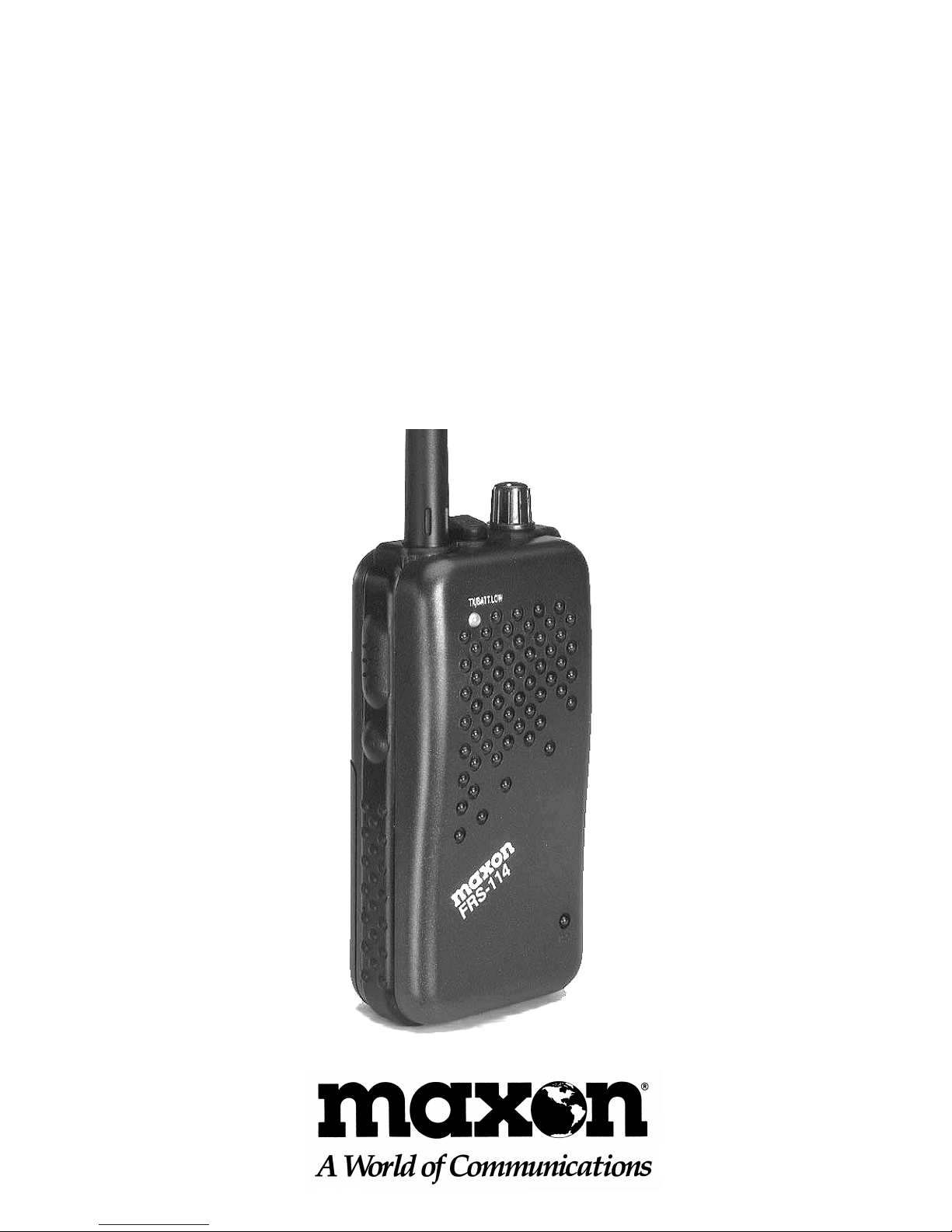
Maxon FRS-114 User manual

FRS-114
Family Radio Service
UHF Two-Way Radio
OWNER'S MANUAL
English/Spanish

TABLE OF CONTENTS
FRS Product Description 1
Package Contents 2
Controls and Functions 3
Programming Instructions 6
Operating Instructions 8
Charging Ni-Cad Batteries 10
Specifications 11
Warranty Service Instructions 12
Warranty Statement 13
Maxon Accessories 15
Other Maxon Products 15

TABLA DE CONTENIDO
Controles y Funciones 3
FRS Descripción del Producto 16
Contenido del Paquete 17
Instrucciones de Programación 18
Instrucciones de Operación 20
Para Cargar Baterías Ni-Cad 22
Especificaciones 23
Instrucciones Servicio
de Garantía 24
Aclaración de la Garantía 25
Accesorios Maxon 27
Otros Productos Maxon 27

FRS PRODUCT DESCRIPTION
The Family Radio Service (FRS) is the newest
generation in personal two-way communica-
tions. FRS radios operate in a license-free
band (no FCC license for operation) on one of
14 license-free channels.
Maxon's FRS-114 is a lightweight, palm-
sized two-way radio that you can carry
almost anywhere. Use it at shopping malls,
sporting events, amusement parks... any
indoor or outdoor activity! The radio
communicates up to 2 miles* - allowing you
to keep in touch with family, friends or a
neighborhoodwatchgroup.
The FRS-114 is a single channel model
with the capability of all 14 FRS channels.
You can talk to another person using any
FRS radio, provided that you are on the
same frequency. Channel programming
is described in this manual.
The radio has an automatic battery saver
feature -- at 8 seconds of non-use the radio
goes into power save, assuring longer battery
life.
* Range will vary, depending on terrain and environment.
1

PACKAGE CONTENTS
FRS-114 Radio with Belt Clip
Screw-in "Rubber Duck" Antenna
Owner's Manual
2

3
CONTROLS AND FUNCTIONS
CONTROLES Y FUNCIONES
A. Monitor Button - Checks activity on the channel,
and permits the radio to monitor weak signals
• Botón de Monitoreo - Observa la actividad en el
canal y permite al radio monitorear las señales
débiles
B. Push-To-Talk Button - Permits radio transmissions
• Botón "Presione Para Hablar" (P-T-T) - Permite la
transmisión por radio
C. Transmit/Battery Low LED - Indicates active
transmissions and alerts user to low battery condition
• LED Muestra Transmisión/ Batería Baja - Indica
transmisiónes activas y alerta al usuario cuando la
batería tiene carga baja
D. Antenna • Antena
E. Ear Speaker Jack - Used with an ear speaker for
private audio reception • Conector de Microfóno
Para Oido - Se usa para recepcion privada
de audio
F. Off/On-Volume Control - Used to turn the radio on
or off and adjust the listening volume • Control de
Volúmen - Se usa para encender o apagar el radio y
para ajustar el volúmen
G. Microphone - Transmits voice signals • Microfóno -
Transmite señal de voz
H. Channel Programming Dip Switches - Used to
program the radio channel frequency (located within
battery compartment) • Programacion de Canels via
Interruptor - Se usa para programar la frecuencia de
canales en el radio (localizado a un lado de
compartimento para baterías)

4
E F
D
C
B
A
G
J
I
HK

5
I. Charge Jack - Used to charge ni-cad batteries inside
the unit - requires optional Maxon DV-7510 AC/DC
wall charger (located on side of unit) • Conector
Para Cargador - Se usa para cargar baterías ni-cad de
ntro de la unidad. Se requiere el modelo opcional
Maxon DV-7510 AC/DC cargador de pared
(localizado en la parte trasera de la unidad)
J. Belt Clip - Used to secure the radio to a belt, or
another convenient location • Grapa de Centurón -
Se usa para llevar el radio en el cinturón o en
cualquier otra parte conveniente
K. Battery Compartment - Houses 4 AAA size batteries
(located on back of unit) • Compartimento para
Baterías - Contiene 4 baterías AAA (localizado en la
parte trasera de la unidad)

6
PROGRAMMINGINSTRUCTIONS
Remove the battery compartment door.
BEFORE INSTALLING BATTERIES,locate
the channel programming dip switches at
the upper left corner. To select an operating
channel, move the switches per the chart
below (we suggest you use a pointed utensil
like a ball point pen). All radios must be on
the same frequency to communicate with
each other. NOTE: Switch 5 is not used in
programming.
Example of dip switches set for Channel 9:
Switch: 1/down 2/down 3/down 4/up
Channel 1* - Frequency 462.5625 MHz
Switch: 1/up 2/up 3/up 4/up
Channel 1* - Frequency 462.5625 MHz
Switch: 1/down 2/up 3/up 4/up
Channel 1* - Frequency 462.5625 MHz
Switch: 1/down 2/down 3/down 4/down
*NOTE: There are three combinations for Channel
1, any can be used.
1 2 3 4 5

7
Channel 2 - Frequency 462.5875 MHz
Switch: 1/up 2/down 3/down 4/down
Channel 3 - Frequency 462.6125 MHz
Switch: 1/down 2/up 3/down 4/down
Channel 4 - Frequency 462.6375 MHz
Switch: 1/up 2/up 3/down 4/down
Channel 5 - Frequency 462.6625 MHz
Switch: 1/down 2/down 3/up 4/down
Channel 6 - Frequency 462.6875 MHz
Switch: 1/up 2/down 3/up 4/down
Channel 7 - Frequency 462.7125 MHz
Switch: 1/down 2/up 3/up 4/down
Channel 8 - Frequency 467.5625 MHz
Switch: 1/up 2/up 3/up 4/down
Channel 9 - Frequency 467.5875 MHz
Switch: 1/down 2/down 3/down 4/up
Channel 10 - Frequency 467.6125 MHz
Switch: 1/up 2/down 3/down 4/up
Channel 11 - Frequency 467.6375 MHz
Switch: 1/down 2/up 3/down 4/up
Channel 12 - Frequency 467.6625 MHz
Switch: 1/up 2/up 3/down 4/up
Channel 13 - Frequency 467.6875 MHz
Switch: 1/down 2/down 3/up 4/up
Channel 14 - Frequency 467.7125 MHz
Switch: 1/up 2/down 3/up 4/up

OPERATINGINSTRUCTIONS
Install 4 new AAA size batteries, aligning
the polarity by the diagram embossed into the
cabinet. The (-) flat bottom of the battery rests
on the spring, and the (+) top contacts the
metal plate. Refer to drawing below for proper
battery installation. NOTE: Always remove
batteries if product will not be used for long
periods of time.
Diagram of battery polarity
Replace the battery compartment door.
Turn the power on by rotating the off/on-
volume control clockwise. The radio will
sound a melody tone to verify power. Adjust
to desired volume.
8
- + - +
+ - + -

9
To transmit, hold the radio 2-3 inches from
your mouth, press the push-to-talk button
on the radio side, and speak clearly into
the microphone area of the radio. For best
quality, speak slowly and in a normal tone
of voice. There is no need to speak loudly.
The button below the P-T-T bar is used
to monitor channel activity. This monitor
button (labeled MON) checks for distant,
or weak transmissions. Press and hold briefly
to check channel activity before you transmit.
When your transmission is complete, release
the P-T-T button and listen for a reply.
When not using the radio, conserve battery
power by turning the unit off. Rotate the off/
on-volume control counter-clockwise to
detent.
The Maxon FRS-114 is equipped with a ear
speaker jack on the top of the unit. When
used, a more private reception of a radio
message is possible. This jack will accept
Maxon's WTA-9F or most standard ear
speakers with a 3.5 mm plug size.

10
CHARGING NI-CAD BATTERIES
NOTE: RECHARGE NICKEL CADMIUM
BATTERIES ONLY. DO NOT attempt to
recharge alkaline or carbon zinc batteries.
It may result in bodily injury and/or damage
to the product.
To charge ni-cad batteries inside the unit's
case, turn the radio off and plug the optional
Maxon DV-7510 AC/DC Wall Charger into
the charge jack (labeled CHG) on the side of
the radio. Ni-cad batteries should be charged
for 12-14 hours before initial use.
For maximum performance and to ensure
maximum range, always keep fresh batteries
in your radio. If you do not wish to recharge
the batteries periodically, use standard
alkaline or carbon zinc batteries.

11
FRS-114 SPECIFICATIONS
GENERAL
Operating Channels: 1
Total Number of
Channels Available: 14
Output Power: 0.5 Watts Direct Output
(FCC maximum)
Battery Life: 21 hours (typical)
Channel/Frequency: 1 462.5625MHz
2 462.5875MHz
3 462.6125MHz
4 462.6375MHz
5 462.6625MHz
6 462.6875MHz
7 462.7125MHz
8 467.5625MHz
9 467.5875MHz
10 467.6125 MHz
11 467.6375 MHz
12 467.6625 MHz
13 467.6875 MHz
14 467.7125 MHz

12
WARRANTY SERVICE
INSTRUCTIONS
1) Refer to the Operating Instructions section
of this Owner’s Manual for proper operation
and adjustments.
2) If the problem cannot be corrected by
reference to this Owner's Manual, return
the product with proof of purchase (a sales
receipt) to the place of purchase, or call
Maxon’s Customer Service Department for
assistance, 1-800-821-7848, Ext. 499.
FOR YOUR RECORDS
Purchase Date:
Purchased From:
Serial Number:
KEEP THIS INFORMATION
IN A SAFE PLACE

13
LIMITED WARRANTY STATEMENT
The Consumer Products Division of Maxon America,
Inc. (hereinafter referred to as “Maxon”), warrants that
its Products and their included accessories will be free
from defects in workmanship or materials under normal
use for a period of one (1) year from date of purchase
by the original end user, provided that the buyer has
complied with the requirements stated herein.
If the Product fails to function under normal use because
of manufacturing defect(s) or workmanship during the
one (1) year period following the date of purchase, it
will be replaced or repaired at Maxon’s option at no
charge when returned to the place of purchase. The
defective unit must be accompanied by proof of the
date of purchase in the form of a sales receipt.
Maxon’s sole obligation hereunder shall be to repair
or replace the Product covered in this Warranty.
Replacement, at Maxon’s option, may include a
similar or higher-featured product. Repair may
include the replacement of parts or boards with
functionally equivalent reconditioned or new parts
or boards. Replaced parts, accessories or boards are
warranted for the balance of the original time period.
All replaced parts, accessories or boards become the
property of Maxon America, Inc.
Maxon shall have no obligation to make repairs
or to cause replacement required through normal
wear and tear or necessitated in whole or in part by
catastrophe, fault or negligence of the user, improper

14
or unauthorized alterations or repairs to the Product, use
of the Product in a manner for which it was not designed,
or by causes external to the Product. This warranty is
void
if the serial number is altered, defaced or removed. The
purchaser shall provide for removal of the defective
Product and installation of its replacement.
THE EXPRESS WARRANTIES CONTAINED HEREIN
ARE IN LIEU OF ALL OTHER WARRANTIES,
EITHER EXPRESSED OR IMPLIED, OR STATUTORY,
INCLUDING, WITHOUT LIMITATION, ANY
WARRANTY OF MERCHANTABILITY OR FITNESS
FOR A PARTICULAR PURPOSE.
FOR ANY PRODUCT THAT DOES NOT COMPLY
WITH THE WARRANTY SPECIFIED, THE SOLE
REMEDY WILL BE REPAIR OR REPLACEMENT. IN
NO EVENT WILL MAXON AMERICA, INC. BE LIABLE
TO THE BUYER FOR ANY DAMAGES, INCLUDING
ANY SPECIAL, INCIDENTAL, INDIRECT OR CONSE-
QUENTIAL DAMAGES, OR THE LOSS OF USE OF,
OR THE INABILITY TO USE THE PRODUCT.
This warranty is void for sales and deliveries outside of
the U.S.A.

15
OPTIONAL / REPLACEMENT
MAXON ACCESSORIES
DV-7510 AC/DC Wall charger
WTA-9F Ear speaker
Rely on Maxon
for quality, value-priced
consumerelectronics!
MCB-10A Unique, detachable 40
channel CB transceiver
permits multi-vehicle use
49-FX 5 Channel two-way
radio features a choice of
push-to-talk or handsfree
operation
WX-70 7 Channel weather
receiver has a choice of 3
warning signal modes

FRS DESCRIPCIÓN DEL PRODUCTO
Servicio de Radio Familiar (FRS) es la nueva
generación en la comunicación personal de
dos vías. Los radios FRS operan en banda con
licencia liberada, (esta operación no requiere
licencia de FCC) en uno de los 14 caneles
libres de licencia.
El modelo FRS-114 de Maxon es un radio
de dos vías que uno puede llevar consigo a
todas partes, es ligero de peso, tamaño de
la palma de una mano. Puede usarse en
lugares de compras, eventos deportivos,
parques de atracciones, actividades interiores
o exteriores. El radio tiene un alcance de
hasta dos millas para mantenerse en contacto
con la familia, amigos o con el grupo
encargado de la vigilancia.
El FRS-114 es un modelo de un solo canal con
capacidad a todos los 14 caneles FRS. Uno
puede hablar con otra persona que esta usando
cualquiera radio FRS, siempre y cuando ambos
radio operan en la misma frecuencia. La
programmación de canales está descrito en
este manual.
* Alcance varía, según el terreno y alrededores.
16

17
CONTENIDO DEL PAQUETE
Un Radio FRS-114 con Grapa de Cinturón
Antena flexible de hule con conector de
rosca de hilos
Manual del Dueño
Table of contents
Languages:
Other Maxon Two-way Radio manuals

Maxon
Maxon GMRS-50 User manual

Maxon
Maxon FRS-100 User manual

Maxon
Maxon SP-1402 User manual

Maxon
Maxon SP-200K Series User manual

Maxon
Maxon SL-7402 Parts list manual

Maxon
Maxon SM-4450 User manual

Maxon
Maxon TPD-8000 Series User manual

Maxon
Maxon GMRS-50 Manual

Maxon
Maxon TPD-8124 User manual

Maxon
Maxon TK14-VWX User manual

Maxon
Maxon SP-100 User manual

Maxon
Maxon SL25 User manual

Maxon
Maxon TP-8000 User manual

Maxon
Maxon TSD-4000 Series User manual

Maxon
Maxon SP-200 Series User manual

Maxon
Maxon GMRS-21X User manual

Maxon
Maxon S5 PMR446 User manual

Maxon
Maxon PM100 User manual

Maxon
Maxon SP-300 Series User manual

Maxon
Maxon S5E PMR446 User manual