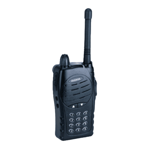
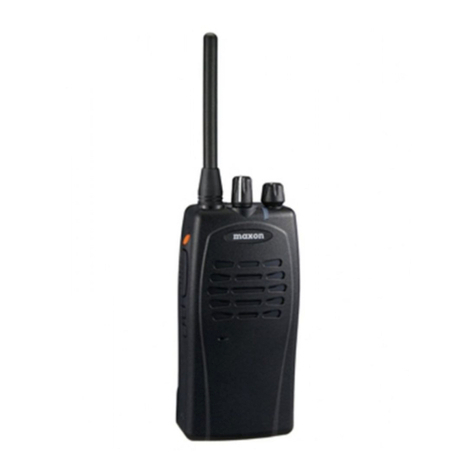
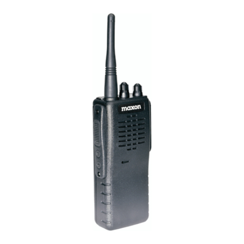
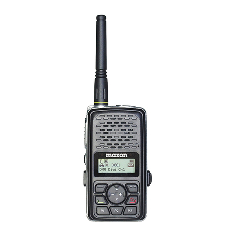
Maxon TPD-8000 Series User manual

Printed in Korea
Rev.201702A
11535 W. 83rd Terrace, Lenexa, KS 66214
Toll-Free: 800-456-2071 (US Only), 913-859-9515
Website: www.maxonamerica.com

11535 W. 83rd Terrace, Lenexa, KS 66214
www.maxonamerica.com
TPD-8000 Series
TPD-8124 (VHF)
TPD-8424 (UHF)
User Manual
EXPERIENCE
A NEW BEGINNING


www.tecnetusa.com
3
4
6
6
7
8
9
10
10
10
11
11
12
13
13
18
19
Table of Contents
Before operating the radio, please read the User Manual carefully.
The functions and specifications in the User Manual are subject to change without
notice for improvement of the radios performance.
1. Features
2. Specifications
3. Controls & LCD Display
Controls
Package Contents
Button and LED Operations
LCD Display Icons
4. Installation and Removal
Antenna Installation and Removal
Battery Installation and Removal
Belt Clip Installation and Removal
External Audio Accessory Jack
5. Charging the Battery
6. Radio Operation
MENU Functions
7. For Safe Operation
8. Warranty Statement
www.tecnetusa.com
2
www.maxonamerica.com

1. Features
The TPD-8000 Digital Radio was developed with the user in mind to provide a compact
and rugged design with features to fit multiple types of jobs. The following are the main
features of the TPD-8000 Series.
Digital (Tier II - TDMA) or Analog Mode
512 Channel Capacity; 16 Zones with 32 Channels per zone (1 zone = Max 32 Channels)
Mixed Channel Operation; Analog reception in Digital mode
RF Power Output - Maximum 3 watts
Choice of Case Color - Black, Blue, or Orange
High Capacity 2,200 mAh Li-Ion Battery
Text Messaging with Inbox and Outbox. Up to 10 Predefined Messages.
Secure Communications - Encryption mode 16 bit
USB Charge through Desk Top Charger or Direct through Radio
Lone Worker Mode
Multiple Scan Modes
VOX (Voice Operated Transmit)
Busy Channel Lock (BCL) / Busy Channel Lock Override (BCLO)
Time-Out Timer (TOT)
Emergency / Siren
Built in Flash Lamp
Etiquette (Vibration) function
Voice recording and playback
Six Squelch Levels (Analog mode)
Remote Radio Stun / Revive
1 Watt Audio Output
Locking Audio Accessory Connector
3 Lines Mono LCD Display (Numeric or Alphanumeric)
Die Cast Aluminum Frame
3

www.maxonamerica.com
4
2. Specifications
TPD-8124 (VHF)
Frequency Range
Frequency Stability
Programmable Channels
Channel Spacing
Digital Protocol
Dimensions (H/ W/D)
Weight (with Battery)
Operating Voltage/Power Source
Current Drain (maximum)
136~174 MHz
±1.0 ppm (-30 to +60°C)
512; 16 Zones with 32 Channels per Zone
25/20/12.5 kHz (Analog); 12.5 kHz/2 Time Slots 6.25 kHz (Digital)
Tier II (ETSI TS 102 361)
3.89 x 2 x .82 (99mm x 51mm x 21mm)
5.86 oz. (160g)
DC +3.7V; 2,200 mAh Li-Ion Battery
Receive mode, rated audio out - 320 mA (Audio Max)
Transmit mode - 1,800mA
Standby mode - 100mA
General
Sensitivity
Squelch Sensitivity
Selectivity
Spurious and Harmonic Rejection
FM Hum and Noise
Audio Output Power
Audio Distortion
Audio Response
0.25μV 12 dB (BER 1%)
0.22μV 10dB SINAD
>65dB (12.5KHz); 70dB (20/25 kHz)
70dB
40dB (12.5KHz)
1 Watt 8-ohm load
<3% at rated output
+1, -3 dB from 6dB per octave de-emphasis characteristic
from 300~3000Hz
Receiver
RF Power Output
Spurious and Harmonic
FM Hum and Noise
Audio Distortion
Audio Frequency Response
Digital Vocoder
3 Watt; 2 Watt Analog
70dB
40dB (12.5KHz)
3% maximum with 1KHz modulation
+1, -3dB from 6dB per octave pre-emphasis Characteristic
from 300 ~ 3000Hz
AMBE3000 with AMBE+2 Voice Compression Algorithm
Transmitter

5
TPD-8424 (UHF)
Frequency Ranges
Frequency Stability
Programmable Channels
Channel Spacing
Digital Protocol
Dimensions (H/ W/D)
Weight (with Battery)
Operating Voltage/Power Source
Current Drain (maximum)
380~420 MHz; 410~450 MHz; 440~470 MHz
± 1.0 ppm (-30 to +60°C)
512; 16 Zones with 32 Channels per Zone
25/20/12.5 kHz (Analog); 12.5 kHz/2 Time Slots 6.25 kHz (Digital)
Tier II (ETSI TS 102 361)
3.89 x 2 x .82 (99mm x 51mm x 21mm)
5.86 oz. (160g)
DC +3.7V; 2,200 mAh Li-Ion Battery
Receive mode, rated audio out - 320 mA (Audio Max)
Transmit mode - 1,800mA
Standby mode - 100mA
General
Sensitivity
Squelch Sensitivity
Selectivity
Spurious and Harmonic Rejection
FM Hum and Noise
Audio Output Power
Audio Distortion
Audio Response
0.25μV 12 dB (BER 1%)
0.22μV 10dB SINAD
>65dB (12.5KHz); 70dB (20/ 25 kHz)
70dB
40dB (12.5KHz)
1 Watt 8-ohm load
<3 % at rated output
+1, -3 dB from 6dB per octave de-emphasis characteristic
from 300~3000Hz
Receiver
RF Power Output
Spurious and Harmonic
FM Hum and Noise
Audio Distortion
Audio Frequency Response
Digital Vocoder
3 Watt; 2 Watt Analog
70dB
40dB (12.5KHz)
3% maximum with 1KHz modulation
+1, -3dB from 6dB per octave pre-emphasis Characteristic
from 300 ~ 3000Hz
AMBE3000 with AMBE+2 Voice Compression Algorithm
Transmitter

6
www.maxonamerica.com
3. Controls & LCD Display
Controls
ANTENNA
PROGRAMABLE BUTTONS
FLASH LAMP
EAR/ MIC JACK
TX/RX
STATUS LED
RETURN
BUTTON
POWER ON/OFF
BUTTON
VOLUME / SELECTION
CHARGE LED
PROGRAMABLE
BUTTON
USB DATA/ CHARGER CONNECTOR
+ TERMINAL - TERMINAL ANTENNA CONNECTOR
EAR/ MIC JACK
PTT BUTTON
MENU/ENTER
BUTTON
CONTACT
BUTTON

7
Package Contents
Radio
Battery Desk Top Charger Adapter & USB cable
Antenna Basic / Optional
Belt clip
User Manual

8
Power ON/OFF
Press and hold the power button for 3 seconds to power ON. Press and hold
the power button for 3 seconds during use to power OFF. When powered ON
short press returns to main screen.
Volume Button +/-
Press +/- to either increase or decrease the volume. If in the menu screen, it
moves through different functions (Left & Right).
Channel Button
Press to change channel. If in the menu screen, it moves through
different functions (Up & Down).
Menu/ Enter Button
Press to enter the Menu. Additional presses indicate functions to choose from
in the menu.
Return Button
Press the button to return to previous item in menu. Additional presses keep
returning to previous menu item.
Contact Button
Press the button to enter the contact list programmed into the radio.
Press the to move through the list of contacts.
P1, P2, P3 Button
Press of the buttons allow the enable and disable of programmed functions.
Optional short press and long press are available. Default long press of each
button is as follows:
- P1 is to enable or disable the lock function.
- P2 is to turn Flash Lamp On / Off
- P3 is to turn Etiquette (Vibrate) On / Off
PTT Button
Press PTT to place radio into transmission mode and release for receive
mode. It is recommended to hold the radio 2 to 4 away while speaking into
the microphone. TX/ RX Status LED will illuminate RED when transmitting and
GREEN when receiving.
TX/ RX Status / Low
Battery LED
TX/RX Status LED will illuminate RED when transmitting and GREEN when
receiving. If the LED blinks GREEN, the frequency is the same but the color
code does not match.
Low Battery: LED blinks RED with beep sound.
Button & LED Operation Description
Button & LED Operations
www.maxonamerica.com
9
LCD Display Icons
Numeric display
Alpha numeric display (Message)
Received signal strength
Encryption mode
VOX
RF Output
D : Digital
A : Analog
DM : Direct Mode
RM : Repeater Mode
Zone Number
Battery Capacity Display
Etiquette Mode (Vibration mode)
Scan Mode
Zone Display
Zone
Zone NO
Channel NO
Alphanumeric
Display
Channel Display
Message Reception
Button Locking

10
4. Installation and Removal
Antenna Installation and Removal
To install the antenna, insert the antenna into antenna
connector and screw the antenna clockwise.
To remove the antenna, screw the antenna counter
clockwise.
Battery Installation and Removal
Remove the back cover using the slot located at the top of the cover to separate from the frame as
shown in Figure 1.
Removal of the battery is accomplished by pushing up the battery and then removing at the bottom.
Installation is accomplished by inserting the top of the battery in and then placing the bottom into the
radio as shown in Figure 2.
Install the back cover by inserting the tabs into the bottom of the frame and compress from the bottom
to the top until the case snaps completely into place. See Figure 3.
1. Do not over tighten the antenna as it may cause
damage to the radio.
2. NEVER HOLD by the antenna when carrying
the transceiver.
3. Transmitting without an antenna may damage
the transceiver.
Figure 1: Back cover removal
Figure 2: Battery installation and removal Figure 3: Rear cover installation
PUSH
PUSH
PUSH
UP
DOWN
DOWN
www.maxonamerica.com
11
Belt Clip Installation and Removal
Align the belt clip with the designated side slot and screw hole in frame. Tighten the screw as shown
in Figure 4. Conversely, loosen the screw to remove the belt clip.
External Audio Accessory Jack
Open the accessory cover and align the accessory connector with the accessory jack. Push down
and turn clockwise to lock the accessory into the jack.
To remove the accessory, push down and turn counter clockwise: See Figure 5.
Figure 5: External accessory connection
Figure 4: Belt clip installation and removal
Align the body with accessory hole
PUSH
TURN

12
Charge the battery before initial use of the radio for best performance.
IMPORTANT - If charging the battery while it is installed on the radio, it is recommended to
turn off the radio. However, the battery will charge while the radio is on.
Figure 6: Charging USB direct into radio Figure 7: Charging with Desktop Charger
The use or charging of a battery other than the factory designated battery may cause
damage and void the warranty to the battery, charger, and/or radio.
5. Charging the Battery
Charging Direct into Radio - Open the flap to expose the USB Data/Charging Connector located on
the bottom of the radio and connect the micro USB charging adaptor. See Figure 6. Connect the
USB into a PC or applicable USB converter.
Charging with Desktop Charger - Inset the micro USB into the charger base. See Figure 7.
Insert the radio into the charger base. Connect the USB into a PC or applicable USB converter.
The charger LED located on the face of the radio will illuminate RED indicating the unit is charging.
When charging is completed, the LED will illuminate GREEN.
www.maxonamerica.com
13
Certain settings for the eight (8) functions from the menu are enabled and disabled through the
programming of the radio via the Programming Software (PS). Contact your Authorized Dealer for
information.
Note - If the menu is not operated for at least 25 seconds after launch, the radio will revert to
standby mode.
Figure 8: TPD-8000 Series Menu Tree
Contact
Contact
Individual call
Group Call
All Call
Messages
Quick Text
Inbox
Outbox
Call Logs
Incoming
Outgoing
TPD-8000 Radio Main Menu
Scan
Scan On/Off
Scan List
Zone Setting
Power Level
Encryption
VOX
Lone Walker
BCL/BCLO
Keypad Lock
Tones
Radio Info
Radio ID
Model Name
PBC Version
Freq Range
SW Version
BB Number
BB Version
Last update
Made Date
Messages Call Logs Record Scan Zone Setting Radio Info
Voice Record
Record ON/OFF
Record List
Backlight
Brightness
LED Control
Language
Screen
Power Save
6. Radio Operation
MENU Functions
To enter the menu tree as displayed in Figure 8, press the menu/enter button. Press the Volume - /
Left button or Volume + / Right button to move to the desired menu selection. All functions are
available in Digital Mode. In Analog Mode, the functions available are Scan, Zone, Setting, and
Radio Info.

14
www.maxonamerica.com
1.
Contact List (Digital Mode Only)
The Contact List provides a list of individuals, groups or all calls of which you can make a direct
call. The lists of contacts are set within the radio by the PS. To initiate a call, select the Contacts
section from the menu (or press the contact button for direct access), press the menu/enter
button to see the list of contacts, press the keys to the desired contact and press the PTT
button to initiate the call. The radio will revert to the original contact/channel after a preset time
as set by the PS. When you enter in the contact menu, the applicable icon will be shown
indicating the type of call.
ICON
- : Individual Contact List
- : Group Contact List
- : All Contact List
2. Messages (Digital Mode only)
The Message section offers the ability to perform one of the three functions.
Quick Text - The ability to send from a choice of 10 preset messages with up to 40 characters per
message. The preset messages are set by the PS.
Inbox - Stores up to 10 received text messages; when the received messages exceed 10, the
oldset message is cleared and the newest incoming message is registered. When a new
message arrives, the contents will be displayed on the LCD screen. When you choose messages
stored in the list, you can view the received messages and the caller ID that initiated the call.
Outbox - Stores up to 10 outgoing text messages; when the outgoing messages exceed 10, the
oldset message is cleared and the newest sent message is registered. When you choose
messages stored in the list, you can view the sent messages and the caller ID to whom they
were sent.
To obtain access, select the Messages section from the menu, press the menu/enter button to
enter into Messages and use the keys to highlight one of the three choices:
a) Quick Text
Select Quick Text from the message menu by pressing the menu/enter button to view the
registered message(s).
Using the keys, select the message you want to send, and press the menu/enter button
to see the contents of the message. Press the menu/enter button again to view the list of
contacts, and using the keys, select the contact for the message to be sent. Press the
menu/enter button and the message will be sent to the contact(s). An acknowledgement will
be shown on the display of either “Sent Success” or “Sent Fail”. If the message is failed, check
to make sure that the user receiving the message has their unit powered on.

15
b) Inbox
Text messages are shown initially on the screen. If you are in another mode or miss the
message, the message icon will be displayed indicating a new message(s) has arrived.
Select inbox from the message menu by pressing the menu/enter button to view the
registered message(s). Using the keys, select the message you want to view, and press
the menu/enter button to see the contents of the messages. Messages that have yet to be
viewed will be indicated with a downward arrow inside the envelope; after a message is
viewed the arrow will no longer be shown.
If you want to delete messages from the Inbox, select #2 Delete All from within the Inbox
menu by pressing the menu/enter button, the question to Delete All will appear with the word
“Yes?” Press the menu/enter button to delete all messages. If you choose not to delete the
messages, press the return button to exit out.
c) Outbox
Select Outbox from the message menu by pressing the menu/enter button to view the
outgoing message(s). Using the keys, select the message you want to view. At this
point, you can resend the message. Press the menu/enter button to view the contents of the
message. Using the keys, select the message you want to send, and press the menu
/enter button to see the contents of the message. Press the menu/enter button again to view
the list of contacts, and using the keys, select the contact for the message to be sent.
Press the menu/enter button and the message will be sent to the contact(s). An
acknowledgement will be shown on the display of either “Sent Success” or “Sent Fail”. If the
message is failed, check to make sure that the user receiving the message has their unit
powered on.
To delete messages from the Outbox, select #2 Delete All from within the Outbox menu by
pressing the menu/enter button, the question to Delete All will appear with the word
“Yes?” Press the menu/enter button to delete all messages. If you choose not to delete the
messages, press the return button to exit out.
Note - When sending and receiving text messages, turn off the power saving mode.
3. Call Logs (Digital Mode Only)
The function allows the viewing of incoming and outgoing calls from individuals only. The call log
contents are managed in the same manner as in the inbox/outbox of the messages section
(reference #2 Messages).
4. Call Recording (Digital Mode Only)
This function is used to record the content of outgoing and incoming calls in digital mode only.
There are 3 choices of Settings, Lists, and Delete All. Up to 63 conversations/recordings can be
stored with each recording limited to 150 seconds. When the recordings exceed 63, the oldest
message is cleared and the newest incoming message is registered.
Settings - This section allows the capability to turn the recording capability on or off.

16
Lists - This section allows the viewing of the recorded messages and to play back each
message. To play back a message, use the keys to the desired message and press the
menu/enter button to play the recording.
Delete All - This function provides the capability to delete stored recordings. To delete recordings,
select Delete All from within the Voice Recording menu by pressing the menu/enter button, the
question to Delete All will appear with the word “Yes?” Press the menu/enter button to delete all
recordings. If you choose not to delete the recordings, press the return button to exit out.
5. Scan
This function provides the ability to turn scan on/off and review the scan list as programmed into
the radio via the PS. The ability to scan digital and analog channels are available. Contact your
Authorized Dealer for further information.
6. Zone
Up to 16 zones (with up to 32 channels per zone) can be programmed into the radio via the PS.
To select the desired zone, press the keys and press the menu/enter button to accept the
zone. Contact your Authorized Dealer for further information.
7. Settings
This function allows the change to the settings of Power Level, Squelch Level, Voice Operated
Transmit (VOX). Lone Worker, Busy Channel Lock (BCL)/ Busy Channel Lock Out (BCLO).
Keypad Lock, Tones, Backlight, Brightness, LED Control, Language, Screen, and
Power Save.
a. Power Level
This function sets the power transmitting level at high or low. The setting of low power improves
battery life, but diminishes talk range.
b. Squelch Level (Analog Only)
This function allows the ability to change the squelch levels of Open,1,2,3,4, or Tight.
c. VOX
VOX function allows transmitting without using the PTT button.
VOX sensitivity level is adjusted from 1 to 5 with 5 being the most sensitive.
d. Lone Worker (Digital Mode Only)
This function can inform others about your safety within the time set in the menu. Contact your
Authorized Dealer for further information.
e. BCL/BCLO
This function prevents interference when the channel is busy.
-Digital Mode Only
BCL On: If the current channel is busy, the transmission is prohibited.
www.maxonamerica.com
17
- Analog Mode
BCL On & BCLO Off: If the current channel is busy, transmitting is prohibited.
BCL On & BCLO On: Transmitting occurs when it matches the received tone.
f. Keypad Lock
This function locks the keypad to prohibit the accidental press of keys and buttons.
When the keypad lock is enabled, all keys/buttons are locked except the PTT button, the
emergency button, and power ON / OFF button. If any of these buttons are pushed, the
keypad lock will enable again after 25 seconds from the pressing of the last button.
Press the key for 2 seconds to temporarily unlock the keypad for 25 seconds.
g. Tones
This function enables or disables the tones associated with key and button presses.
Additional tone settings can be set via the PS. Contact your Authorized Dealer for futher
information.
h. Backlight
This function allows the backlight of the LCD to be turned ON/OFF and timed. The duration
for the timed section is set via the PS. Contact your Authorized Dealer for futher information.
i. Brightness
This function is to adjust the contrast /brightness of the LCD from low to high.
j. LED Control
This function is to set the enable or disable the radio status LED. The LED status can be
set via the PS.
k. Language
This function is to select the language (English or Korean) for the menus.
l. Screen Setting
This function allows the ability to change between Screen 1 for Numeric or Screen 2 for
Alphanumeric. The information displayed is set via the PS. Contact your Authorized Dealer
for futher information.
m. Power Saving Mode
This function allows the radio to enter a power saving mode to extend battery usage time.
Off is full power, 1/1 is 50% on/50% off; 1/2 is 33% on/67% off; 1/4 is 25% on/75% off.
Note: When sending and receiving text messages, turn off the power saving mode.
Additional features that can only be set and initiated through the PS.
Voice Encryption (Digital Mode Only)
This is a feature to encrypt the incoming and outgoing voice. Voice Encryption function can only
be performed through digital channels. The setting of voice encryption codes is set via the PS.
Contact your Authorized Dealer for futher information.

18
www.maxonamerica.com
7. For Safe Operation
•
FCC RF EXPOSURE COMPLIANCE REQUIREMENTS FOR OCCUPATIONAL USE ONLY
The Federal Communications Commission (FCC), with its action in General Docket 93-62, November 7, 1997, has
adopted a safety standard for human exposure to Radio Frequency (RF) electromagnetic energy emitted by FCC
regulated equipment. Proper operation of this radio will result in user exposure far below the Occupational Safety and
Health Act (OSHA) and Federal Communications Commission limits.
•
DO NOT
transmit for more than 50% of total radio use time (50% duty cycle). Transmitting more than 50% of the
time can cause FCC RF exposure compliance requirements to be exceeded.
•
This radio is NOT approved for use by the general population in an uncontrolled environment. This radio is restricted
to occupational use, work related operations only where radio operator must have the knowledge to control the user’s
exposure conditions for satisfying the higher exposure limit allowed for occupational use.
•
When transmitting, hold the radio in a vertical position with its microphone 1 inches (2.5 cm) away from your mouth.
•
The radio is transmitting when the red LED on the front of the radio is illuminated. You can cause the radio to transmit
by pressing the PTT bar on the radio.
•
These are required operating configurations for meeting FCC RF exposure compliance. Failure to observe these
restrictions mean violation.
This device complies with part 15, 90 of the FCC rules. Operation is subject to the following two conditions: (1) This
devices may not cause harmful interference, and (2) This device must accept any interference received, including
interference that may cause undesired operation.
FCC Notice
This manual suits for next models
2
Table of contents
Other Maxon Two-way Radio manuals

Maxon
Maxon PM100 User manual

Maxon
Maxon FRS-114 User manual

Maxon
Maxon TK14-VWX User manual

Maxon
Maxon TSD-4000 Series User manual

Maxon
Maxon SM-4450 User manual

Maxon
Maxon TPD-8124 User manual

Maxon
Maxon S5 PMR446 User manual

Maxon
Maxon FRS-214 User manual

Maxon
Maxon CM10 User manual

Maxon
Maxon SP-200K Series User manual

Maxon
Maxon FRS-100 User manual

Maxon
Maxon SP-200 Series User manual

Maxon
Maxon SP-300 Series User manual

Maxon
Maxon S5E PMR446 User manual

Maxon
Maxon SP-1402 User manual

Maxon
Maxon TP-8000 User manual

Maxon
Maxon SP-100 User manual

Maxon
Maxon GMRS-21X User manual

Maxon
Maxon SL-7402 Parts list manual

Maxon
Maxon GMRS-50 User manual