manuals.online logo
Brands
  1. Home
  2. •
  3. Brands
  4. •
  5. Mayline
  6. •
  7. Indoor Furnishing
  8. •
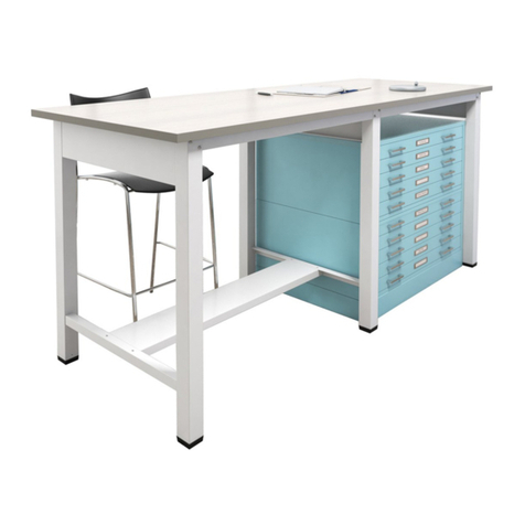
  9. Mayline 50/50 Split Top Ranger Table 7774 User manual

Mayline 50/50 Split Top Ranger Table 7774 User manual

MODELS:
7774..........LPL SURFACE
7774L........HPL SURFACE
7774A........LPL SURFACE / TOOL DRAWER
7774LA......HPL SURFACE / TOOL DRAWER
7774B........LPL SURFACE / TOOL & REF.DRAWERS
7774LB......HPL SURFACE / TOOL & REF. DRAWERS
R
1
50/50 Split Top R nger T ble
T ble of Contents.......................................................p ge 1
Tools nd S fety........................................................p ge 2
Exploded View with B.O.M (T ble).............................p ge 3
Exploded View with B.O.M (Option l Dr wers)..........p ge 4
H rdw re B.O.M........................................................ p ge 5 & 6
Assembly Instructions (T ble)....................................p ge 7-9
Assembly Instructions (Option l Dr wers).................p ge 10-13
Assembly Instructions (Tilt Top & Reference Top).....p ge 14
Inst ll tion (Tilt Top, Dust Cover, Reference Top).....p ge 15
I922 9-16 REV. 2
7774 & 7774L
7774A & 7774LA 7774B & 7774LB
TOOLS REQUIRED
POWER DRIVER
WITH #2 PHILLIPS BIT
#2 PHILLIPS SCREWDRIVER
7/16" WRENCH
3/8" WRENCH
SAFETY TIPS
INSTALLATION REQUIRES A
MINIMUM OF 2 PEOPLE
WHENEVER POSSIBLE, ASSEMBLE
PRODUCT AT OR NEAR ITS FINAL
LOCATION.
ALWAYS WEAR EYE PROTECTION
IMPORTANT!
Review ALL instructions before
beginning assemb y. These
instructions re provided to void
problems th t m y occur from
improper ssembly or inst ll tion.
M yline nd/or its distributor re not
responsible for f ilure resulting from
improper ssembly or inst ll tion of
this product. Moreover, ll
w rr nties re void for f ilure to
follow these ssembly instructions.
2
50/50 Split Top R nger T ble
1 1
ITEM QTY
2 1
3 1
4 1
5 1
6 1
7 1
8 1
9 2
END ASSEMBLY, L.H. 29.62 X 34.97
DESCRIPTION
RAIL, SPLIT 50/50 FRONT 55.19
FOOT RAIL
DUST COVER 28.35 X 28.87
RANGER, SPLIT 50/50 TILT
NOTE: DIMENSIONS LISTED ARE NOMINAL
1
2 5
6
7
9 10
END ASSEMBLY, R.H. 29.62 X 34.97
8
10 1
3
4
BACK RAIL 50/50 SPLIT TOP 55.19
RANGER, SPLIT 50/50 SIDE REF.
RAIL, SUPPORT
FRAME WELD, 50/50 RANGER
PART No.
A7917
A7918
B9600
B2026
B9599
12977
12976
L89319
B6543
A9248
11
11 1 PANEL, DRAWER COVER B9643
3
50/50 Split Top R nger T ble
12 4 PLASTIC FOOT F950
12
12
16
2/4
ITEM QTY
12
113
114
115
1
PROGRESSIVE SLIDE
DESCRIPTION
PLASTIC TRAY, 4 POST
DRAWER, TOOL WELD ASM
DRAWER, REFERENCE WELD ASM
SUPPORT, CENTER
PART No.
B6361
A7655
B7469
A7553
F187
12
13
14
15
12
16
"OPTIONAL" Dr wer Components
4
50/50 Split Top R nger T ble
KEPS Nut
#10-24
T2
KEPS Nut
1/4-28
T25
14
M
15L
K
J
H
18
5
15
PPHTC
#10-32 x 1/2"
PFHTC
#10-32 x 1/2"
PRHMS
#1/4-28 x 3/8"
X204
X191
X156
N me P rt Qty.
11
F
PTHSMS #8 x 5/8"
X140A
1E
Joining Pl te
B7522
Lift Assembly
V120A
2
D
Glide
X453
4
C
Lower Hinge
Upper Hinge
B194
B195
2
B
A
N me P rt Qty.
2
50/50 Split Top R nger T ble
5
H rdw re B g Contents - BASE (A9249):
G14
PTHMS
#10-24 x 3/8"
X147
P n He d Screw
#10 x 3/4 "
X11
18N
Rubber
Bumper
D10
2
P
50/50 Split Top R nger T ble
6
V
Pencil Stop
Lock
Q52
1
1
U
N me P rt Qty.
PPHMS
#8-32 x 5/16"
X384
Acorn Nut
#8-32
T129
R
Q
N me P rt
13
Qty.
13
PPHTC
#8-32 x 3/8"
X247
T
S
H ndle
Q35
1
9
2
P n He d Screw
#10 x 3/4 "
X11
X4
Nylon W sher
992102
B9718
H rdw re B g Contents -
OPTIONAL Dr wers:
Pencil Stop
Repl cement P rts
'FLIP'
for ssembly
Di gon l holes
'DOWN'
Di gon l holes
'DOWN'
NOTE: These di gon l holes indic te
front of the 'H' fr me.
10
K
7/8"
1"
7
50/50 Split Top R nger T ble
1. Position the 'H' Fr me (10) with the di gon l holes
tow rd the FRONT AND DOWN. Position e ch
Support Ch nnel (9) with the 7/8" notch tow rd the
front. Att ch the Support Ch nnels (9) to the 'H'
Fr me (10) using #10-32 x 1/2 Screws (K) through
the lower set of slots.
Position the Dr wer P nel Cover (11) with the offset
"DOWN" nd tow rd the front. Position the fl nge
"UP" nd tow rd the re r. Att ch the cover using 6
screws (K).
X204
PPHTC
#10-32 x 1/2"
12
K
10 9 9
11
9
K
7/8"
For t bles without Option l Dr wers -
continue ssembly on p ge 13 with Tilt
Top nd Reference Top ssembly
NOTE:
This hole
tow rd re r
M G
L H
L H L H
C
4
5
2
3
GLIDE
X453
4C
G8
PTHMS
#10-24 x 3/8"
X147
8
KEPS NUT
#10-24
T2
M
H14
PRHMS
#1/4-28 x 3/8"
X156
KEPS NUT
1/4-28
T25
14L
NOTE:
Inside screw/nut
loc tion Re r R il to
Re r Legs
NOTE: For e se of ssembly, ssemble B se 'UPSIDE DOWN'.
2. Pl ce the two End Assemblies (1 & 2) upside down with the side p nel hole tow rd the re r. Position the
Front R il (5) with notches 'UP'. Position the Re r R il (3) with the tt chment holes 'DOWN'. Position 'H'
fr me ssembly (Step 1) with dr wer cover p nel 'UP' nd 7/8" ch nnel notch tow rd 'FRONT'.
3. Secure the 'H' Fr me/Support Assembly from step 1 to the Front nd Re r R ils (3&5) using #10-24 x
3/8 Screw (G) nd KEPS Nuts (M). DO NOT tighten screws t this time.
4. Secure the Front R il (5) to the End Assemblies (1&2) with two Screws (H) nd two Nuts (L) per end.
Secure the Re r R il (3) to the End Assemblies (1&2) with three Screws (H) nd three Nuts (L) per end.
Note inside Screw & Nut loc tion for re r legs. DO NOT tighten screws t this time.
5. Position the Foot R il (4) with fl t surf ce 'DOWN'. Att ch the Foot R il (4) to the End Assemblies (1&2)
with four Screws (H) nd Nuts (L).
6. TIGHTEN ALL r il tt ching screws now.
7. Inst ll Glides (C) into the End Assemblies.
8. Turn ssembled t ble to n upright position.
MAYLINE recommends th t two people perform this t sk.
50/50 Split Top R nger T ble
8
L
H
L H
R il
Notches
Cover
P nel
1
9. Att ch Lower Hinges (B) to 'H' fr me with
#10-32 x 1/2 Thre d Cutting Screw (S).
Position with hinge slot tow rd front of t ble.
B2
B195
LOWER HINGE
K 4
For t bles without Option l Dr wers -
continue ssembly on p ge 14 with Tilt
Top nd Reference Top ssembly
9
50/50 Split Top R nger T ble
K B
X204
PPHTC
#10-32 x 1/2"
14 14
"OPTIONAL" Dr wer Assembly
10. Sep r te the Dr wer Slides (12) into two pieces (12A & 12B).
Extend the Slide to the full extension. Remove the sm ller portion
(12B) by pressing the pl stic rele se nd pulling.
11. Att ch the l rge Slide portion (12A) to the Center Support (13)
using two Screws (S). Begin tt ching the Slide portion (12A)
using the l rge 'Horizont l' slot in the l st slide mounting t b.
NOTE: When ssembling the Reference Dr wer, repe t step #2
on the opposite side of the Center Support.
REFERENCE
DRAWER SLIDE
TOOL
DRAWER SLIDE
Begin
"HERE"
"PRESS"
PULL
S4
X247
PPHTC
#8-32 x 3/8"
12
12A 12B
12A
Begin
"HERE"
12A
S
S
10
50/50 Split Top R nger T ble
1
2
"OPTIONAL" Dr wer Assembly
Begin "HERE" Begin "HERE"
12. Att ch one l rge Slide portion (12A) to the br ckets on the
End Assemblies (1 & 2) using two Screws (S). Using the
LOWER set of holes for Tool Dr wer inst ll tion (R.H. Side),
begin tt ching the Slide using the l rge 'Horizont l' slot in the
l st mounting t b.
When inst lling the Reference Dr wer, repe t this procedure on
the L.H. Side Assembly using the UPPER set of holes.
S4
X247
PPHTC
#8-32 x 3/8"
L.H. Side - Reference Dr wer R.H. Side - Tool Dr wer
12A 12A
S S
11
50/50 Split Top R nger T ble
"OPTIONAL" Dr wer Assembly
Begin "HERE"
Begin "HERE"
13. Att ch the sm ller Slide portion (12B) to e ch side
of the Tool Dr wer (15) using three Screws (Q) nd
three Acorn Nuts (R). Begin tt ching the Slide using
the 'Vertic l' slot in the first hole cluster.
NOTE: When ssembling the Reference Dr wer (13),
repe t Step 13, beginning t the s me vertic l slot in
Slide portion 12B s on the tool dr wer ssembly.
14. Inst ll the Dr wer Pull (T) onto the Tool Dr wer
he d using Screws (G).
12
Q
R12
T129
ACORN NUT
#8-32
X384
PPHMS
#8-32 x 5/16"
Q35
HANDLE
T 1
U 1
Q52
LOCK
6G
X147
PTHMS
#10-24 x 3/8"
T
12B
R Q
G
R Q
12B
U
15
13
12
50/50 Split Top R nger T ble
13
14
G M
G M
G4
PTHMS
#10-24 x 3/8"
X147
4
KEPS NUT
#10-24
T2
M
15. Inst ll the ssembled Center Support (14) into the B se.
Att ch the Support with two Screws (F) nd two Nuts (M) per
front nd re r r il.
"OPTIONAL" Dr wer Assembly
16. Att ch the Upper Hinges (A)
to the underside of the Tilt Top
(7) with #10 x 3/4 P rticle Bo rd
Screws (N). Position with the
hinge t b tow rd the front edge
of the top.
17. Att ch the Joining Pl te
(E) to the underside of the
Side Reference Top (6)
with #10 x 3/4 P rticle
Bo rd Screws (N).
Underside
(Tilt Top)
Underside
(Side Ref.)
2
A
B194
UPPER HINGE
N 6
X11
PAN HEAD SCREW
#10 x 3/4 "
B7522
JOINING PLATE
N 4
X11
PAN HEAD SCREW
#10 x 3/4 "
A N 7
E 1
E N
6
14
50/50 Split Top R nger T ble
D 2
V120A
LIFT ASSEMBLY
X140A
PTHSMS #8 x 5/8"
F10
X191
PFHTC
#10-32 x 1/2"
4
J
N 6
P2
X11
PAN HEAD SCREW
#10 x 3/4 "
D10
RUBBER
BUMPER
15
5"
4"
18"
6
N
D
J
7
N
F N P
8
19. Att ch Lift Assembly (D) to the 'H' Fr me
cross r il with #10-32 x 1/2 Fl t He d Screws (J).
20. Inst ll the Tilt Top (7) onto the t ble. R ise
the Lift Assembly nd lign the holes in the lift
with the holes in the top. Att ch with #10 x 3/4
P rticle Bo rd Screws (N).
21. Att ch the Reference Top (6) to the b se with
#10 x 3/4 P rticle Bo rd Screws (N) through the
front nd re r r il nd through the side r il
fl nge.
22. Att ch Dust Cover (8) to b se with #8 x 5/8
Screws (F).
23. Att ch Top Bumpers (P) to Dust Cover with
#10 x 3/4 Screw (N). Position pproxim tely s
shown. Me sured from edges of dust cover.
24. Inst ll ssembled Tool nd Reference
dr wers into t ble if so equipped.
50/50 Split Top R nger T ble
R
I922 9-16 REV.2

This manual suits for next models

5

Other Mayline Indoor Furnishing manuals
Mayline Sterling STEDSF72 User manual

Mayline

Mayline Sterling STEDSF72 User manual

Mayline Sterling Series User manual

Mayline

Mayline Sterling Series User manual

Mayline realoffice Aberdeen ARDTC User manual

Mayline

Mayline realoffice Aberdeen ARDTC User manual

Mayline Sterling STEB2C User manual

Mayline

Mayline Sterling STEB2C User manual

Mayline 1001VTL User manual

Mayline

Mayline 1001VTL User manual

Mayline Medina Series User manual

Mayline

Mayline Medina Series User manual
Mayline CSII P Table User manual

Mayline

Mayline CSII P Table User manual

Mayline CSII OPEN SHELF OVERHEAD User manual

Mayline

Mayline CSII OPEN SHELF OVERHEAD User manual

Mayline Medina Series User manual

Mayline

Mayline Medina Series User manual

Mayline XR User manual

Mayline

Mayline XR User manual

Mayline MANAGERIAL MID-BACK CHAIR User manual

Mayline

Mayline MANAGERIAL MID-BACK CHAIR User manual

Mayline 1006 User manual

Mayline

Mayline 1006 User manual

Mayline Sterling Series User manual

Mayline

Mayline Sterling Series User manual

Mayline Sterling Series User manual

Mayline

Mayline Sterling Series User manual

Mayline e*LAN 24" WORKSTATIONS User manual

Mayline

Mayline e*LAN 24" WORKSTATIONS User manual

Mayline Medina Series User manual

Mayline

Mayline Medina Series User manual

Mayline CSII J User manual

Mayline

Mayline CSII J User manual

Mayline MAYTRIX LAN FURNITURE 90 DEGREES CORNER WORK... User manual

Mayline

Mayline MAYTRIX LAN FURNITURE 90 DEGREES CORNER WORK... User manual

Mayline CSII FREESTANDING PENINSULA C625 User manual

Mayline

Mayline CSII FREESTANDING PENINSULA C625 User manual

Mayline realoffice Brighton BTB4824 User manual

Mayline

Mayline realoffice Brighton BTB4824 User manual

Mayline DUAL XR BASE User manual

Mayline

Mayline DUAL XR BASE User manual

Mayline 1001VTG User manual

Mayline

Mayline 1001VTG User manual

Mayline A7680 User manual

Mayline

Mayline A7680 User manual

Mayline Aberdeen Series User manual

Mayline

Mayline Aberdeen Series User manual

Popular Indoor Furnishing manuals by other brands

Hartman RESIDENCE EXTENSION instructions

Hartman

Hartman RESIDENCE EXTENSION instructions

Cooper Lighting Portfolio 860 Specification sheet

Cooper Lighting

Cooper Lighting Portfolio 860 Specification sheet

John Lewis Morgan 803/16409 instructions

John Lewis

John Lewis Morgan 803/16409 instructions

Rockler 54102 instructions

Rockler

Rockler 54102 instructions

INSPIRE Q E817-04 Assembly instruction

INSPIRE Q

INSPIRE Q E817-04 Assembly instruction

Hailey Home AT1284 Assembly instructions

Hailey Home

Hailey Home AT1284 Assembly instructions

Knight Eko Credenza Assembly instructions

Knight

Knight Eko Credenza Assembly instructions

iCube SIDEBOARD LUXE instructions

iCube

iCube SIDEBOARD LUXE instructions

DISPLAY ONE Presentation Podium Assembly instructions

DISPLAY ONE

DISPLAY ONE Presentation Podium Assembly instructions

Kenroy Home SVEN 73003 Use and care guide

Kenroy Home

Kenroy Home SVEN 73003 Use and care guide

U-Line H-10142 quick start guide

U-Line

U-Line H-10142 quick start guide

Granberg Centerlift 6490 user manual

Granberg

Granberg Centerlift 6490 user manual

Ovela THEODORE OVTHEODRDGA user guide

Ovela

Ovela THEODORE OVTHEODRDGA user guide

Bechara CARTIER Center table Product Guide and Assembly Instructions

Bechara

Bechara CARTIER Center table Product Guide and Assembly Instructions

Made JONAH manual

Made

Made JONAH manual

Bestar 99810-1139 manual

Bestar

Bestar 99810-1139 manual

M4TEC SpacePro Assembly guide

M4TEC

M4TEC SpacePro Assembly guide

Whittier Wood Furniture John Greenleaf Savannah 372W Assembly instructions

Whittier Wood Furniture

Whittier Wood Furniture John Greenleaf Savannah 372W Assembly instructions

manuals.online logo
manuals.online logoBrands
  • About & Mission
  • Contact us
  • Privacy Policy
  • Terms and Conditions

Copyright 2025 Manuals.Online. All Rights Reserved.