manuals.online logo
Brands
  1. Home
  2. •
  3. Brands
  4. •
  5. Maytag
  6. •
  7. Air Conditioner
  8. •
  9. Maytag Amana DIRECT COMFORT DC-CSCF3642N6 User manual

Maytag Amana DIRECT COMFORT DC-CSCF3642N6 User manual

Important Safety Instructions
The following symbols and labels are used throughout this
manualtoindicateimmediateorpotentialsafetyhazards. Itis
the owner’s and installer’s responsibility to read and comply
withallsafetyinformationand instructionsaccompanyingthese
symbols. Failuretoheedsafetyinformationincreasestherisk
ofpersonalinjury,propertydamage,and/orproductdamage.
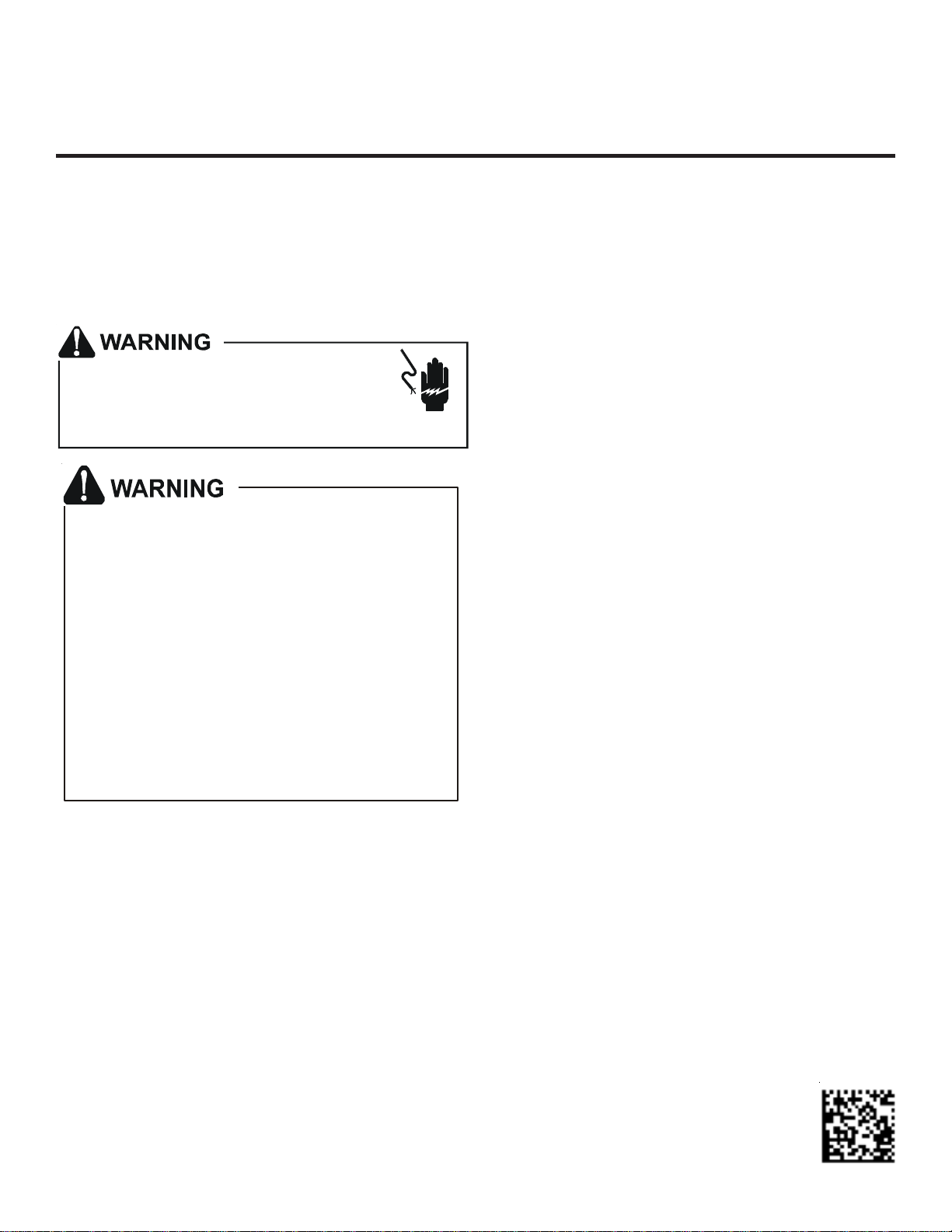
HIGH VOLTAGE!
Failure to do so may cause property
damage, personal injury or death.
Disconnect ALL power before servicing or
installing this unit. Multiple power sources
may be present.
Only personnel that have been trained to install,
adjust, service or repair (hereinafter, “service”) the
equipment specified in this manual should service
the equipment. The manufacturer will not be
responsible for any injury or property damage arising
from improper service or service procedures. If you
service this unit, you assume responsibility for any
injury or property damage which may result. In
addition, in jurisdictions that require one or more
licenses to service the equipment specified in this
manual, only licensed personnel should service the
equipment. Improper installation, adjustment,
servicing or repair of the equipment specified in this
manual, or attempting to install, adjust, service or
repair the equipment specified in this manual without
proper training may result in product damage,
property damage, personal injury or death.
Shipping Inspection
Upon receiving the product, inspect it for damage from ship-
ment. Shipping damage, and subsequent investigation is the
responsibilityofthe carrier. Verify the model number, specifi-
cations, electrical characteristics, and accessories are cor-
rectpriortoinstallation. The distributorormanufacturerwillnot
accept claims from dealers for transportation damage or in-
stallation of incorrectly shipped units.
HORIZONTALCOILS
INSTALLATION INSTRUCTIONS
Codes & Regulations
This product is designed and manufactured to comply with
nationalcodes.Installationinaccordancewith suchcodesand/
orprevailinglocalcodes/regulationsistheresponsibilityof the
installer. Themanufacturerassumesnoresponsibilityforequip-
mentinstalled in violation of anycodes or regulations.
TheUnited States EnvironmentalProtection Agency (EPA)
has issued various regulations regarding the introduc-
tion and disposal of refrigerants. Failure to follow these
regulations may harm the environment and can lead to
the imposition of substantial fines. Theseregulationsmay
vary by jurisdiction. A certified technician must perform the
installation and service of this product. Should you have any
questions please contact the local office of the EPA.
Replacement Parts
Whenreporting shortagesordamages,ororderingrepairparts,
givethecompleteproductmodelandserialnumbersasstamped
onthe product. Replacement parts for this product areavail-
able through your contractor or local distributor. For the loca-
tion of your nearest distributor consult the white business
pages,the yellow pagesection of the local telephone book or
contact: HOMEOWNERSUPPORT
GOODMANMANUFACTURINGCOMPANY,L.P.
19001KERMIERROAD
WALLER, TX 77484
877-254-4729
Pre-Installation Instructions
Carefullyreadallinstructionsfortheinstallation prior to install-
ingproduct. Make sure each stepor procedure is understood
and any special considerations are taken into account before
starting installation. Assemble all tools, hardware and sup-
plies needed to complete the installation. Some items may
needtobepurchased locally. Make sureeverythingneededto
install the product is on hand before starting.
IO-283J
02/2018
2
ApplicationInformation
Coil must be installed downstream (discharge air) of the fur-
nace. Allow a minimum of 18" from the furnace outlet to the
coil for adequate transition. This coil is bi-directional coil and
can be installed in either the left or right direction. The coil is
factoryshippedfor left-side application. Determine the coil di-
rection by the side that allows the best access.
Airflow
Splitters
Horizontal Coil
Converging
Transition
Diverging
Transition
Max 15° Angle Max 10° Angle
18”
Minimum
Figure1
Ifthecoiland furnace combination are notsimilarindepthand
width, a field-supplied transition must be used to center the
furnaceandcoilopenings(see Figure 1 above). Thecoilmust
not be installed directly onto the furnace outlet (see Figure 2
below).
COIL
FURNACE
PLENUM
DUCT BOARD, SHEET
METAL OR OTHER
FILLER MATERIAL
Figure 2
CondensateDrainPiping
In all cooling applications, a secondary drain pan should be
providedbytheinstaller and placedundertheentireunitwith a
separatedrain line properly slopedand terminated in anarea
visibletotheowner.Thissecondarydrainpancanprovideex-
tra protection to the area under the unit should the primary
drain plug up and overflow. As expressed in our product war-
ranty,wewillnot be liableforanydamages,structural or other-
wisedue to thefailure to follow this installation requirement.
The coil drain pan has a primary and an optional secondary
drain with 3/4" NPT female connections. The connectors re-
quired can be 3/4" NPT male either PVC or metal pipe and
shouldbehand tightened toatorqueofnomore than37in-lbs.
to prevent damage to the drain pan connection. An insertion
depth between .355 to .485 inches (3-5 turns) should be ex-
pected at this torque. If using a copper drain line, solder a
short piece of pipe to the connector before installing a drain
fitting. DO NOT over torque the 3/4” copper connector to the
plasticdrainconnection.
1. Ensuredrainpan hole is NOT obstructed.
2. Topreventpotentialsweatinganddrippingonto finished
space, it may be necessary to insulate the condensate
drain line located inside the building. Use Armaflex® or
similarmaterial.
ASecondary CondensateDrainConnectionhasbeenprovided
for areas where the building codes require it. Pitch the drain
line 1/4"perfoottoprovidefreedrainage. Insulatedrainlines
(primaryandsecondary)locatedinsidethebuildingtoprevent
sweating. Installacondensate trap toensureproperdrainage.
If the secondary line is required, run the line separately from
the primary drain and end it where it can be easily seen.
NOTE: Water coming from this line means the coil primary
drainispluggedandneedsclearing.
If secondary drain is not installed, the secondary access
must be plugged.
CAUTION
NOTE: Trappedlinesarerequiredbymanylocal codes. In the
absence of any prevailing local codes, please refer to the
requirementslistedinthe Uniform Mechanical Building Code.
A drain trap in a draw-through application prevents air from
being drawn back through the drain line during fan operation
thuspreventingcondensatefromdraining,and if connected to
asewerlinetopreventsewergasesfrombeingdrawnintothe
airstreamduringblower operation. Inablow-throughapplica-
tionthedraintrappreventsconditionedairfromescaping.It is
permissible in this application to use a shallow trap design
sometimesreferredto as a running trap.
Cased Coil
3" MIN.
POSITIVE LIQUID SEAL
REQUIRED AT TRAP
Drain
Connection
2" MIN.
Figure3
Thedepthofarunningtrap should be either 1" or a depththat
permits unrestricted condensate drainage without excessive
airdischarge.
Field experience has shown condensate drain traps with an
openverticalTeebetweentheair handler and the condensate
draintrapcanimprovecondensate drainage in some applica-
tions, but may cause excessive air discharge out of the open
3
Tee.The manufacturer does not prohibit thistypeof drain but
we also do not recommend it due to the resulting air leakage.
Regardless of the condensate drain design used, it is the
installer’s responsibility to ensure the condensate drain sys-
tem is of sufficient design to ensure proper condensate re-
movalfromthecoildrainpan.
PITCH
TOWARDS
DRAIN 1” MIN
TRAP CONDENSATE
DRAIN CONN.
CONNECT DRAIN
SAME SIZEAS ON
UNIT OR LARGER
Figure4
Do not use the coil pan shipped with the unit on OIL
furnaces or any application where the temperature of
the drain pan may exceed 300ºF. A field fabricated
metal drain pan should be used for these type of appl-
ications. Failure to follow this warning may result in
property damage and/or personal injury.
WARNING
Installatrapinthedrainlinebelowthebottomofthedrainpan
(required). Ifusinga copper drain line, solder ashortpiece of
pipetotheconnectorbefore installing a drain fitting. DO NOT
overtorquethe3/4”copperconnectortotheplasticdraincon-
nection. Using a wet rag or heatsink material on the short
piece to protect plastic drain pan, complete the drain line in-
stallation.
Horizontal Coil Water Blow-Off Bracket
This coil is factory shipped with a horizontal water blow-off
bracketinstalledontheleftsidefor“horizontal-left”installation
on gas furnaces. If the gas furnace is to be installed horizon-
tal-right,thewaterblow-offbracketmustbemovedtotheright
side. Tomovethebracket, slide the bracketofftheleftedgeof
the drain pan and slide it back on the right (see Figure 5).
AIRFLOW
BRACKET
FACTORY
INSTALLED
HERE DRAIN PAN
Figure5
Refrigerant Lines
A quenching cloth is strongly recommended to
prevent scorching or marring of the equipment
finish when welding close to the painted surfaces.
Use brazing alloy of 5% minimum silver content.
WARNING
All cut ends are to be round, burr free, and cleaned. Any
other condition increases the chance of a refrigerant leak.
Useapipecuttertoremovetheclosed end of the spun closed
suction line.
To avoid overheating after brazing, quench all welded joints
with water or a wet rag.
Forthecorrecttubingsize,followthespecificationforthecon-
denser/heatpump
The coil is shipped under pressure. Follow these
instructions to prevent injury.
WARNING
Applying too much heat to any tubecan melt the tube. Torch
heat required to braze tubes of various sizes must be
proportional to the size of the tube. Service personnel must
use the appropriate heat level for the size of the tube being
brazed.
CAUTION
NOTE: Tubes of smaller size require less heat to bring the
tube to brazing temperature before adding brazing alloy. The
use of a heat shield when brazing is recommended to avoid
burning the serial plate or the finish on the unit.
Special Instructions
Thiscoilcomes equipped withacheckstyleflowrator forrefrig-
erant management. For most installations with matching ap-
plications,nochange to the flowrator orificeisrequired. How-
ever,inmix-matchedapplications,aflowratorchangemay be
required. See the Goodman piston kit chart or consult your
local distributor for details regarding mix-matched orifice siz-
ing.Ifthe mix-matchapplicationrequiresa differentpistonsize,
change the piston in the distributor on the indoor coil before
installingthecoiland follow the procedure shown below.
To prevent feeder tube damage, hold the distributor body
with a 3/4" open end wrench when removing or replacing
the 13/16" flare nut.
CAUTION
1. Removethevalvecoretoallowhigh pressure tracer gas
to escape. No gas indicates a possible leak.
2. Removethe13/16"flarenutandtailpiece.
3. Unsweat the access fitting on the tailpiece
4. Remove the check piston to verify it is correct and then
replace the piston. See piston kit chart in instructions.
5. Use a tube cutter to remove the spin closure on the suc-
tion line.
6. Slidethe13/16"flare nut over the tailpiece.
7. Braze tailpiece to the lineset liquid tube.
8. Insertthesuction line into the connection, slide theinsu-
lation at least 18" away from the braze joint. Braze suc-
tion line.
4
NOTE: SPECIFICATIONSAND PERFORMANCE DATALISTED HEREIN ARESUBJECT TO CHANGEWITHOUT NOTICE
Visit our websites at daikincomfort.com, www.goodmanmfg.com or amana-hac.com for information on:
• Products
• Warranties
•CustomerServices
• Parts
•ContractorProgramsandTraining
•Financing Options
5151 San Felipe, Suite 500, Houston, TX 77056
©2005,2006, 2009-2011,2013, 2015,2018Goodman ManufacturingCompany, L.P.
is a registered trademark of Maytag Corporation or its related companies and is used under license. All rights reserved.
9. AFTER THE TAILPIECE HAS COOLED, confirm posi-
tionofthewhite Teflon® sealandhandtightenthe 13/16"
flarenut.
10. Torque the 13/16" flare nut to 7-25 ft-lbs. or tighten 1/6 of
aturn. Donot overtighten.
Excessive torque can cause orifices to stick. Use the proper
torque settings when tightening orifices.
CAUTION
11. Replacesuction line insulation.
12. Checkfittingsforleaksaftercompleteinstallation. Evacu-
ate and charge on the low side.
NOTE: With the piston in the distributor, the seal end should
pointinsidethe distributor body and should not beseenwhen
lookingintotheend of distributor. Make sure the pistonisfree
torotate, and move up and down inthe distributor body.
Aluminum Indoor Coil Cleaning
(QualifiedServicerOnly)
This unit is equipped with an aluminum tube evaporator coil.
The safest way to clean the evaporator coil is to simply flush
the coil with water. This cleaning practice remains as the
recommendedcleaningmethodforboth copper tube and alu-
minum tube residential cooling coils.
An alternate cleaning method is to use one of the products
listed in the technical publication TP-109 (shipped in the lit-
erature bag with the unit) to clean the coils. The cleaners
listedarethe onlyagentsdeemedsafe andapprovedforuse to
clean round tube aluminum coils. TP-109 is available on the
web site in Partner Link > Service Toolkit.
NOTE: Ensure coils are rinsed well after use of any chemical
cleaners.
CUSTOMER FEEDBACK
We are very interested in all product comments.
Please fill out the feedback form on one of the following links:
Daikin Products: (https://daikincomfort.com/contact-us)
Goodman® Brand Products: (http://www.goodmanmfg.com/about/contact-us).
Amana® Brand Products: (http://www.amana-hac.com/about-us/contact-us).
You can also scan the QR code on the right for the product brand you purchased
to be directed to the feedback page.
PRODUCT REGISTRATION
Thank you for your recent purchase. Though not required to get the protection of
the standard warranty, registering your product is a relatively short process, and
entitles you to additional warranty protection, except that failure by California
and Quebec residents to register their product does not diminish their warranty
rights.
For Product Registration, please register as follows:
Daikin Products: (https://daikincomfort.com/owner-support/product-registration).
Goodman® Brand products: (https://www.goodmanmfg.com/product-registration).
Amana® Brand products: (http://www.amana-hac.com/product-registration).
You can also scan the QR code on the right for the product brand you purchased
to be directed to the Product Registration page.
DAIKIN GOODMAN® BRAND
AMANA® BRAND
AMANA® BRAND
GOODMAN® BRAND
DAIKIN

Other Maytag Air Conditioner manuals

Maytag 23-11-2229N-004 User manual

Maytag

Maytag 23-11-2229N-004 User manual

Maytag 23-11-2200N-002 User manual

Maytag

Maytag 23-11-2200N-002 User manual

Maytag 23-11-2198N-005 User manual

Maytag

Maytag 23-11-2198N-005 User manual

Maytag 23-11-2234N-003 User manual

Maytag

Maytag 23-11-2234N-003 User manual

Maytag 23-11-2229N-003 User manual

Maytag

Maytag 23-11-2229N-003 User manual

Maytag 23-11-2231N-003 User manual

Maytag

Maytag 23-11-2231N-003 User manual

Maytag Amana PTC A Series Operating instructions

Maytag

Maytag Amana PTC A Series Operating instructions

Maytag 23-11-2197N-002 User manual

Maytag

Maytag 23-11-2197N-002 User manual

Maytag 23-11-2229N-005 User manual

Maytag

Maytag 23-11-2229N-005 User manual

Maytag 23-11-2204N-006 User manual

Maytag

Maytag 23-11-2204N-006 User manual

Maytag 23-11-2198N-009 User manual

Maytag

Maytag 23-11-2198N-009 User manual

Maytag 23-11-2204N-003 User manual

Maytag

Maytag 23-11-2204N-003 User manual

Maytag Amana AE123G35AX User manual

Maytag

Maytag Amana AE123G35AX User manual

Maytag Amana PMH Series Guide

Maytag

Maytag Amana PMH Series Guide

Maytag Air Conditioner User manual

Maytag

Maytag Air Conditioner User manual

Maytag iQDrive SA1BG4MV Series User manual

Maytag

Maytag iQDrive SA1BG4MV Series User manual

Maytag 22-11-2222N-003 User manual

Maytag

Maytag 22-11-2222N-003 User manual

Maytag 23-11-2228N-004 User manual

Maytag

Maytag 23-11-2228N-004 User manual

Maytag 23-11-2231N-004 User manual

Maytag

Maytag 23-11-2231N-004 User manual

Maytag 23-11-2234N-001 User manual

Maytag

Maytag 23-11-2234N-001 User manual

Maytag Amana PTH153K50 Series Guide

Maytag

Maytag Amana PTH153K50 Series Guide

Maytag M6P09D2B User manual

Maytag

Maytag M6P09D2B User manual

Maytag Amana PC1336M41 User manual

Maytag

Maytag Amana PC1336M41 User manual

Maytag FS4BG024K Service manual

Maytag

Maytag FS4BG024K Service manual

Popular Air Conditioner manuals by other brands

Gree GWH18TC-K3DNA1B/I Service manual

Gree

Gree GWH18TC-K3DNA1B/I Service manual

Airwell Dakota DCI Series Service manual

Airwell

Airwell Dakota DCI Series Service manual

INVENTOR Neo N2UVO-09 user manual

INVENTOR

INVENTOR Neo N2UVO-09 user manual

Samsung AM***FN*D series user manual

Samsung

Samsung AM***FN*D series user manual

Bimar CP120 Instruction booklet

Bimar

Bimar CP120 Instruction booklet

AHRI SUPERIOR Series Installation, operation & service manual

AHRI

AHRI SUPERIOR Series Installation, operation & service manual

Dometic FreshWell3000 installation manual

Dometic

Dometic FreshWell3000 installation manual

Airxcel Marvair ComPac II AVHDA90 Installation & operation manual

Airxcel

Airxcel Marvair ComPac II AVHDA90 Installation & operation manual

Beko BINA 090 installation manual

Beko

Beko BINA 090 installation manual

INVENTOR V4MRFI-24 user manual

INVENTOR

INVENTOR V4MRFI-24 user manual

Airwell AWSI-HDD018-H11 Service manual

Airwell

Airwell AWSI-HDD018-H11 Service manual

Gree GWH09AB-D3DNA1D/I Service manual

Gree

Gree GWH09AB-D3DNA1D/I Service manual

Fujitsu AF Series operating manual

Fujitsu

Fujitsu AF Series operating manual

Fujitsu ASY7FSACW Service manual

Fujitsu

Fujitsu ASY7FSACW Service manual

GE AGM24DH Owner's manual and installation instructions

GE

GE AGM24DH Owner's manual and installation instructions

Honeywell CL48PM user manual

Honeywell

Honeywell CL48PM user manual

LG Multi V Series Svc manual

LG

LG Multi V Series Svc manual

Mitsubishi Electric MFZ-KW25VG installation manual

Mitsubishi Electric

Mitsubishi Electric MFZ-KW25VG installation manual

manuals.online logo
manuals.online logoBrands
  • About & Mission
  • Contact us
  • Privacy Policy
  • Terms and Conditions

Copyright 2025 Manuals.Online. All Rights Reserved.