W ebsite
:
www.kyowa-ei.com
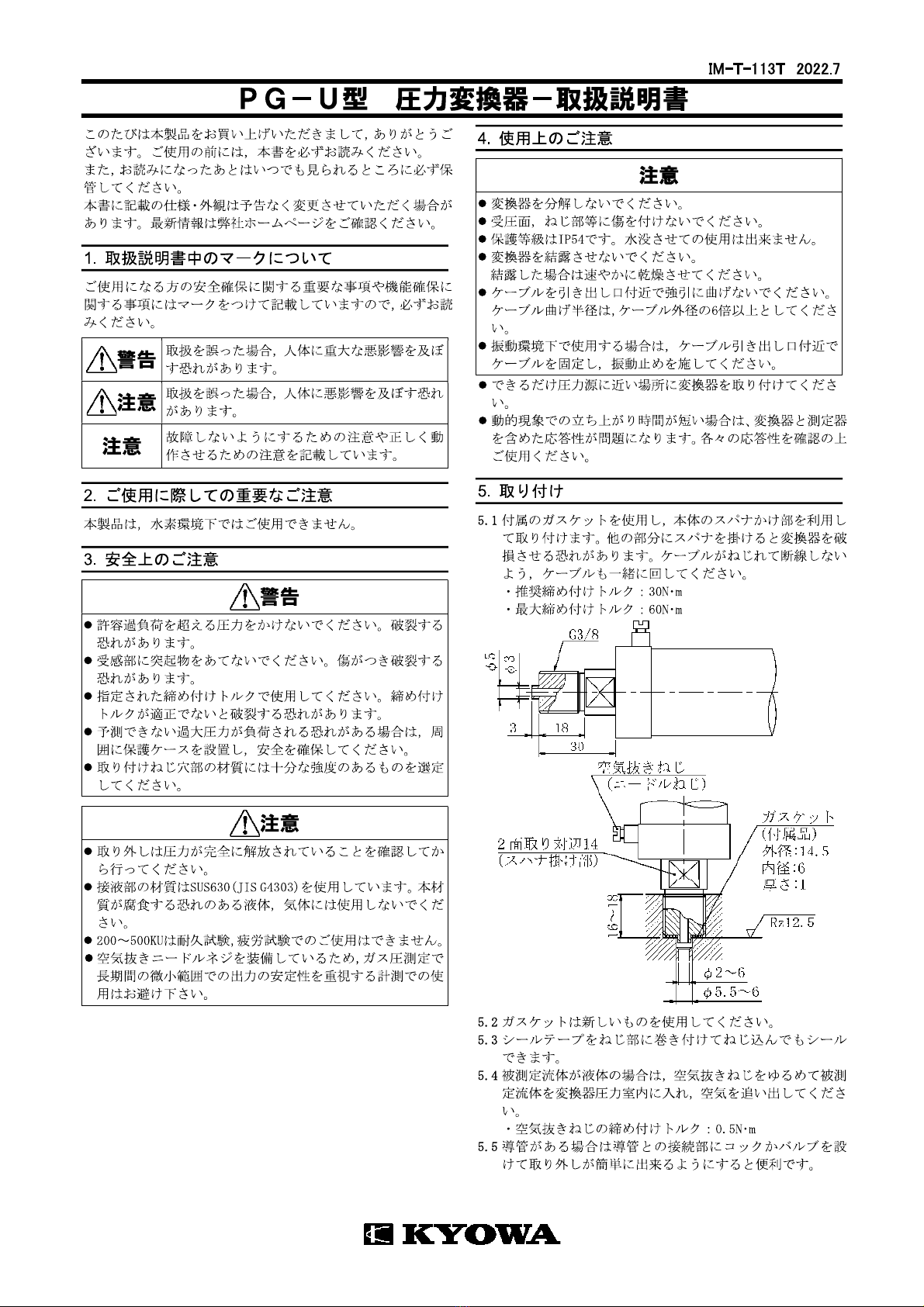
6. Con nectio n
6.1 Connect the transducer to a measuring instrument.
6. 2 When using a measuring instrument other than KYOWA, connector
plug as follows.
When connected the attached cable, shield wire is connected to the
case.
6. 3
Heat run for 5 minutes or longer before starting the measurement.
7. Co n v ers i o n
7. 1 Use the calibration constant described in the test data sheet to
convert a reading into a pressure value.
7 . 2
When a strain amplifier is in use, output reads in ×10-6 equivalent
strain. Find a pressure value corresponding to ×10-6 strain. Then,
obtain a pressure value through multiplication using the following
equation.
Pressure (Pa) = Strain amplifier’s output (×10-6 strain)
x Calibration constant (Pa
/
1×10⁻⁶ strain)
7. 3 When using an amplifier of other type or a recorder, first find the exact
bridge exciting voltage applied. Second, find the pressure value that
corresponds to 1(μV) output voltage against 1(V) bridge excitation
voltage. Then, obtain the pressure value through multiplication using
the following equation.
Pressure (Pa) =
Bridge output voltage (μV) ×Calibration constant (Pa
/
1μV/V)
Bridge excitation voltage (V)
Sensitivity Decrease due to Cable Extension
If a strain-gage transducer is connected to a signal conditioner, digital
indicator or strain amplifier via extension cable, we will not ignore the
sensitivity decrease due to the extension cable resistance which lowers
the voltage applied to the transducer.
The rated output with lowered sensitivity is obtained from the following
equation:
Rated output :ε
0
=(
R
)
ε
i
R+(r × L)
R
:
Transducer’s input resistance (Ω)
r
:
Extension cable’s reciprocating resistance (Ω/m)
L
:
Extension cable length (m)
ε
i
:
Rated output written in the Test data sheet
8. Storage and inspection
8. 1 Avoid water, oil, dust, etc. on the connector.
8. 2 Recommend calibrate the product once a year or so. (Contact your
KYOWA representative.)
8. 3 If suspicious outputs have occurred, check the input resistance,
output resistance and insulation resistance. Provided that the
connector operates properly and that the insulation resistance
between the mainframe and conductors is below 100MΩ, the cause
may be failure.
In this case, contact your KYOWA representative.
Ca u tio n
To measure insulation resistance, apply a voltage lower than 50V to
the insulation resistance tester.
9. Specifications
Models. Rated capacity. Natural frequency.
(Approx.)
PG-2KU 200kPa 2kHz
PG-5KU 500kPa 4kHz
PG-10KU 1MPa 7kHz
PG-20KU 2MPa 13kHz
PG-50KU 5MPa 21kHz
PG-100KU 10MPa 29kHz
PG-200KU 20MPa 40kHz
PG-300KU 30MPa 45kHz
PG-500KU 50MPa 50kHz
◆Performance
Rated Capacity See table above.
Nonlinearity Within ±0.2% RO (2,5,10KU: Within ±0.3% RO)
Hysteresis Within ±0.2% RO (2,5,10KU: Within ±0.3% RO)
Repeatability 0.1% RO or less
Rated Output 2mV/V±0.5% (2,5,10KU: ±1% RO or less)
◆Environmental Characteristics
Safe Temperature -20 to 70
℃
Compensated Temperature -10 to 60
℃
Temperature Effect on Zero W ithin ±0. 02% RO/
℃
Temperature Effect on Output W ithin ±0. 02% /
℃
◆Electrical Characteristics
Safe Excitation 15V AC or DC
Recommended Excitation 1 to 10V AC or DC
Input Resistance 350Ω ± 1%
Output Resistance 350Ω ± 1%
Accessory Cable 4-conductor (0.3mm2) chloroprene
(TT-01) shielded cable, 7.6mm diameter by 3m
long, terminated with a connector plug
Sensor side: 1108-12A10-7M
Measuring instrument side:
PRC03-12A10-7M
(When connected the attached cable,
shield wire is connected to the case.)
◆Mechanical Properties
Safe Overloads 150%
Natural Frequencies See table above.
Material Case: Anode oxidized coated aluminum
Liquid-contacting part: SUS630
For 10KU or more, the case is die case
zinc alloy.
Weight Approx.300g (2,5KU: Approx.500g)
(Excluding Cable)
Mounting Screw G3/8, male
Compliance Directive 2011/65/EU, (EU) 2015/863
(10 restricted substances) (RoHS)
[NOTE]
Products with CE Marking are compliant European RoHS Directive.
◆Accessories
Gasket (Mild copper) 3
Accessory Cable (TT-01) 1
Test Data Sheet 1
Instruction manual 1 (This book)