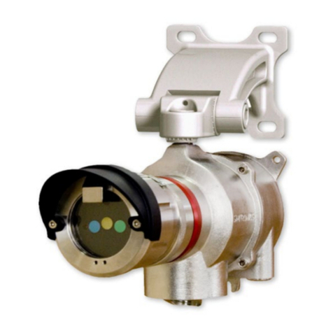
MC Smart Controls FL-1000 User manual

Full Product Manual
FL-1000

2
Table of Contents
INSTALLATION
3. Location
3. Mounting and Installation
3. Connecting the Power
SETUP
4. Communicating with the FL-1000
5. User Interface Home Page
6. Communications Configuration Page
7. FL-1000 User APP
8. Pre-Delivery/Install Checklist
9. Troubleshooting
10. Warranty and Disclaimer

Location
➢Select a location at least 6 inches or more after the main shutoff for the installation of the FL-1000
sensor. Make sure that the location you select in the main line after the shutoff valve is before the
pipe branches off.
Mounting and Installation (It is Strongly advised to contract a certified plumber)
1. Shut off the main valve that feeds the water to the house. See diagram 1
2. Cut a one inch piece out of the PEX water pipe(keep the piece you cut out). See diagram 2
3. Slip a crimp ring over both pieces of pipe. See diagram 2
4. Install the ¾ inch brass adapter (not included) between the two pieces of PEX pipe. See diagram 3
5. Crimp both crimp rings with the special crimping tool.
6. Take the one inch piece of PEX pipe that you cut out in step 2 and slip a crimp ring over one end
then slip it over the top of the brass tee and crimp it on with the special crimp tool. See diagram 4
7. Put a crimp ring over the open end of the one inch PEX and then slip the brass end of the sensor
into the open PEX. Crimp the crimp ring with the special crimp tool. See Diagram 5
8. Turn the main water valve back on and check for leaks.
Connect Line Power
➢Let the water run for a few minutes. If there are no leaks plug the AC power supply into the wall
outlet.
3
Installation
Diagram 1 Diagram 2 Diagram 3 Diagram 4 Diagram 5

4
Communicating with the FL-1000
There are two ways to communicate with the FL-1000 over WIFI:
Option 1: Connect to the FL-1000 as a WIFI network
While standing within 50 feet of the FL-1000 unit with a smart device. Look for local WIFI
network named FL-1000_xxxxxx = the last four characters of the specific FL-1000’s MAC address.
Example: FL-1000_030768. See Diagram 1 Below.
Select the FL-1000 network and enter the default password “FL-1000”This will connect you to
the unit and allow you to configure or control the unit directly. The default IP for this network is
“192.168.4.1.”
Once your are connected to the FL-1000 user interface you can choose to connect the device to
your local WIFI network.
Option 2: Connect to Local WIFI Network:
While connected to the FL-1000 via the on board WIFI network, go down to the communications
tab at the bottom of the screen. This will take you to the communications set up page.
Under the “Network Profile” scroll down menu select “Connect unit to internet via WIFI”Select
the “Wifi Network Scan” button and a list of all the local WIFI networks will appear.
Select the network that you would like to join.
Choose the security and enter the password. Hit save and the FL-1000 will connect to the
network and it will show up with a check mark when it is connected. See Diagram 2.
Diagram 1 Diagram 2

FL-1000 User Interface
Configure Button- This button will bring you to the communications configuration page. See next page.
Freeze Set Point- The temperature that is set by user. When the water Temperature goes below this
value an alarm is triggered and an email and or a text are sent.
Leak Alarm Status- This is triggered when a leak is detected. Am email and or a text are sent.
Freeze Alarm Status- This is triggered when the water temperature goes below the Freeze set point.
Test Button- Pressing the “Test” button will test for leaks manually within 10 seconds.
Start Time- This is the time window the user sets. This time window will be the time period in which the
FL-1000 will test for leaks in auto mode.

6
Communications Configuration Page
WiFI Station- This menu is where you configure and connect to your home local WIFI
network
WiFi Access Point- This menu is where you configure your communication parameters for
the FL-1000 WIFI network.

FL-1000 User APP
The APP can be downloaded for free and used to
Access the specific controller locally via the local
FL-1000 user interface access point or globally over
the internet

8
Pre-Delivery/Install Checklist
1) FL-1000 Leak/Freeze Sensor
2) 24 VDC power Adapter

9
Troubleshooting
Can you see the
FL-1000 network on
your smart device
Can you connect to the FL-
1000 network with your
smart device Reboot the FL-1000 If after rebooting the unit you still cannot
see the FL-1000 network or connect to it
the unit is defective.
Yes
Yes
No
No
The unit is defective.
No If WIFI network does not show up in Smart
Device WIFI network list the processor or
firmware is corrupted or defective or the WIFI
module is defective. Send controller back
Try to connect to the FL-1000
User Interface. Can you bring up
User Interface in Browser
Everything is working
continue setup

10
Warranty and Disclaimers
WARRANTY
Mani Group warrants that each product will be free of defects in material and
workmanship for a period of three (3) years for its products. The warranty
commences on the date the product is shipped by Mani Group. Mani Group’s sole
liability and responsibility under this warranty is to repair or replace any product
which is returned to it by the Buyer and which Mani Group determines does not
conform to the warranty. Product returned to Mani Group for warranty service
will be shipped to Mani Group at Buyer’s expense and will be reshipped to Buyer
at Mani Groups expense. In no event, shall Mani Group be responsible under this
warranty for any defect which is caused by negligence, misuse or mistreatment of
a product or for any unit which has been altered or modified in any way. The
warranty of replacement shall terminate with the three (3) years warranty of the
product.
Mani Group makes no warranties of any nature of kind, expressed or implied, with
respect to the hardware, software, and/or products and hereby disclaims any and
all such warranties, including but not limited to warranty of non-infringement,
implied warranties of merchantability for a particular purpose, any interruption or
loss of the hardware, software, and/or product, any delay in providing the
hardware, software, and/or product or correcting any defect in the hardware,
software, and/or product, or any other warranty. The Purchaser represents and
warrants that Mani Group has not made any such warranties to the Purchaser or
its agents MANI GROUP EXPRESS WARRANTY TO BUYER CONSTITUTES MANI
GROUP SOLE LIABILITY AND THE BUYER’S SOLE REMEDIES. EXCEPT AS THUS
PROVIDED, MANI GROUP DISCLAIMS ALL WARRANTIES, EXPRESS OR IMPLIED,
INCLUDING ANY WARRANTY OF MERCHANTABILITY OR FITNESS FOR A
PARTICULAR PROMISE.
Table of contents
Popular Security Sensor manuals by other brands
Extech Instruments
Extech Instruments 401050 user guide

Philips
Philips CHLORIDE COMPAC CXX Series instruction sheet

LINKIND
LINKIND LL20004 user manual

schmersal
schmersal AZ 16-STS30-02 operating instructions

Capital Safety
Capital Safety DBI-Sala Ultra-Lok RSQ 3504553 Specific instructions

A.E.B.
A.E.B. 1050 Assembly instructions

Workzone
Workzone 11334 user guide

Adixen
Adixen ASM 142 D user manual

Smartwares
Smartwares SMA-40151 instruction manual

UMAX Technologies
UMAX Technologies U-Smart Door Sensor user manual

B.E.G.
B.E.G. LUXOMAT PD4-M-2C-C Series Installation and operating instruction

Ecolink
Ecolink Firefighter CS-600 Installation manual & users guide