McAfee M-8000XC User manual

This Quick Start Guide explains how to quickly set up and activate your McAfee® Network Security Platform
M-8000XC Sensor to be load balanced by McAfee® Network Security Platform XC-240 Load Balancer. Cabling the
Sensor’s XFP (10 Gigabit Small Form-factor Pluggable) Monitoring ports into the XC-240 enables you to load balance
the Sensor trac.
To upgrade an existing M-8000 Sensor to M-8000XC, contact the Technical Support personnel of McAfee.
For more information on the XC-240 device, see the McAfee Network Security Platform XC-240 Load Balancer
Appliance Quick Start Guide.
All product documentation referenced in this Quick Start Guide is found on the McAfee Service Portal.
The Sensor front panel
1Power supply A (2-included) 7XFP 10 Gigabit Ethernet Monitoring ports (12)
2Power supply B (2-optional; sold separately) 8Compact Flash port (2)
3RS-232C Control port (2) 9RJ-45 Response port (1)
M-8000XC Sensor Quick Start Guide
Revision C
McAfee® Network Security Platform
1

4RS-232C Auxiliary port (2) 10 10/100/1000 Management port (1)
5RJ-11 Fail-Open Control ports (14) 11 Interconnect ports (2)
6SFP 1 Gigabit Ethernet Monitoring ports (16)
1 Position the Sensor
Details on all of the tasks are available in the McAfee Network Security Platform M-8000 Sensor Product Guide.
Also see McAfee Network Security Platform M-series Slide Rail Assembly Procedure.
aRelease the rails and attach inner rails (of a three-in-one set) to the chassis by fastening it with the screws
provided.
bAttach L-shape and external rails to the rack frame.
cInstall the primary Sensor into a rack and mount ears. You can also mid-mount the Sensor (optional).
2

dInstall the redundant power supply (optional).
eInstall modules in the Sensor's Monitoring ports.
fRepeat Steps a through e for the secondary Sensor.
2 Cable the Management and Console ports
aPlug a Category 5e Ethernet cable in the
Mgmt (Management) port of M-8000XC P.
bPlug the other end of the cable into the
network device connected to your Manager
server.
cPlug the DB9 Console cable supplied in the
Sensor box into the Console port (labeled
Console on the Sensor front panel) of
M-8000XC P.
You can use the Console port on
the secondary Sensor, M-8000XC
S, for a ash recovery process or
to troubleshoot.
dConnect the other end of the Console port
cable directly to a COM port of the computer or terminal server you will be using to congure the Sensor
(for example, a computer running correctly congured Windows Hyperterminal software). You must
connect directly to the console for initial conguration; you cannot congure the Sensor remotely.
3

The required settings for Hyperterminal are:
• Baud rate: 38400 • Stop Bits: 1
• Number of Bits: 8 • Control Flow: None
• Parity: None
ePlug the female end of a power cable into the power inlet and plug the other end into a power source.
The Sensor ships with standard U.S. power and international cables.
The M-8000XC does not have a power switch; you need to only plug the power cable into a
power source.
3 Cable the Monitoring ports
This procedure describes how to cable a Sensor to connect it to the XC-240 Load Balancer.
aPlug the cable appropriate for use with your XFP module into port 1A.
McAfee supports only those XFP modules purchased through McAfee or from a
McAfee-approved vendor.
Do not use XC ports. These ports are reserved for interconnection between the primary
(M-8000XC P) and secondary (M-8000XC S) Sensors.
bConnect the other end of the cable to a Sensor port on the XC-240 Load Balancer.
For instructions on using the XC-240 Load Balancer, see the McAfee Network Security Platform XC
Cluster Administration Guide.
4

4 Cable the interconnect ports
This procedure describes how to connect the primary Sensor to the secondary Sensor.
a
Plug the supplied Ethernet cable into the
XC1 port of the primary Sensor.
bConnect the other end of the Ethernet cable
used in a into the XC4 port of the secondary
Sensor.
cInsert the supplied XFP modules into the
XC2, XC3, XC5, and XC6 ports on the primary
and secondary Sensors.
McAfee supports only those XFP modules purchased through McAfee or from a
McAfee-approved vendor.
dPlug one end of an LC-LC ber-optic cable into the XC2 port of the primary Sensor and connect the other
cable to the XC5 port of the secondary Sensor.
ePlug one end of an LC-LC ber-optic cable into the XC3 port of the primary Sensor and connect the other
the cable to the XC6 port of the secondary Sensor.
5 Add the Sensor to the Manager
The Manager displays the Login ID page.
aLog on to the Manager. The default Login ID is admin and the default Password is admin123.
bClick Configure.
NAC is not supported on M-8000XC Sensors. You do not require a license le to enable IPS on
M-8000XC Sensors.
cTo add a Sensor in the Manager, select Device List | Devices, and then click New.
5

The Add New Device page is displayed.
dEnter information in the appropriate elds and click Save.
Remember the Shared Secret value entered at this step. This value is used while you congure
the Sensor.
For more information on the elds in Add New Device page, see McAfee Network Security Platform
XC Cluster Administration Guide.
6Congure Sensor information
Congure the Sensor with the network information, a name, and the shared secret key that the Sensor uses to
establish secure communication with the Manager. Use the name and key values you set in step 5d.
The rst time you congure a Sensor, you must have physical access to the Sensor.
You congure the M-8000XC Sensor using the CLI of the primary Sensor (M-8000XC P).
6

At any time during conguration, you can type a question mark (?) to get help on the Sensor CLI commands.
For a list of all commands, type commands.
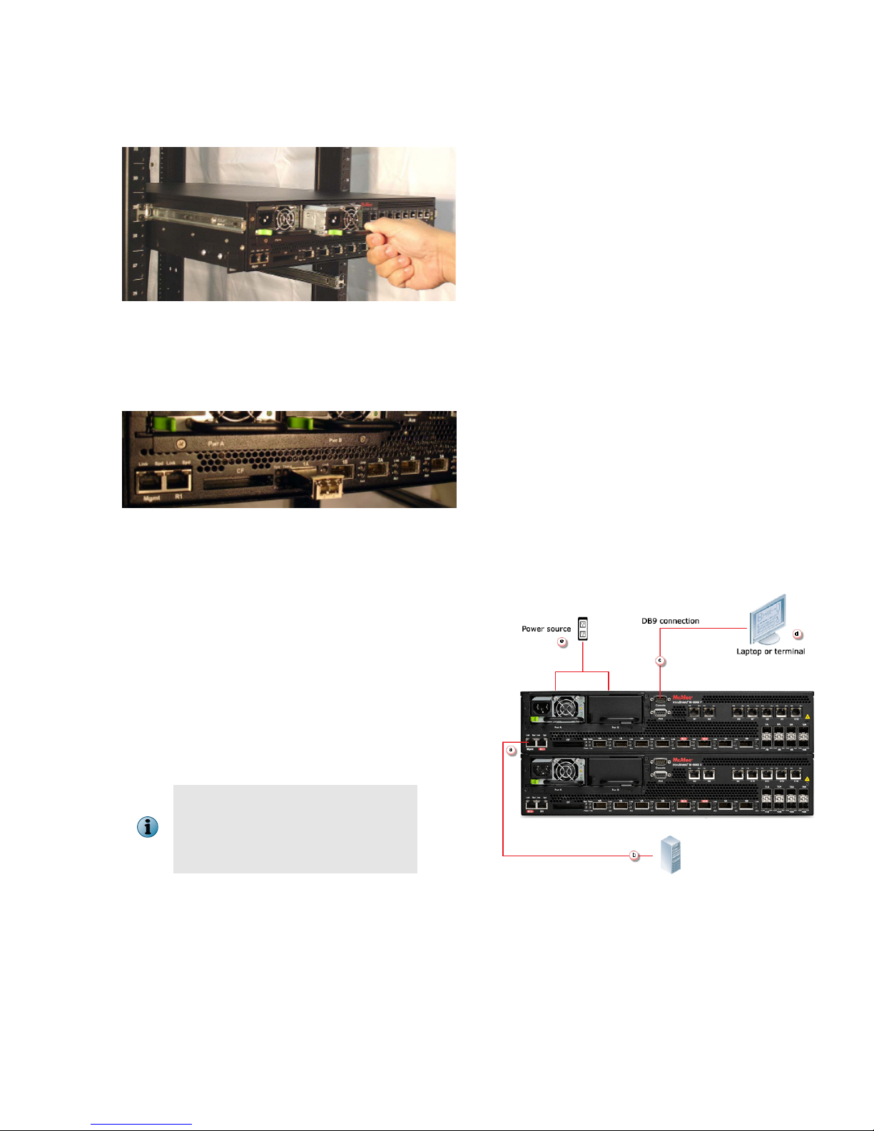
aLog on to the primary Sensor using the terminal connected to the Console port.
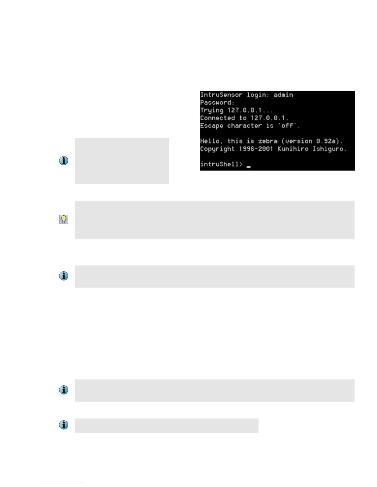
bAt the prompt, log on using the default Sensor username (admin) and password (admin123).
c[Optional, but recommended]. Change
the Sensor password. At the prompt,
type: passwd.The Sensor prompts you
to enter the new password and prompts
you for the old password.
A password must contain
between 8 to 25 characters, is
case-sensitive, and can consist
of any alphanumeric character
or symbol.
dSet the name of the Sensor:
You can enter the setup command at the prompt and this will automatically prompt you to
provide the information shown in items 4 through 7 and item 10. Or, you use the set command
instead. If you use the set command, you must manually enter the complete command syntax
as shown in items 4 through 7 and item 10.
At the prompt, type: set sensor name <word>.
Example: set sensor name HR_sensor1
The Sensor name is a case-sensitive character string up to 25 characters. The string can include
hyphens, underscores, and periods, and must begin with a letter.
eIf the Sensor is not on the same network as the Manager, set the address of the default gateway. At the
prompt, type: set sensor gateway <A.B.C.D>
Example: set sensor gateway 192.168.3.68
fSet the IP address of the Manager server. At the prompt, type: set manager ip <A.B.C.D>.
Example: set manager ip 192.168.2.8
gSet the IP address and subnet mask of the Sensor. At the prompt, type: set sensor ip <A.B.C.D>
<E.F.G.H>.
Example: set sensor ip 192.168.2.12 255.255.255.0
Specify an IP address using four octets separated by periods: X.X.X.X, where X is a number
between 0 and 255, followed by a subnet mask in the same format.
hIf prompted, reboot the Sensor. Type: reboot
The Sensor can take up to ve minutes to complete its reboot.
7

iPing the Manager from the Sensor to determine if your conguration settings to this point have
successfully established the Sensor on the network. At the prompt, type: ping <manager IP
address>.
If the ping is successful, continue with the following steps. If not, type show to verify your conguration
settings and check that the information is correct.
jSet the shared secret key value for the Sensor. At the prompt, type: set sensor sharedsecretkey.
The Sensor then prompts you to enter and, subsequently, conrm the shared secret key value.
This value is used to establish a trust relationship between the Sensor and the Manager. The
secret key value can be between 8 and 25 characters of any ASCII text. The shared key value is
case-sensitive. Make sure the value matches the shared secret key value you provided in the
Manager interface.
kTo verify the conguration information, type show. Check that all information is correct.
lTo exit the session, type exit.
7 Verify successful installation
A handshake process begins between the Sensor and the Manager. The devices will take a few seconds to
establish communication.
Perform the following steps to verify successful communication between the Sensor and the Manager.
aIn the Sensor CLI, type: status.
The status report appears
bReturn to the Manager. In the Manager Home page, view the Manager status in the System Health section.
Manager status should be up and Sensor status should be active.
cFrom the Manager Home page, click Configure to open the Configuration page.
dSelect your added Sensor: Device List | Sensor_Name. The ports for this Sensor appear under the
Sensor_Name node.
Device_Name indicates the name of the Sensor you added.
eSelect Device List | Device_Name | Port Settings.
fClick the button representing the ports on the Sensor that you cabled. Ensure that your port settings
match the cabling.
8

8 You're up and running!
Your Sensor is actively monitoring connected segments and communicating with the Manager for
administration and management operations.
aRead McAfee Network Security Platform Quick Tour for an overview of the system. For detailed usage
instructions, see McAfee Network Security Platform Installation Guide and McAfee Network Security Platform
IPS Administration Guide, or click the Detailed Help buttons in the upper-right corner of each window in the
Manager.
bLaunch the Threat Analyzer from the Home page to view alert statistics as attacks are detected. These will
display in the Unacknowledged Alert Summary area of the Manager Home page.
cHaving problems? Check McAfee Network Security Platform Troubleshooting Guide for troubleshooting
information.
dNote that most deployment problems stem from conguration mismatches between the Sensor and the
network devices to which it is connected. Check your duplex and auto-negotiation settings on both
devices to ensure they are synchronized.
If you need to contact Technical Support, go to https://mysupport.mcafee.com.
9

10

11

Copyright © 2017 McAfee, LLC
McAfee and the McAfee logo are trademarks or registered trademarks of McAfee, LLC or its subsidiaries in the US and other countries. Other
marks and brands may be claimed as the property of others.
12 700-3505C00
Table of contents
Other McAfee Accessories manuals

McAfee
McAfee IFO-M65K-ISAA - Network Security Platform M-6050... User manual

McAfee
McAfee IIP-M80K-ISAA - Network Security Platform... User manual

McAfee
McAfee IIP-S14C-NA-100I - IntruShield 1400 Sensor... User manual

McAfee
McAfee IIP-M65K-ISAA - Network Security Platform... User manual

McAfee
McAfee IIP-S41K-NA-100I - IntruShield 4010 Sensor... User manual

McAfee
McAfee IIP-M15K-ISAA - Network Security Platform... User manual

McAfee
McAfee M-2850 User manual

McAfee
McAfee IIP-S03K-NA-100I - IntruShield 3000 Sensor... User manual