Dragino LHT65 User manual

www.dragino.com
LHT65 Temperature & Humidity sensor 1 / 56
LHT65 Temperature & Humidity Sensor User Manual
Document Version: 1.8.0
Image Version: v1.8
Version
Description
Date
0.9
Draft
2019-May-14
1.0
Release
2019-Jun-15
1.1
Modify activation process, Add TTN Payload Decode
2019-Aug-28
1.2
Fix ACT typo, Add cayenne photo. Battery Analyze. Add notice for single
channel use. Add trouble shooting.
2019-Nov-27
1.3
Add External Temperature Sensor pin connection, Improve ST-Link v2
connection description.
2019-Dec-29
1.3.1
Correct myDevices description
2019-Dec-31
1.3.2
Add how to reset device
2020-Jan-17

www.dragino.com
LHT65 Temperature & Humidity sensor 2 / 56
1.5.0
Update Alarm mode description from firmware v1.5
2020-Feb-25
1.7.0
Update Battery Report,FAQ,Update Payload and connection for v1.7 firmware
2020-May-31
1.7.1
Add Sensor probe E3
2020-Jun-9
1.7.2
Fix typo for A2 downlink command to change Interrupt
2020-Jun-30
1.7.3
Fix typo for uplink interval , it should be 20 minutes in default settings
2020-Jul-15
1.8.0
Upgrade to v1.8 firmware,
Add Datalog feature, update to LoRaWAN stack DR-LWS-005
2021-Jan-29

www.dragino.com
LHT65 Temperature & Humidity sensor 3 / 56
1. Introduction..............................................................................................................................6
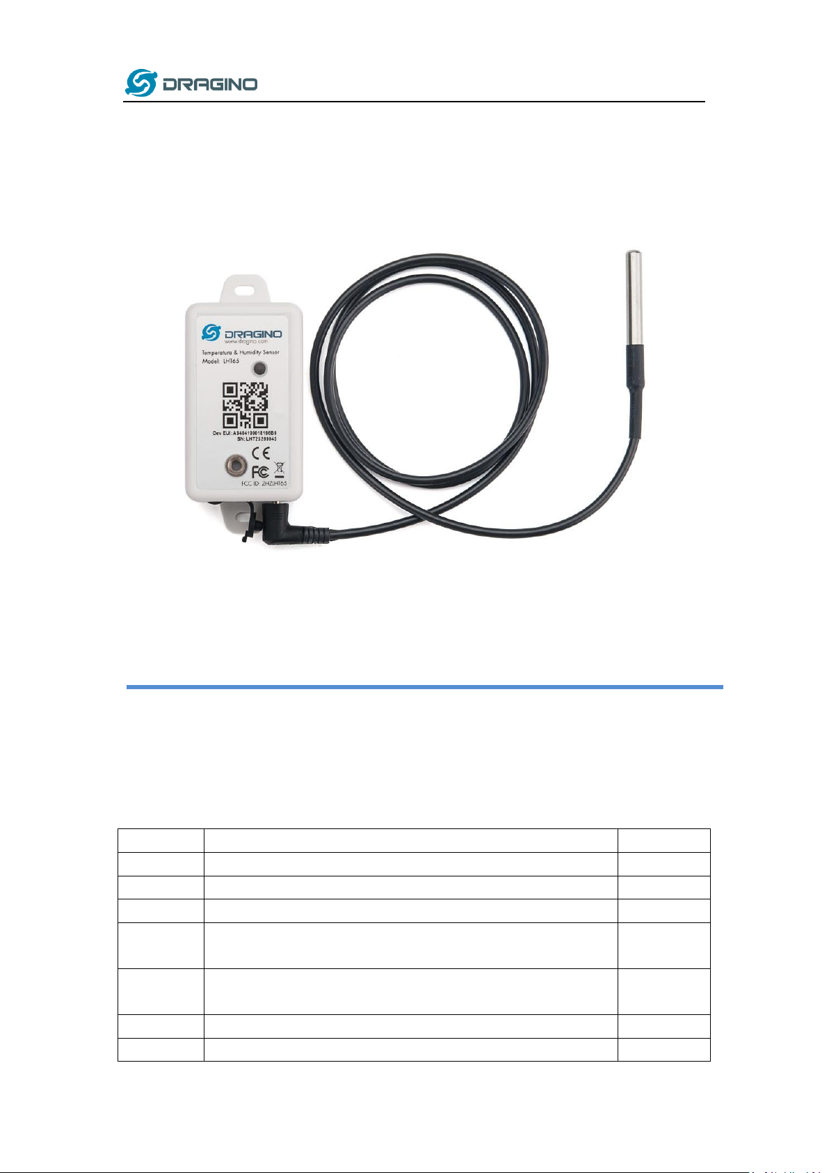
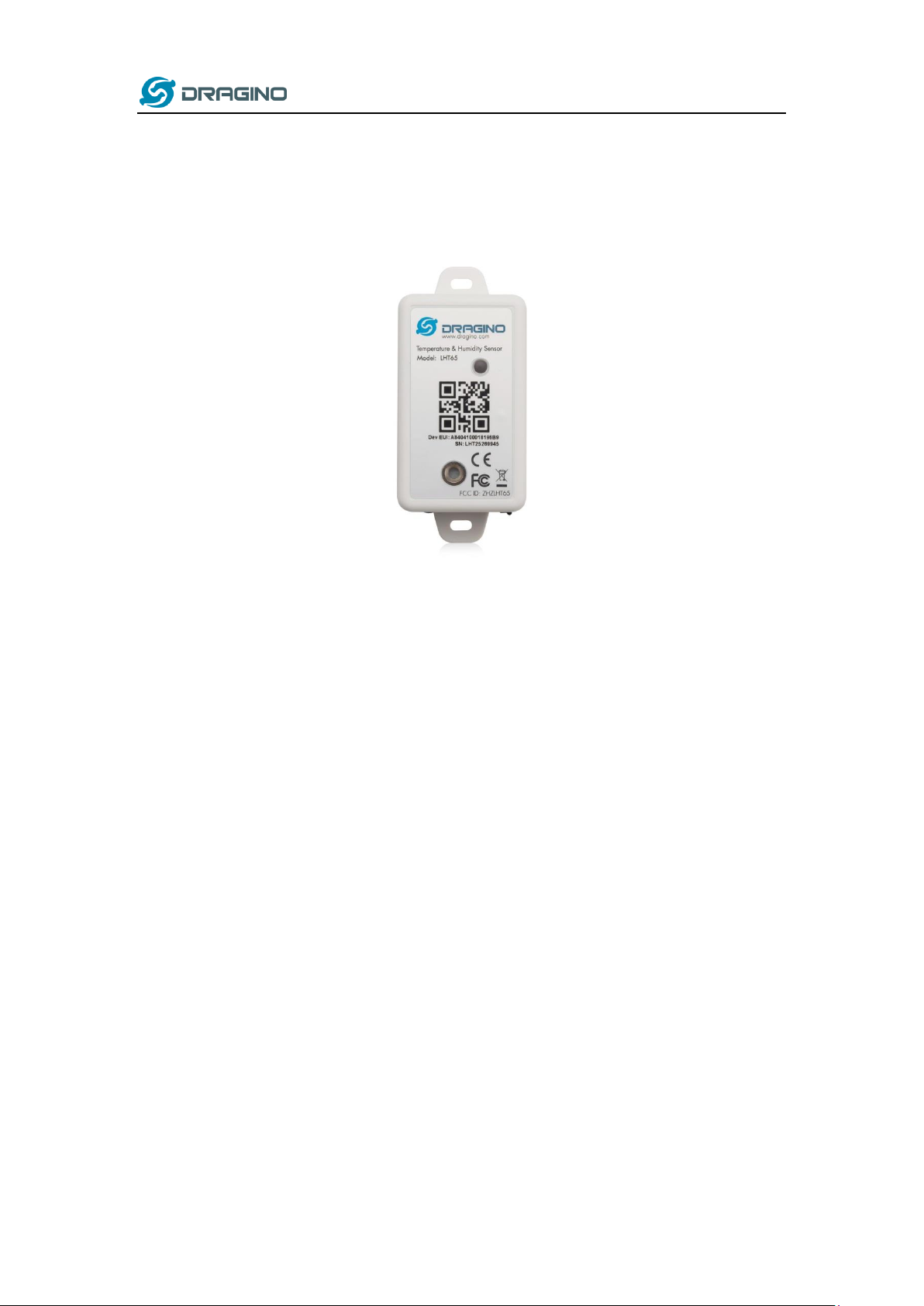
1.1 What is LHT65 Temperature & Humidity Sensor ........................................................................6
1.2 Features......................................................................................................................................7
1.3 Specifications..............................................................................................................................7
1.4 Power Consumption ...................................................................................................................8
1.5 Storage & Operation Temperature.............................................................................................9
1.6 Applications................................................................................................................................9
2. Operation Mode .....................................................................................................................10
2.1 How to activate LHT65? ...........................................................................................................10
2.2 How it works?...........................................................................................................................10
2.3 Example to join LoRaWAN network..........................................................................................10
2.4 Uplink Payload..........................................................................................................................12
2.4.1 Decoder in TTN ...............................................................................................................13
2.4.2 BAT-Battery Info..............................................................................................................13
2.4.3 Built-in Temperature.......................................................................................................14
2.4.4 Built-in Humidity.............................................................................................................14
2.4.5 Ext # ................................................................................................................................14
2.4.6 Ext value .........................................................................................................................14
2.4.7 Ext=1, E1 Temperature Sensor........................................................................................15
2.4.8 Ext=4, Interrupt Sensor...................................................................................................16
2.4.9 Ext=5, E5 Illumination Sensor .........................................................................................18
2.4.10 Ext=6, ADC Sensor ..........................................................................................................19
2.4.11 Ext=7, Counting Sensor...................................................................................................20
2.4.12 Ext=8, Counting Sensor ( 4 bytes) ...................................................................................21
2.4.13 Ext=9, E1 sensor with Unix Time stamp..........................................................................23
2.5 Show data on MyDevices .........................................................................................................23
2.6 Datalog Feature........................................................................................................................27
2.6.1 Unix TimeStamp..............................................................................................................27
2.6.2 Set Device Time ..............................................................................................................27
2.6.3 Poll sensor value .............................................................................................................28
2.6.4 Datalog Uplink payload...................................................................................................29
2.7 Alarm Mode..............................................................................................................................30
2.8 LED Indicator ............................................................................................................................32
3. Configure LHT65 via AT Command or LoRaWAN Downlink......................................................33

www.dragino.com
LHT65 Temperature & Humidity sensor 4 / 56
3.1 Set Transmit Interval Time........................................................................................................33
3.2 Set External Sensor Mode.........................................................................................................34
3.3 Enable/Disable uplink DS18B20 probe ID.................................................................................35
3.4 Set Password ............................................................................................................................35
3.5 Quit AT Command ....................................................................................................................35
3.6 Set to sleep mode .....................................................................................................................36
3.7 Set system time ........................................................................................................................36
3.8 Set Time Sync Mode .................................................................................................................36
3.9 Set Time Sync Interval ..............................................................................................................37
3.10 Print data entries base on page...........................................................................................37
3.11 Print last few data entries....................................................................................................38
3.12 Clear Flash Record ...............................................................................................................38
4. Battery & How to replace........................................................................................................39
4.1 Battery Type .............................................................................................................................39
4.2 Replace Battery ........................................................................................................................39
4.3 Power Consumption Analyze....................................................................................................40
5. Sensors & Accessories.............................................................................................................41
5.1 E1 Temperature Probe..............................................................................................................41
5.2 E2 Extension Cable ...................................................................................................................41
5.3 E3 Temperature Probe..............................................................................................................42
5.4 E5 Illumination Probe ...............................................................................................................43
6. FAQ.........................................................................................................................................44
6.1 How to use AT Command to configure LHT65 ..........................................................................44
6.2 How to upgrade the firmware? ................................................................................................47
6.3 How to change the LoRa Frequency Bands/Region? ................................................................51
6.4 How to set up LHT65 to work with Single Channel Gateway such as LG01/LG02? ..................51
6.5 How to reset LHT65? ................................................................................................................53
6.6 What is the frequency plan of LHT65? .....................................................................................53
6.7 Why I see packet payload is 00?...............................................................................................53
7. Trouble Shooting.....................................................................................................................53

www.dragino.com
LHT65 Temperature & Humidity sensor 5 / 56
7.1 AT Command input doesn’t work .............................................................................................53
7.2 Why the temperature shows 327.67
℃
?..................................................................................53
7.3 Device no responses after Interrupt during upload or configure?............................................54
7.4 Have trouble to register to US915 or AU915 frequency band ..................................................54
8. Order Info ...............................................................................................................................55
9. Packing Info ............................................................................................................................55
10. Support ..............................................................................................................................56
11. FCC Warning.......................................................................................................................56

www.dragino.com
LHT65 Temperature & Humidity sensor 6 / 56
1. Introduction
1.1 What is LHT65 Temperature & Humidity Sensor
The Dragino LHT65 Temperature & Humidity sensor is a Long Range LoRaWAN Sensor. It includes
a built-in SHT20 Temperature & Humidity sensor and has an external sensor connector to
connect to external sensors such as Temperature Sensor, Illumination sensor, Interrupt Sensor,
ADC sensor etc .
The LHT65 allows users to send data and reach extremely long ranges. It provides ultra-long
range spread spectrum communication and high interference immunity whilst minimizing current
consumption. It targets professional wireless sensor network applications such as irrigation
systems, smart metering, smart cities, building automation, and so on.
LHT65 has a built-in 2400mAh non-chargeable battery which can be used for more than 10
years*.
LHT65 is full compatible with LoRaWAN v1.0.3 Class A protocol, it can work with standard
LoRaWAN gateway.
LHT65 has 3200 data records with datetime which can be retrieved with datetime for further
analyze.
*The actually battery life depends how often to send data, please see battery analyzer chapter.

www.dragino.com
LHT65 Temperature & Humidity sensor 7 / 56
1.2 Features
✓Wall mountable
✓LoRaWAN v1.0.3 Class A protocol
✓Frequency Bands: CN470/EU433/KR920/US915/EU868/AS923/AU915
✓AT Commands to change parameters
✓Remote configure parameters via LoRaWAN Downlink
✓Firmware upgradable via program port
✓Built-in 2400mAh battery for more than 10 year use.
✓Built-in Temperature & Humidity sensor
✓Optional External Sensors
✓Tri-color LED to indicate status
✓Datalog feature
1.3 Specifications
Built-in Temperature Sensor:
➢Resolution: 0.01 °C
➢Accuracy Tolerance : Typ °C
➢Long Term Drift: < 0.02 °C/yr
➢Operating Range: -40 ~ 125 °C
Built-in Humidity Sensor:
➢Resolution: 0.04 %RH
➢Accuracy Tolerance : Typ
➢Long Term Drift: < 0.02 °C/yr
➢Operating Range: 0 ~ 100 °C
External Temperature Sensor – E1:
➢Resolution: 0.0625 °C
➢±0.5°C accuracy from -10°C to +85°C
➢±2°C accuracy from -55°C to +125°C
➢Operating Range: -55 °C ~ 125 °C
External Illumination Sensor – E5:
➢Resolution: 1 lx
➢Range: 0-65535 lx
➢Operating Range: -40 °C ~ 85 °C

www.dragino.com
LHT65 Temperature & Humidity sensor 8 / 56
1.4 Power Consumption
LHT65 (without external sensor): Idle: 3uA. Transmit: max 130mA.
LHT65 + E1 Temperature Sensor: Idle: 4uA, Transmit: max 130mA.
LHT65 + E5 Illumination Sensor: Idle: 4uA, Transmit: max 130mA.

www.dragino.com
LHT65 Temperature & Humidity sensor 9 / 56
1.5 Storage & Operation Temperature
-40°C to +85°C
1.6 Applications
✓Smart Buildings & Home Automation
✓Logistics and Supply Chain Management
✓Smart Metering
✓Smart Agriculture
✓Smart Cities
✓Smart Factory

www.dragino.com
LHT65 Temperature & Humidity sensor 10 / 56
2. Operation Mode
2.1 How to activate LHT65?
The LHT65 has two working modes:
✓Deep Sleep Mode: LHT-65 doesn’t have any LoRaWAN activate. This mode is used for
storage and shipping to save battery life.
✓Working Mode: In this mode, LHT65 will works as LoRaWAN Sensor mode to Join LoRaWAN
network and send out the sensor data to server. Between each sampling/tx/rx periodically,
LHT65 will be in STOP mode (IDLE mode), in STOP mode, device has the same power
consumption as Deep Sleep mode.
The LHT65 is set in deep sleep mode by default; The ACT button on the bottom of device is used
to switch to different modes:
Behavior on ACT
Function
Action
Pressing ACT
between 1s < time
< 3s
Test uplink
status
If LHT65 is already Joined to LoRaWAN network, LHT65
will send an uplink packet, if LHT65 has external sensor
connected, blue led will blink once. If LHT65 has not
external sensor, red led will blink once.
Pressing ACT for
more than 3s
Active Device
green led will fast blink 5 times, device will enter working
mode and start to JOIN LoRaWAN network. green led will
solid turn on for 5 seconds after joined in network.
Fast press ACT 5
times.
Deactivate
Device
red led will solid on for 5 seconds. Means LHT65 are in
Deep Sleep Mode.
2.2 How it works?
The LHT65 is configured as LoRaWAN OTAA Class A mode by default. Each LHT65 is shipped with
a worldwide unique set of OTAA and ABP keys. To use LHT65 in a LoRaWAN network, user needs
to input the OTAA or ABP keys in the network server. So LHT65 can join the LoRaWAN network
and start to transmit sensor data. The default period for each uplink is 20 minutes.
In case user can’t set the OTAA keys in the network server and has to use the existing keys from
server. User can use AT Command to set the keys in LHT65.
2.3 Example to join LoRaWAN network
This section shows an example for how to join the TTN LoRaWAN IoT server. Use with other
LoRaWAN IoT server is of similar procedure.

www.dragino.com
LHT65 Temperature & Humidity sensor 11 / 56
Assume the LG308 is already set to connect to TTN network . We need to add the LHT65 device in
TTN:
Step 1: Create a device in TTN with the OTAA keys from LHT65.
Each LHT65 is shipped with a sticker with the default device EUI as below:
User can enter these keys in the LoRaWAN Server portal. Below is TTN screen shot:
Add APP EUI in the application.
Add APP KEY and DEV EUI

www.dragino.com
LHT65 Temperature & Humidity sensor 12 / 56
Step 2: Use ACT button to activate LHT65 and it will auto join to the TTN network. After join
success, it will start to upload sensor data to TTN and user can see in the panel.
2.4 Uplink Payload
The uplink payload includes totally 11 bytes. Uplink packets use FPORT=2 and every 20 minutes
send one uplink by default.
After each uplink, the BLUE LED will blink once.
Size(bytes)
2
2
2
1
4
Value
BAT
Built-In
Temperature
Built-in
Humidity
Ext #
Ext value
First 6 bytes: has fix meanings for every device.
The 7th byte (EXT #): defines the external sensor model.
The 8th ~ 11th byte: the value for external sensor value. The definition is based on external sensor
type. (If EXT=0, there won’t be these four bytes.)

www.dragino.com
LHT65 Temperature & Humidity sensor 13 / 56
2.4.1 Decoder in TTN
Please check the decoder from this link:
http://www.dragino.com/downloads/index.php?dir=LHT65/payload_decode/
2.4.2 BAT-Battery Info
These two bytes of BAT include the battery state and the actually voltage
Bit(bit)
[15:14]
[13:0]
Value
BAT Status
00(b): Ultra Low ( BAT <= 2.50v)
01(b): Low (2.50v <=BAT <= 2.55v)
10(b): OK (2.55v <= BAT <=2.65v)
11(b): Good (BAT >= 2.65v)
Actually BAT voltage
Check the battery voltage for LHT65.
➢BAT status=(0xCBF6>>14)&0xFF=11(B),very good
➢Battery Voltage =0xCBF6&0x3FFF=0x0BF6=3062mV

www.dragino.com
LHT65 Temperature & Humidity sensor 14 / 56
2.4.3 Built-in Temperature
➢Temperature: 0x0B0D/100=28.29℃
➢Temperature: (0xF5C6-65536)/100=-26.18℃
2.4.4 Built-in Humidity
➢Humidity: 0x0376/10=88.6%
2.4.5 Ext #
Bytes for External Sensor:
EXT # Value
External Sensor Type
0x01
Sensor E1, Temperature Sensor
0x04
Sensor E4, Interrupt Sensor
0x05
Sensor E5, Illumination Sensor
0x06
Sensor E6, ADC Sensor
0x07
Sensor E7, Counting Senor,16 bit count
0x08
Sensor E7, Counting Senor,32 bit count
0x09
Sensor E1, Temperature Sensor, Datalog Mod
2.4.6 Ext value

www.dragino.com
LHT65 Temperature & Humidity sensor 15 / 56
2.4.7 Ext=1, E1 Temperature Sensor
➢DS18B20 temp=0x0ADD/100=27.81℃
The last 2 bytes of data are meaningless
➢DS18B20 temp= (0xF54F-65536)/100=-27.37℃
The last 2 bytes of data are meaningless
If the external sensor is 0x01, and there is no DS18B20 connected. The temperature will be set to
7FFF which is 327.67℃

www.dragino.com
LHT65 Temperature & Humidity sensor 16 / 56
2.4.8 Ext=4, Interrupt Sensor
In this mode, user can connect external interrupt sensor to the E2 Extension Cable to check
the open/close status from the sensor. For example, it can be used to connect to a door
sensor to check the open / close status, or connect to a mercury switch to detect the titling.
(NOTE: This feature only supported by SN number > LHT65307029)
Above is connection to a mercury switch, rotate the mercury will generate interrupt. LHT65
will detect it and send an uplink package to sever. User can also connect PA9 and PA10
together, with these two pins shortcut, LHT65 will know if the probe is connected well in the
socket.
User can use AT Command to set the method to detect Interrupt:
AT+EXT=4,1
Sent uplink packet in both rising and falling interrupt
AT+EXT=4,2
Sent uplink packet only in falling interrupt
AT+EXT=4,3
Sent uplink packet only in rising interrupt
Or use downlink command A2
Payload explain:

www.dragino.com
LHT65 Temperature & Humidity sensor 17 / 56
Means: The device is set to connect to an Interrupt Sensor, the cable connection is fine. This
packet is for a normal uplink, pin level is high.
Means: The device is set to connect to an Interrupt Sensor, the cable connection is fine. This
packet is for a Interrupt uplink, pin level is low.
Means: The device is set to connect to an Interrupt Sensor, the cable connection is losing.
(Notice: PA9 and PA10 must be connected to detect if cable is losing or fine.).

www.dragino.com
LHT65 Temperature & Humidity sensor 18 / 56
2.4.9 Ext=5, E5 Illumination Sensor
Means: The device is set to connect to an Illumination sensor, the cable connection is fine.
This strength of illumination is 401 lux
Means: The device is set to connect to an Illumination sensor, the cable connection is losing.

www.dragino.com
LHT65 Temperature & Humidity sensor 19 / 56
2.4.10 Ext=6, ADC Sensor
In this mode, user can connect external ADC sensor to check ADC value. The 3V3_OUT can
be used to power the external ADC sensor; user can control the power on time for this
sensor by setting:
AT+EXT=6,timeout Time to power this sensor, from 0 ~ 65535ms
For example:
AT+EXT=6,1000 will power this sensor for 1000ms before sampling the ADC value.
Or use downlink command A2 to set the same.
User can also connect PA9 and PA10 together, with these two pins shortcut, LHT65 will know
if the probe is connected well in the socket.
Means: The device is set to connect to an ADC sensor, the cable connection is fine. This
voltage detected is 2.822v.
Means: The device is set to connect to an ADC Sensor, but the cable connection is losing.
(Notice: PA9 and PA10 must be connected to detect if cable is losing or fine.).

www.dragino.com
LHT65 Temperature & Humidity sensor 20 / 56
2.4.11 Ext=7, Counting Sensor
In this mode, user can connect external interrupt sensor to the E2 Extension Cable for
counting purpose. Whenever there is an interrupt from this sensor, the ext value will
increase by 1.
(NOTE: This feature only supported by SN number > LHT65307029)
Above is connection to a mercury switch, rotate the mercury will generate interrupt. LHT65
will count it. It will periodically the counting value to server. User can also connect PA9 and
PA10 together, with these two pins shortcut, LHT65 will know if the probe is connected well
in the socket.
User can use AT Command to set the method to detect counting:
AT+EXT=7,0
Count at falling interrupt
AT+EXT=7,1
Count at raising interrupt
AT+SETCNT=60
Sent current count to 60
Or use downlink command A2
Other manuals for LHT65
1
Table of contents
Other Dragino Accessories manuals

Dragino
Dragino LLDS40 User manual

Dragino
Dragino LoRaWAN LDS02 User manual

Dragino
Dragino LHT65 User manual

Dragino
Dragino LDS01 User manual

Dragino
Dragino LSE01 User manual

Dragino
Dragino LWL01 User manual

Dragino
Dragino LDDS04 User manual

Dragino
Dragino LHT52 User manual

Dragino
Dragino LoRaWAN LiDAR ToF User manual

Dragino
Dragino LDS03A User manual
Popular Accessories manuals by other brands

Philips
Philips SVC2520W Specification sheet

HomeMatic
HomeMatic HmIP-SRD Mounting instruction and operating manual

Berker
Berker RolloTec Operation and assembly instructions

Honeywell
Honeywell RCW100N Specifications

Philips
Philips Sonicare AirFloss Ultra HX8401/03 manual

Alphalux
Alphalux SureScan ALXPIR instructions