MCC CM82 Installation manual

WARNING: For your own safety and effective operation, read this Safety and Operating Manual
carefully and completely before assembling and operating this unit. Failure to
understand and follow the contents of this manual may result in electrical shock, fire
and/or serious personal in ury.
SAFETY AND OPERATING MANUAL
CONDUIT PIPE THREADING MACHINE
MODEL NO. CM82
Please record your machine Serial No. which are located on nameplate
Serial No.
Keep his manual for fu ure reference.

2
CONTENTS
Safe y Informa ion ・・・・・・・・・・・・・・・・・・・・・・・・ 3
Par s Name ・・・・・・・・・・・・・・・・・・・・・・・・ 6
Descrip ion, Specifica ion and S andard accessories ・・・・・・・・・・・ 7
Preparing for Opera ion ・・・・・・・・・・・・・・・・・・・・・・・・ 8
1. Machine Inspection ・・・・・・・・・・・・・・・・・・・・・・・・ 8
2. Machine and Work Area Set-Up ・・・・・・・・・・・・・・・・・・・・ 8
3. Cutting Oil Lubrication ・・・・・・・・・・・・・・・・・・・・・・・・ 9
Machine Opera ion ・・・・・・・・・・・・・・・・・・・・・・・ 10
1.Electrical Requirement ・・・・・・・・・・・・・・・・・・・・・・・ 10
2. To Replace Dies ・・・・・・・・・・・・・・・・・・・・・・・ 10
3. To Replace Die Head ・・・・・・・・・・・・・・・・・・・・・・・ 11
4. High Speed and Low Speed ・・・・・・・・・・・・・・・・・・・ 12
5. To Cut Thread ・・・・・・・・・・・・・・・・・・・・・・・ 12
6. Cutting Oil ・・・・・・・・・・・・・・・・・・・・・・・ 13
7. Maintenance and Inspection ・・・・・・・・・・・・・・・・・・・ 13
8. Chamfering ・・・・・・・・・・・・・・・・・・・・・・・・・・・ 13

3
WARNING: Failure to obey a safety warning can result in serious in ury to yourself or to others.
Always follow the safety precaution to reduce the risk of fire, electric shock, and
personal in ury.
CAUTION: Failure to obey a safety warning may result in property damage or personal in ury.
Always follow the safety precaution to reduce the risk of fire, electric shock, and
personal in ury.
NOTE: Advises you of information instructions vital to the operation or maintenance of the
equipment.
SAFETY INFORMATION
1. Safe y Symbols
The purpose of safety symbols is to attract your attention to possible dangers.
The safety symbols, and the explanations with them, deserve your careful attention and understanding.
The safety warnings do not by themselves eliminate any danger.
The instructions or warnings they give are not substitutes for proper accident prevention measures.
SYMBOL MEANING
2. General Safe y
1)
Read all these instructions in this manual completely and carefully for your protection against
serious in uries.
2)
Save this manual. Refer to them frequently and use them to instruct other users.
3. Personal Safe y
1)
Stay alert, watch what you are doing and use common sense when operating a power tool. Never
operate machine when tired or under the influence of drugs or alcohol. A moment of inattention
while operating machine may result in serious personal in ury.
2)
Do not wear gloves, loose clothing or ewelry that can get caught in machine's moving parts and
cause serous in ury. Cover up or tie up long hair. Keep sleeves and ackets buttoned for reduction
of risk any accident.
3)
Always wear safety glasses.
4)
Protect your hearing by earmuffs or earplugs. If you use machine daily or in a noisy area.
5)
Protect your lungs by using dust mask when work area is dusty.
6)
Keep your hands and face away from dies, cutter blade, auto-chuck or other moving parts.
7)
Avoid accidental starting. Make sure switch is OFF position before plugging in. Plugging in tools in
that have the switch ON invites accidents.
8)
Keep hands away from rotating die head or any parts. Stop the machine before wiping pipe or
screw. Allow the machine to come to a complete stop before touching the pipe, machine chucks,
or any rotating parts. This practice will prevent serious in ury.
9)
Do not over-reach. Keep proper footing and balance at all times. Proper footing and balance
enables better control of the tool in unexpected situations.
10)
Unplug power cord when not in use, before making any ad ustments, changing accessories, or
storing the tools. Such prevention safety measures reduce risk of starting tool accidentally.
4. Elec rical Safe y
1) In the event of a malfunction or breakdown, grounding provides a path of least resistance for
electric current to reduce the risk of electric shock. This tool is equipped with an electric cord
having an equipment-grounding conductor and a grounding plug. The plug must be plugged into a
matching outlet that is properly installed and grounded in accordance with all local codes and

4
ordinances. Never modify the plug provided – if it will not fit the outlet, have the proper outlet
installed by a qualified electrician.
2) Avoid body contact with grounded surfaces. If your body is grounded, There is an increased risk
of electrical shock
3) Never expose electrical tools to rain or wet condition. Water entering a tool will increase the risk of
electrical accident.
4) Do not abuse cord. Never carry machine by the cord or yank the cord to disconnect it from outlet.
Keep cord from heat, oil, sharp edges or moving parts. Replace damaged cords immediately.
Damaged cords will cause the risk of electrical shock.
5) When used outdoors, use only extension cord intended for use outdoors and so marked.
6) Use only three-wire extension cords which have three-prong grounding plugs and three-pole
receptacles which accept the tool’s plug.
7) Use extension cord in good condition. Make sure to use one heavy enough to carry the current the
machine will draw. An undersized cord will cause a drop on line voltage resulting in loss of power
and overheating. The extension cord chart shows the correct sizes to use depending on cord
length and ampere rating.
Minimum gage for cord
Ampere Rating
Total length of cord in
meter
0
-
8
9
–
17
18
–
33
34
–
50
0
–
6
18 AWG
16 AWG
16 AWG
14 AWG
6
–
10
18 AWG
16 AWG
14 AWG
12 AWG
10 - 12 16 AWG 16 AWG 14 AWG 12 AWG
12 – 16 14 AWG 12 AWG Not Recommended
MCC
Machine
18 AWG
16 AWG
14 AWG
12 AWG
8) Check with a qualified electrician or service personnel if the grounding instructions are not
completely understood, or if in doubt as to whether the tool is properly grounded.
9) Keep all electric connections dry and off the ground. Do not touch plugs or tool with wet hands.
Reduce the risk of electrical shock.
5. Work Area Safe y
1) Keep the work area clean. Cluttered work area invite accident.
2) Do not use machine in dangerous environment. Do not use machine near gasoline or other
flammables or gases, or in damp locations. Do not expose machine to rain or direct sunlight. Keep
work area well lighted.
3) Keep floors dry and free of slippery materials such as oil. Slippery floors invite accidents.
4) Keep children away from work area. All visitors should be kept at a safe distance from the work
area. Guard or barricade for the work area when work piece extends beyond machine will reduce
the risk of accident.
5) When not in use, machine should be stored in a dry and locked-up place out of the reach of
children.
6) Never leave the machine running unattended. Turn off the power and stay there until machine
comes to a complete stop.
6. Machine Safe y
1) Threading machine is made to thread and cut pipe or bolt. Follow instruction on proper use of this
machine. Do not use for other purpose such as drilling holes or turning winches. Other uses or
modification this power drive for other applications may increase the risk of serious accident.
2) Secure machine to bench or stand. Support long heavy pipe with supports. This practice will

5
WARNING: Keep the cord away from the work area and position the cord so that will not be
caught on the work pieces, tools, or other ob ects during threading.
prevent tipping.
3) Remove hex keys and ad usting wrenches from machine before operation.
4) Do not force machine. It will do the ob better and safer at the rate for which it is designed.
5) Maintain the machine with care. Periodically check lubrication and consumables. Replace cutting
oil or dies when necessary. Inspect extension cord periodically and replace if damaged.
6) Use only manufacturer's recommended accessories. Consult this manual for recommended
accessories. Using improper accessories may increase the risk of in ury.
7) Do not use machine if switches are broken or switch does not turn it ON or OFF. Any tool that can
not be controlled with the switch is dangerous and must be repaired.
8) Check for broken or damaged parts and alignment of moving parts before using machine. Repair
or replace damaged parts by an authorized dealer to insure proper operation of the machine. Use
only genuine MCC replacement parts. Poorly maintained machine cause risk of accident.
9) Keep handles dry and clean and free from oil and grease for better control of the machine.
7. Elec rical Connec ion
Your MCC Machine is powered by a precision built electric motor.
It should be connected only to a power source that satisfies the power input listed on the machine's
name plates.
If the name plate is marked AC or 60 or 50Hz, the machine must be operated only with alternating
current (normal household current).
Never operate the machine with a direct current (DC), such as a generator. A substantial voltage drop
will cause a loss of power and overheating.
If the machine does not operate when plugged into an outlet, make sure the power supply rating.

6
Par s Name for MCC Condui Pipe Threading Machine
Model No. CM82
* Die head rotating in forward direction only.
* One touch changeable die head and easy setting dies.
* High speed, high efficiency.
* Automatic oiling directly to the dies and pipe through the die head during the threading operation.
* Die head opens automatically when desired length of thread is cut.
* This machine is designed specially to thread conduit pipes.

7
Descrip ion, Specifica ions and S andard Equipmen
Descrip ion
The MCC Model CM82 Conduit Pipe Threading Machine is an electric motor-driven machine that centers
and chucks the steel pipe and rotates Die Head while threading operations are performed. Threading dies
are mounted in Die Head. An integral oiling system is provided to flood the work with cutting oil during the
threading operations.
Specifica ion
Model No. CM82
Die Head Automatic Opening Type (Self-open)
Threading Capacity PF1/2 - PF3
C15 - C75
Motor Single Phase 750W, 50/60Hz
(Series, adaptable to local voltage)
Rotation Speed 120 RPM (No-Load)
Controls ON/OFF Switch
Dimension 460mm(L) x 350mm(W) x 280mm(H)
Weight 40 Kg
S andard Accessories
Die Head for PF½ - PF1½, C15 - C51 1 set
Die Head for PF2 - PF3, C63 - C75 1 set
Dies
(PF½ - PF¾, PF1 - PF1½, PF2 - PF3, C19 - C31, C39 - C51, C63 - C75)
1 set
Cutting Oil 4 liter can 1 pc
Chip Scraper 1 pc
Spanner for Die Head 1 pc
Release Bar for Die Head 1 pc
Hex Keys 3, 4, 5, 6 mm 1 pc each
Carbon Brush 1 set
Machine Cover 1 pc
Tool Box 1 pc
Legs 1 set
Op ional Equipmen s/Accessories
Dies C15
HSS(SKH) Die for all sizes
Pipe Thread Dies 1/4 - 3/8”, 1/2 – 3/4”, 1 11/4”
Bolt Thread Dies M8, M10, M12, M14, M16, M18, M20, M22, M24
Bolt Thread Dies W5/16”, W3/8”, W1/2”, W5/8”, W3/4”, W7/8”, W1”
Reamer
Pipe Stand

8
WARNING: Do not use the threading machine until any problem has been repaired. The
machine with any broken, missing, misaligned parts can cause serious in ury.
WARNING: Do not use any accessories designed for use with other equipment. It can cause
serious in ury. The machine allows using only the attachment or accessory
designed for this machine.
Preparing for Opera ion
1. Machine Inspec ion
To prevent serious in ury, inspect your threading machine on a daily basis in accordance with following
procedure.
1) Make sure your threading machine is unplugged and the ON/OFF switch is set to OFF position.
2) Inspect Vise Jaw for excessive wear. If it is worn down, it needs replacement.
3) Inspect Handle for any degradation. The sever damage causes risk of in ury.
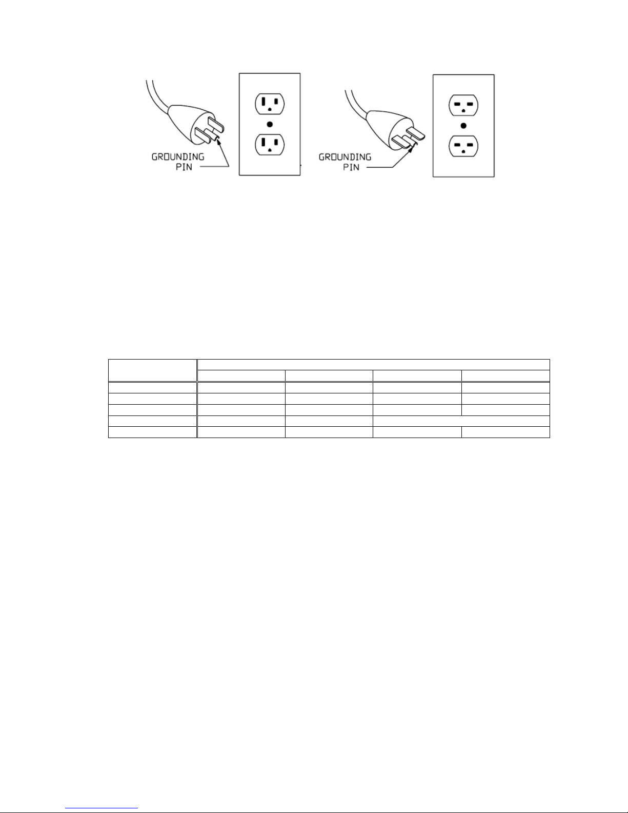
4) Inspect the power code and plug for damage. If the plug has been modified, is missing the
grounding pin, or if the cord is damaged, do not use the threading machine until the cord has been
replaced.
5) Inspect the threading machine for any broken, missing, misaligned parts as well as any other
conditions which may affect the safe and normal operation of the machine.
6) Lubricate the threading machine if necessary according to the Maintenance Instructions.
7) Use tools and accessories that are designed for your threading machine. The correct tools and
accessories allow you to do the ob successfully and safely.
8) Clean any oil, grease or dirt from all handles and controls. This reduces the risk of in ury due to a
tool or control slipping from your grip.
9) Inspect the cutting edges of your tools and dies. If necessary, replace them prior to using the
threading machine.
10) Clean metal shavings and other debris from Chip Tray of the threading machine. Check the level
and quality of the cutting oil. Replace or add oil if necessary. The suitable quantity is 80% of the
tank inside. Cutting oil lubricates and cools the threads during the threading operation. A dirty or
poor grade cutting oil can result in poor thread quality and reduce die life.
11) To drain dirty oil and replace the oil, refer to the Maintenance Instructions.
2. Machine and Work Area Se -Up
To prevent serious in ury, proper set-up of the machine and work area is required. The following
procedures should be completed.
1) Locate a work area properly by considering adequate lighting, eliminating flammable liquids,
vapors or dust
2) Make sure the grounded electrical outlet.
3) Clear path to the electrical outlet that does not contain any sources of heat or oil, sharp edges or
moving parts that may damage electrical cord.
4) Dry place for machine and operator. Do not use the machine while standing in water.
5) Make sure that the ground is even and has clean surface for stable mounting of machine.
6) Clean up the work area prior to setting up any equipment. Always wipe up any oil that may have
splashed or dripped from the machine to prevent slips and falls.
7) If the workpiece extends more than 1m beyond the threading machine, use one or more pipe
stands to prevent tipping and the oscillation of the pipe.
8) If the workpiece extends beyond the threading machine, set-up guards or barricades to avoid any
accident.
9) Make sure ON/OFF switch is in the OFF position.
10) Stand facing the machine.
11) Have convenient access to the ON/OFF switch, tools and chucks without reaching across the
machine. Machine is designed for one person operation.

9
WARNING
WARNINGWARNING
WARNING: Keep all electrical connections dry and off the ground. Do not touch plug with wet
hands. Otherwise, you can not avoid the risk of electrical shock.
WARNING: FIRST AID TREATMENT
If oil gets in eyes, wash them with pure water and see a doctor.
If oil sticks to skin, wash well with water and soap.
If swallowed, do not induce vomiting and see a doctor.
If inhaled mist, move to the clean place, cover with blanket, keep warm and quiet
and see a doctor.
12) Plug the threading machine into the electrical outlet making sure to position the power cord along
the clear path selected earlier. If the power cord does not reach the outlet, use an extension cord
in good condition.
13) To avoid electrical shock and electrical fires, never use an extension cord and understand the
“Electrical safety” in “Safety Information” well
14) Check the threading machine to insure it is operating properly.
15) Turn the switch on and check that the threading machine rotates in a designated direction.
16) Inspect the moving parts for misalignment, binding, odd noises or any other unusual conditions
that may affect the safe and normal operation of the machine. If such conditions are present, have
the machine serviced.
17) Turn the switch off.
3. Cu ing Oil Lubrica ion
Use genuine MCC Cu ing Oil.
MCC cu ing oil Improves he finished screw surfaces and ex ends Die's service life.
MCC Cu ing Oil is sui able for wa er works pipe for easy washing.
1) Remove Chip Tray from oil tank.
[NOTE]
Remove foreign subs ance from oil ank.
Change he whole oil if rain urns he oil cloudy or dir y.
2) Fill the tank 80% full with the cutting oil.
3) Reinstall Chip Tray.
STORAGE
Store machine in a place inaccessible to children and out of the way of people. This is chemical product.
Never leave machine in an area exposed to direct sunlight. Always store it in a cool, dark location. Make
sure that Punching Plate is tightly in place and the machine is covered when not in use to avoid
contamination (e.g. dust and moisture).

10
WARNING: * Always read and follow "Safety Information" and "Preparing for Operation"
* SHARP! Do not touch cutting edges.
* Moving Parts! Keep hands and face away from moving blades and parts.
Moving parts could pull in ob ects such as clothing, hair, ewelry and fingers.
* If there is a problem or malfunction, IMMEDIATLEY stop the machine and
disconnect the power cord.
* Always remove the chip and keep machine clean before and after operation.
* After operation, switch off and disconnect Power Cord.
Failure to follow these instructions could result
i
n
s
erious
p
ersonal
i
n ury.
NOTE:
* For longer lifetime of motor, please avoid continued threading operation more than 30
minutes.
* Use low or high speed as listed in Name Plate based on pipe and size. Higher speed than
listed may cause a damage on motor.
Machine Opera ion
1. Elec rical Requiremen
1) Make sure to adequately ground the machine prior to operation.
2) If an extension power cord is required, make sure to use the appropriate cable listed in the chart in the
page No. 4 in this manual to prevent drop of voltage which damage motor.
2. To Replace Dies
NOTE: First, be sure to unplug the power cable.
1) Loosen Hex Nut which is located behind Die Head.
2) Insert
Release Bar
(small end)
into the hall on
Die
Head. Turn Die Head to the direction indicated in the
photo all the way. Then, slightly tighten Hex Nut to hold
the position.
3)
Turn
Cam Handle towards back until the slots for
Dies are lined up straight.

11
4) Remove all Dies. Now, ready for installing new Dies.
5) When installing new Dies, make sure that the
number on Dies (1 – 4) matches the same number on
Die Head. Then, insert Dies all the way.
6) Turn Cam Handle towards front all the way.
7)
Loosen
H
ex
N
ut
which is located behind Die Head.
8) Insert the Release Bar
(Small end)
into the hall on
Die Head. Then, turn it until the size indication and line
meets at the size that you cut the thread.
8)
Tighten
Hex N
ut
again.
3
.
To Replace Di
e Head
NOTE First, be sure to unplug the power cable.
1) Insert Release Bar(Large end) into the hall on Die
Head and turn Die Head to front.

12
2) Die Head can be removed.
3) Before attaching Die Head, clean up the surface of
Die Head where contacts the machine.
4)
Insert
Release Bar(Large end) into the hall on Die
Head and turn Die Head to back.
4. High Speed and Low Speed
1) MCC CM82 is equipped with two-speed transmission. The low speed
operation could be chosen by turning Change Lever to left from view of
operator’s side, and the high-speed operation by turning Change Lever to
right. Turning Change Lever should be done ust before the motor is stopped
or right after the switch is on. Do not operate Change Lever when the motor
runs at full speed, or when the motor runs with threading load. Tighten Wing
Nut of Change Lever to secure the position of Change Lever in place and
avoid any mis-operation of Change Lever by accident.
2) Always operate this machine at the suggested cutting speed for pipe size
as listed in Name Plate on gear box.
3) When thread needs to be cut more than 100mm in length on PF1-PF3
heavy conduit pipe or C63- C75 light conduit pipe, operate this machine
always at low-speed. Moreover, when the heavy conduit pipe to be cut more
than 100mm threads repeatedly is PF1.1/2-PF3, turn the machine off occasionally for the purpose of
preventing the motor from damage or burnt.
5. To Cu Thread
1) Make sure that Cam Handle is in close position. (; when
Cam Handle is located at top, it should be swung towards
you to close Cam Handle.)
2) Make sure that the size of die head is properly set for the
size of pipe to be cut a thread. Size Gauge must be lined up
with the engraved line on Cam Plate.
3) Set Length Indicator on Lever Bracket on Support Bar to
the desired length on Length Gauge of Main Body. Tighten
up Wing Screw of Lever Bracket to secure.
4) Bring Die Head by turning Feed Handle to the left end of

13
NOTE:
* Thread pitch becomes slightly larger when thread is more than 40mm in length. This is nature
of thread-cutting with this type of machine.
`
Support Bars, and at that position, chuck a pipe in Vise by touching the front side of Dies with the pipe
end.
5) Turn switch on. Cutting oil is supplied from die head when it‘s on.
6) Send Die Head by turning Feed Handle to push against a pipe to be cut. When a few threads are cut on
the pipe, relax your hands on Feed Handle.
7) When the desired length of thread is cut, Dies release the pipe automatically.
8) Turn switch off.
9) Return Die Head by turning Feed Handle to the left end, and release the pipe from Vise.
10) When thread needs more than 110mm in length, bring the Length Indicator to the right end, and follow
the above instructions 4 to 6 in this section. When thread is cut about 100mm length and before the pipe is
released from Dies, turn a switch off. Release the pipe from vise, and bring Die Head with the pipe to the
left end by turning Feed Handle. Chuck the pipe in Vise again, then, turn a switch on to cut the further
length of thread.
6. Cu ing Oil
1) MCC cutting oil is formulated to extend service life of Dies and
provide a finer finish of thread. Always make sure that cutting oil
supply is adequate. Insufficient oil supply to thread-cutting will
shorten Dies life, cause rough finishing of thread, and may cause
a damage on Oil Pump.
2) Chips and other dirt dropped down from the Chip Receiver
gather at Filter (I). Clean this filter occasionally to assure efficient
oil circulation.
3) Occasionally take out Chip Receiver and drain cutting oil from
oil tank. Then, remove all chips and other sludges from the bottom
of Oil Tank and clean Filter (II) at the lubrication pump inlet.
4) Do not use or leave the machine outdoor. If the machine is left
outdoor by accident and exposed to rain, water may enter and
exist in Oil tank. Be sure to drain all water prior to operation.
5) To increase the flow of cutting oil, tighten Oil Ad ustment Screw(; Cap Screw) located underneath Die
Head.
7. Main enance and Inspec ion
1) Daily care of this machine is vital to the efficient threading work and to
the machine service life. Remove all cutting chips from the machine, and
clean Feed Screw and Insert Jaws on Vise often.
2) Since Spindle Oilless Metal is made of special oil contained metal,
daily lubrication is no required. To insure long service life, lubricate it
every three to six months depending on use.
3) The support bar must be well lubricated to insure smooth operation.
Supply machine oil on support bars and slide them several times.
4) Replace Carbon Brushes with new ones after 250-300 hours use,
when about 2/3 of the carbon is worn out, it raise a risk to damage
Commutator of Motor.
5) Do not leave the machine outdoors. Rain might get into the motor and cause a damage.
8. Chamfering
1) Install Reamer(; optional accessory) in Drive Shaft from the motor
side by screwing it to left (see Fig).
2) After threading is done, slide Die Head back to a few centimeter left.
3) Loosen Vise and send the pipe into Drive Shaft until the pipe contact
Reamer. Then chuck the pipe in Vise again.
4) Turn the switch on and push Reamer against the pipe for chamfering.
5) To take Reamer off from Drive Shaft, insert Release Bar into a hole
on Reamer Shaft, then, rotate it to right.

14
Factory
MCC Corporation
1814 Takachaya Komoricho, Tsu City, Mie Pref., 514-0817, Japan
International sales
MCC International Inc.
Sanko Bldg. Room 507, 3-9, 1-Chome, Minamihonmachi,
Chuo-Ku, Osaka, 541-0054, Japan
Phone:81-6-6264-0361
Fax:81-6-6271-7798
info@mccinter.com
www.mccinter.com
Table of contents
Popular Tools manuals by other brands

GPI
GPI GL-332 Instructions for use

BorMann
BorMann BWR5037 operating instructions

Ingersoll-Rand
Ingersoll-Rand QA1L High Torque Series Operation and maintenance manual

Hilti
Hilti NPR 24-22 Original operating instructions

Vigor Equipment
Vigor Equipment V4416 Application note

Staubli
Staubli MA270 operating instructions