MCCI Catena 4610 User manual

MCCI Corporation
3520 Krums Corners Road
Ithaca, New York 14850 USA
Phone +1-607-277-1029
Fax +1-607-277-6844
www.mcci.com
Catena 4610 User Manual
Engineering Report 234001177
Rev B
Date: 2019-09-09
Copyright © 2019
All Rights Reserved

Catena 4610 User Manual
Engineering Report 234001177 Rev B
- ii -
PROPRIETARY NOTICE AND DISCLAIMER
Unless noted otherwise, this document and the information herein disclosed are proprietary to MCCI
Corporation, 3520 Krums Corners Road, Ithaca, New York 14850 (“MCCI”). Any person or entity to
whom this document is furnished or having possession thereof, by acceptance, assumes custody thereof
and agrees that the document is given in confidence and will not be copied or reproduced in whole or in
part, nor used or revealed to any person in any manner except to meet the purposes for which it was
delivered. Additional rights and obligations regarding this document and its contents may be defined by
a separate written agreement with MCCI, and if so, such separate written agreement shall be controlling.
The information in this document is subject to change without notice, and should not be construed as a
commitment by MCCI. Although MCCI will make every effort to inform users of substantive errors, MCCI
disclaims all liability for any loss or damage resulting from the use of this manual or any software
described herein, including without limitation contingent, special, or incidental liability.
MCCI, TrueCard, TrueTask, MCCI Catena, and MCCI USB DataPump are registered trademarks of MCCI
Corporation.
MCCI Instant RS-232, MCCI Wombat and InstallRight Pro are trademarks of MCCI Corporation.
All other trademarks and registered trademarks are owned by the respective holders of the trademarks
or registered trademarks.
Copyright © 2019 by MCCI Corporation.
Document Release History
Rev A
2019-03-01
Initial Release
Rev B
2019-09-09
Updated the User Manual

Catena 4610 User Manual
Engineering Report 234001177 Rev B
- iii -
TABLE OF CONTENTS
1 Introduction .......................................................................................................................................... 5
2 Specifications and Features .................................................................................................................. 5
2.1 Additional Features....................................................................................................................... 6
3 Catena 4610 Pinouts ............................................................................................................................. 7
3.1 Logic Pins....................................................................................................................................... 8
3.1.1 Connector JP1 ....................................................................................................................... 8
3.1.2 Connector JP3 ....................................................................................................................... 9
3.1.3 Connector JP4 & JP5 ............................................................................................................. 9
3.2 Power Pin .................................................................................................................................... 10
3.3 Other Pins....................................................................................................................................10
4 Power Source ......................................................................................................................................11
5 Antenna Options ................................................................................................................................. 11
5.1 Whip Antenna ............................................................................................................................. 11
5.2 U.FL .............................................................................................................................................12
5.3 SMA............................................................................................................................................. 13
6 Additional Accessories ........................................................................................................................14
6.1 Programming Requirements....................................................................................................... 14
6.1.1 ST-LINK/V2 in-circuit debugger/programmer..................................................................... 14
6.1.2 USB to Serial Cable..............................................................................................................14
7 Software Requirements ......................................................................................................................15
8 Assembly Instructions......................................................................................................................... 15
9 Configurations of Catena 4610 ........................................................................................................... 17
9.1 Library Installation ......................................................................................................................17
9.2 Arduino IDE Setup.......................................................................................................................18
9.3 Programming Methods ...............................................................................................................21
9.3.1 ST-LinK................................................................................................................................. 21
9.3.2 DFU...................................................................................................................................... 24
9.4 Provisioning Steps....................................................................................................................... 26
9.5 TTN Registration Steps................................................................................................................ 26

Catena 4610 User Manual
Engineering Report 234001177 Rev B
- iv -
LIST OF TABLES
Table 1 Antenna Specification .................................................................................................................... 12
Table 2 USB to Serial Connection................................................................................................................ 17
Table 3 Catena 4610 to STLink connection.................................................................................................22
LIST OF FIGURES
Figure 1 Catena 4610 .................................................................................................................................... 5
Figure 2 Catena 4610 Description................................................................................................................. 6
Figure 3 Catena 4610 Pinout......................................................................................................................... 8
Figure 4 Whip Antenna ............................................................................................................................... 11
Figure 5 uFL antenna................................................................................................................................... 12
Figure 6 uFL/SMA adapter cable................................................................................................................. 13
Figure 7 SMA antenna................................................................................................................................. 13
Figure 8 ST Link Programmer ......................................................................................................................14
Figure 9 USB to Serial Cable........................................................................................................................15
Figure 10 Catena 4610 after soldering components .................................................................................. 16
Figure 11 Catena 4610 with Battery ...........................................................................................................16
Figure 12 Catena 4610 Serial Configuration ............................................................................................... 17
Figure 13 Cloning libraries using the script.................................................................................................18
Figure 14 BSP Search................................................................................................................................... 19
Figure 15 BSP Installation ........................................................................................................................... 20
Figure 16 BSP Installed................................................................................................................................ 20
Figure 17 Selection of device from list of boards .......................................................................................21
Figure 18 Catena 4610 connection with PC using STLink Debugger.......................................................... 22
Figure 19 Catena 4610 connection with ST Link programmer.................................................................... 23
Figure 20 Configuration for upload using STLink programmer................................................................... 23
Figure 21 Catena 4610 DFU Mode Connection........................................................................................... 24
Figure 22 Zadig Device Selection ................................................................................................................ 24
Figure 23 Zadig driver replacement............................................................................................................25
Figure 24 Configuration for upload using DFU mode ................................................................................. 25
LIST OF SEQUENCE DIAGRAMS
No table of figures entries found.

Catena 4610 User Manual
Engineering Report 234001177 Rev B
- 5 -
1Introduction
The MCCI Catena® 4610 is a complete single-board IoT device for LoRaWAN™ technology
projects.
Based on the Murata CMWX1ZZABZ-078, and designed to be compatible with the Adafruit
Feather family of development boards and accessories, the Catena 4610 is a great platform for
LoRaWAN investigation and deployment. It works well with The Things Network, or any
LoRaWAN 1.0 or 1.1 network in the 865 to 923 MHz range.
Lightweight and small (roughly 2" by 0.9"), the 4610 needs no external components to measure
and send temperature, pressure, humidity, and lux, powered from USB or any Feather-
compatible LiPo (Lithium-Polymer) battery.
Because of the embedded FRAM, the Catena 4610 fully meets the requirements of LoRaWAN
1.1, without worrying about EEPROM wearout or wear-leveling, both for ABP and OTAA.
Figure 1 Catena 4610
2Specifications and Features
The specifications and features of Catena 4610 is given below:
Murata LoRaWAN module

Catena 4610 User Manual
Engineering Report 234001177 Rev B
- 6 -
Semtech SX1276 LoRa radio
STM32L082 CPU (Cortex M0+, 32 MHz, 192K flash, 20K RAM)
High quality RF engineering
Certified for US and EU
Compatible with IN866, AS923, AU921 bands
Figure 2 Catena 4610 Description
Integrated sensors
Pressure
Temperature
Humidity
Light
2.1 Additional Features
Powered from secondary 4V LiPo batteries (such as Adafruit's 350 mAh battery) (Note: in
contrast to the Catena 4612, this model targets LiPo batteries only. If you need
primary/disposable batteries, please consider the 4612).
100uA current draw in stand by
8K bytes FRAM for LoRaWAN provisioning info and frame counters -- power can be removed
completely without requiring a new join to the network, and without losing uplink and downlink
count values (required for LoRaWAN 1.1)
1M byte SPI Flash for bulk data storage, future FoTA firmware storage, etc.

Catena 4610 User Manual
Engineering Report 234001177 Rev B
- 7 -
Software-controlled boost converter allows dynamically raising voltage to 3.3V for analog
measurement and powering internal sensors
USB or SWD for download and debug
Pin-compatible with Adafruit Feather M0 family of boards (some limitations because the of
functional differences between the Murata module and the Atmel SAMD21 CPU used in the
Feather M0)
Arduino-compatible
Compatible with the MCCI Catena 4450 and Catena 4612 IoT devices
Designed for use with The Things Network (open-source, user-owned IoT network based on
LoRaWAN); but can be used with any LoRaWAN-compatible network
Provisions for screw terminals for pulse, analog or digital I/O
Software-controlled switches for external power output to screw terminals
Whip, u.FL, or SMA antenna
Open source hardware and software (https://github.com/mcci-catena)
MCCI provides a full Arduino board-support package, available here.
MCCI also provides libraries to allow rapid prototyping and experimenting, including an open-
source LoRaWAN stack that supports the EU868, US915, AS923, AU921 and IN866 regional plans.
ST Micro tools may also be used.
The Catena 4610 works well with and is tested with The Things Network (an open-source, user-
owned IoT network based on LoRaWAN); but can be used with any LoRaWAN-compatible
network.
3Catena 4610 Pinouts
Catena 4610 Pinout is given below:
Catena 4610 User Manual
Engineering Report 234001177 Rev B
- 8 -
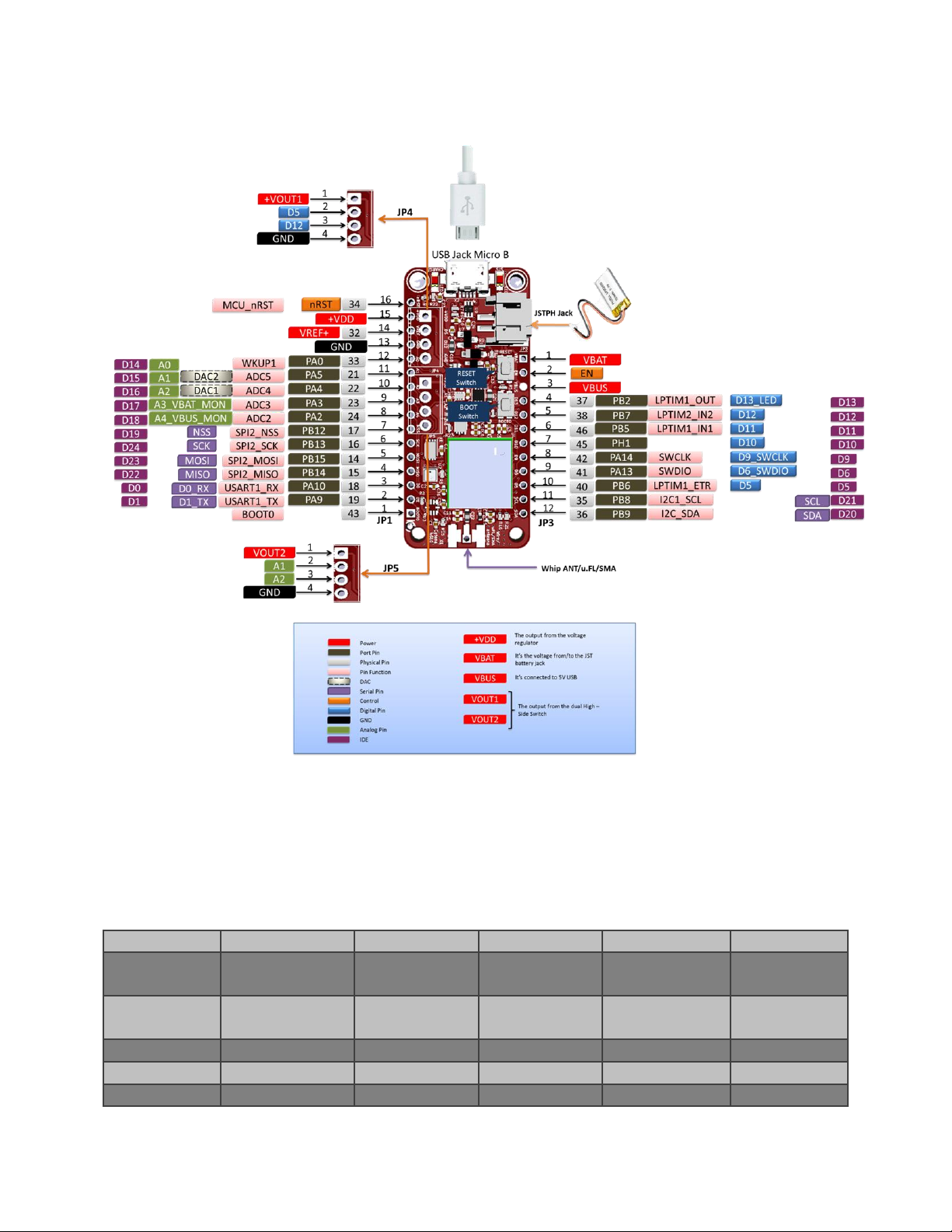
Figure 3 Catena 4610 Pinout
3.1 Logic Pins
3.1.1 Connector JP1
JP1 is a 16 pin connector which has General Purpose I/O pin.
PIN #
Pin Function
Analog Pin
Digital Pin
Purpose
Description
2
USART1_TX
D1
D1_TX
Transmit pin
for Serial1
3
USART1_RX
D0
D0_RX
Receive pin
for Serial1
4
SPI2_MISO
D22
MISO
5
SPI2_MOSI
D23
MOSI
6
SPI2_SCK
D24
SCK

Catena 4610 User Manual
Engineering Report 234001177 Rev B
- 9 -
7
SPI2_NSS
D19
NSS
8
ADC2
A4
D18
A4_VBUS_MON
Used to
Monitor the
VBUS
9
ADC3
A3
D17
A3_VBAT_MON
Used to
Monitor the
Battery
Voltage(VBAT)
10
ADC4/DAC1
A2
D16
A2
GPIO
11
ADC5/DAC2
A1
D15
A1
GPIO
12
A0
D14
A0
GPIO
3.1.2 Connector JP3
PIN #
Pin Function
Analog Pin
Digital Pin
Purpose
Description
4
LPTIM1_OUT
D13
D13_LED
Status LED
5
LPTIM2_OUT
D12
D12
GPIO
6
LPTIM1_IN
D11
D11
7
D10
8
SWCLK
D9
D9_SWCLK
Used for the
purpose of
programming
the board
using ST-Link
Programmer
9
SWDIO
D6
D6_SWDIO
Used for the
purpose of
programming
the board
using ST-Link
programmer
10
LPTIM1_ETR
D5
D5
11
I2C1_SCL
SCL
I2C Clock pin
12
I2C1_SDA
SDA
I2C Data pin
3.1.3 Connector JP4 & JP5
In JP4 and JP5, screw terminals can be connected. These connectors have GPIO pins with a power pin
(VOUT1, VOUT2) and GND. These pins can be used for the customized usage by the user.
Connector
Pin
JP4
D4, D12
JP5
A1,A2
Catena 4610 User Manual
Engineering Report 234001177 Rev B
- 10 -
3.2 Power Pin
PIN #
Connector Ref #
Pin Function
Description
14
JP1
VREF+
Reference
Voltage same as
the logic Voltage
(3.3V)
15
JP1
VDD
The output from
the voltage
regulator
3
JP3
VBUS
5V comes from
USB
1
JP3
VBAT
Voltage from the
battery
1
JP4
VOUT1
Output voltage
from the Dual
High Side Switch
1
JP5
VOUT2
Output voltage
from the Dual
High Side Switch
3.3 Other Pins
PIN #
Connector Ref #
Pin Function
Description
1
JP1
BOOT0
Boot Pin –Helps
to send the board
in Boot mode
(enumerate as
Bootloader) for
programming
16
JP1
nRST
Reset pin –Helps
to reset the
board.
2
JP3
EN
To enable the
3.3V voltage
regulator
Catena 4610 User Manual
Engineering Report 234001177 Rev B
- 11 -
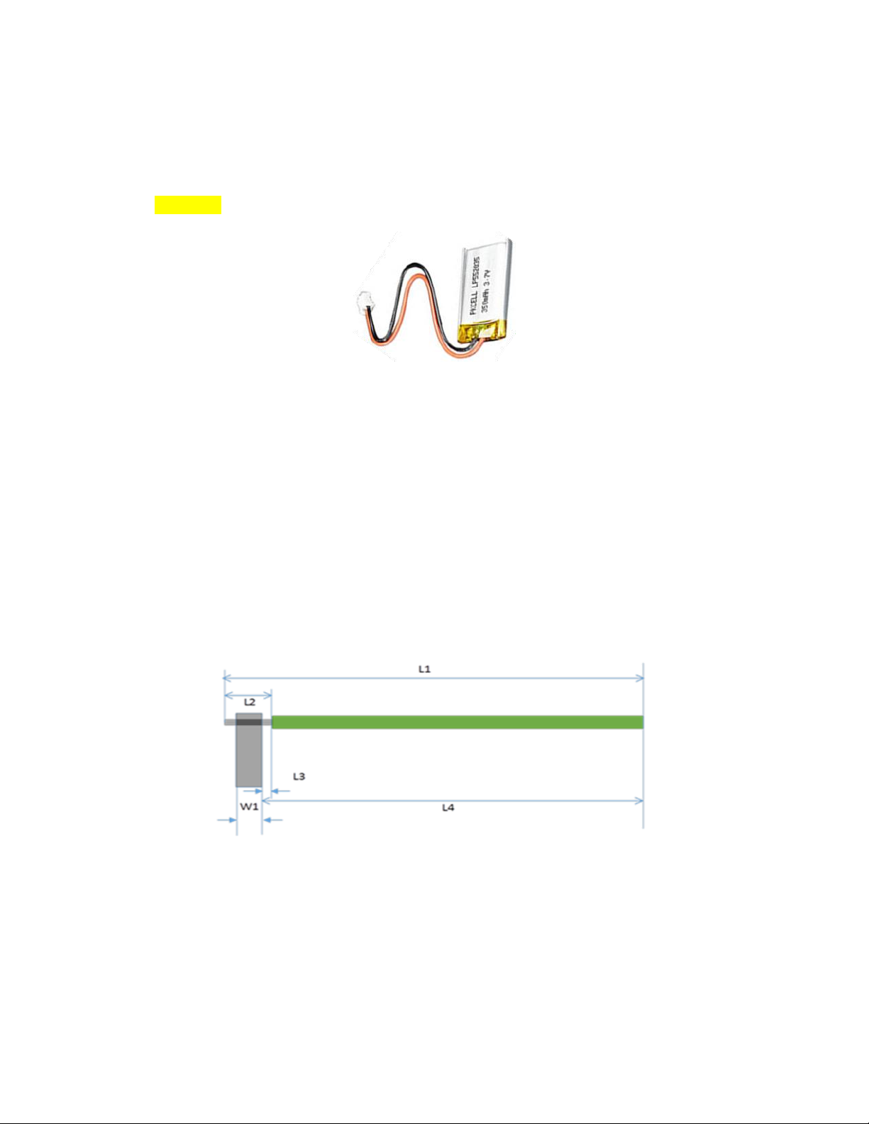
4Power Source
Any power source which provides 3.3V can be used to power Catena –4610.
In our application, we can use a Lithium polymer battery. Red Wire of the battery to the Power Supply
and the Black wire to the Ground
5Antenna Options
Catena devices to communicate over network, any of the following three Antennas can be used.
Whip Antenna
u.FL
SMA
5.1 Whip Antenna
The antenna specifications are shown in Table 1
Figure 4 Whip Antenna
Catena 4610 User Manual
Engineering Report 234001177 Rev B
- 12 -
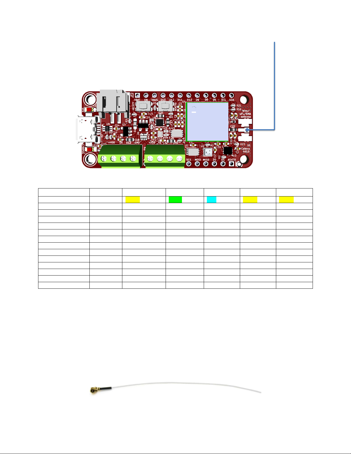
Table 1 Antenna Specification
Parameters
Reference
US Version
EU Version
IN Version
AU Version
AS Version
Wire Color
Yellow
Green
Blue
Yellow
Yellow
Reference Number
123001007
123001069
123001070
123001007
123001007
Wire length
L1
88.6
84.2
88.9
82
82
Tolerance
-
+/- 0.3 mm
+/- 0.3 mm
+/- 0.3 mm
+/- 0.3 mm
+/- 0.3 mm
Board thickness
W1
1.5748
1.5748
1.5748
1.5748
1.5748
Tin length
L2
3 mm
3 mm
3 mm
3 mm
3 mm
Tin tolerance
-
+/- 0.03 mm
+/- 0.03 mm
+/- 0.03 mm
+/- 0.03 mm
+/- 0.03 mm
Slop from soldering
L3
1.5 mm
1.5 mm
1.5 mm
1.5 mm
1.5 mm
Minimum length
-
80.9
80.9
85.6
80.9
80.9
Maximum length
-
82.9
82.9
86.6
82.9
82.9
Typical length
L4
81.9
81.9
87.6
81.9
81.9
Minimum f
-
903.83 MHz
903.83 MHz
855.33 MHz
915 MHz
920 MHz
Maximum f
-
928.80 MHz
928.80 MHz
875.87 MHz
928 MHz
925 MHz
Typical f
-
915 MHz
915 MHz
866 MHz
921 MHz
923 MHz
5.2 U.FL
If wants to use u.FL antenna, then have to install u.FL SMT Connector in the board as in Error! Reference
source not found.. Then connects the u.FL antenna to the board.
NOTE: User can also connect an SMA antenna with the help of u.FL/SMA adapter cable.
Figure 5 uFL antenna

Catena 4610 User Manual
Engineering Report 234001177 Rev B
- 13 -
Figure 6 uFL/SMA adapter cable
5.3 SMA
If the user wants to install an SMA connector to the Catena board to use SMA antenna. Then install the
SMA connector as shown in Error! Reference source not found.
Figure 7 SMA antenna

Catena 4610 User Manual
Engineering Report 234001177 Rev B
- 14 -
6Additional Accessories
Catena 4610 can also have some of the optional accessories for their connectors to have easy interface.
6.1 Programming Requirements
6.1.1 ST-LINK/V2 in-circuit debugger/programmer
The ST-LINK/V2 (123001120) is an in-circuit debugger and programmer for the STM8 and STM32
microcontroller families. The single wire interface module (SWIM) and JTAG/serial wire debugging (SWD)
interfaces are used to communicate with any STM8 or STM32 microcontroller located on an application
board.
Figure 8 ST Link Programmer
6.1.2 USB to Serial Cable
USB to Serial Cable (123001121) is used for Configuring the device with TTN and also for
monitoring the device performance on the Serial Monitor.

Catena 4610 User Manual
Engineering Report 234001177 Rev B
- 15 -
Figure 9 USB to Serial Cable
Note: The Serial cable configurations are mentioned in the Table 2
7Software Requirements
To proceed with Catena 4610 setup and test procedure, the below software tools are required.
Arduino IDE for windows can be downloaded from below link:
ohttps://www.arduino.cc/en/Main/Software
ST-Link Debugger driver for windows can be downloaded from the link below:
ohttps://www.st.com/en/development-tools/st-link-v2.html
USB to Serial converter for windows
Zadig tool is required for programming Catena 4610 the tool can be downloaded from the link
below:
ohttps://zadig.akeo.ie
Catena-Sketches for examples of all Catena devices (catena4612_simple.ino and
catena461x_test01.ino can be used for Catena 4610). Use command “git clone
https://github.com/mcci-catena/Catena-Sketches.git” to clone Catena Sketches.
Basic libraries required
oCatena-Arduino-Platform
oCatena-mcciadk
oarduino-lorawan
oarduino-lmic
oAdafruit_BME280_Library
oAdafruit_FRAM_I2C
oAdafruit_Sensor
8Assembly Instructions
1) Catena 4610 board assembling procedures are listed below:
a. Attach the Error! Reference source not found. on JP1 and JP2 of Catena 4610 board
respectively.
Catena 4610 User Manual
Engineering Report 234001177 Rev B
- 16 -
i. Solder one or two posts on each strip, to tack the header in place
ii. Adjust the vertical and horizontal alignment
iii. Solder the remaining posts for reliable electrical contact
b. Trim excess length of the 16-pin header in the area of screw terminals.
c. Solder the Whip antenna as per the Antenna Specification mentioned in Table 1.
d. Attach the Error! Reference source not found. on JP3 and JP4 respectively.
i. Solder one post
ii. Adjust for proper alignment and good cosmetics
iii. Solder the remaining posts
NOTE: Catena 4610 Base do not require male pin headers and screw terminals to be soldered (only
whip antenna is sufficient for base board). However, user can solder them based on their setup
requirement.
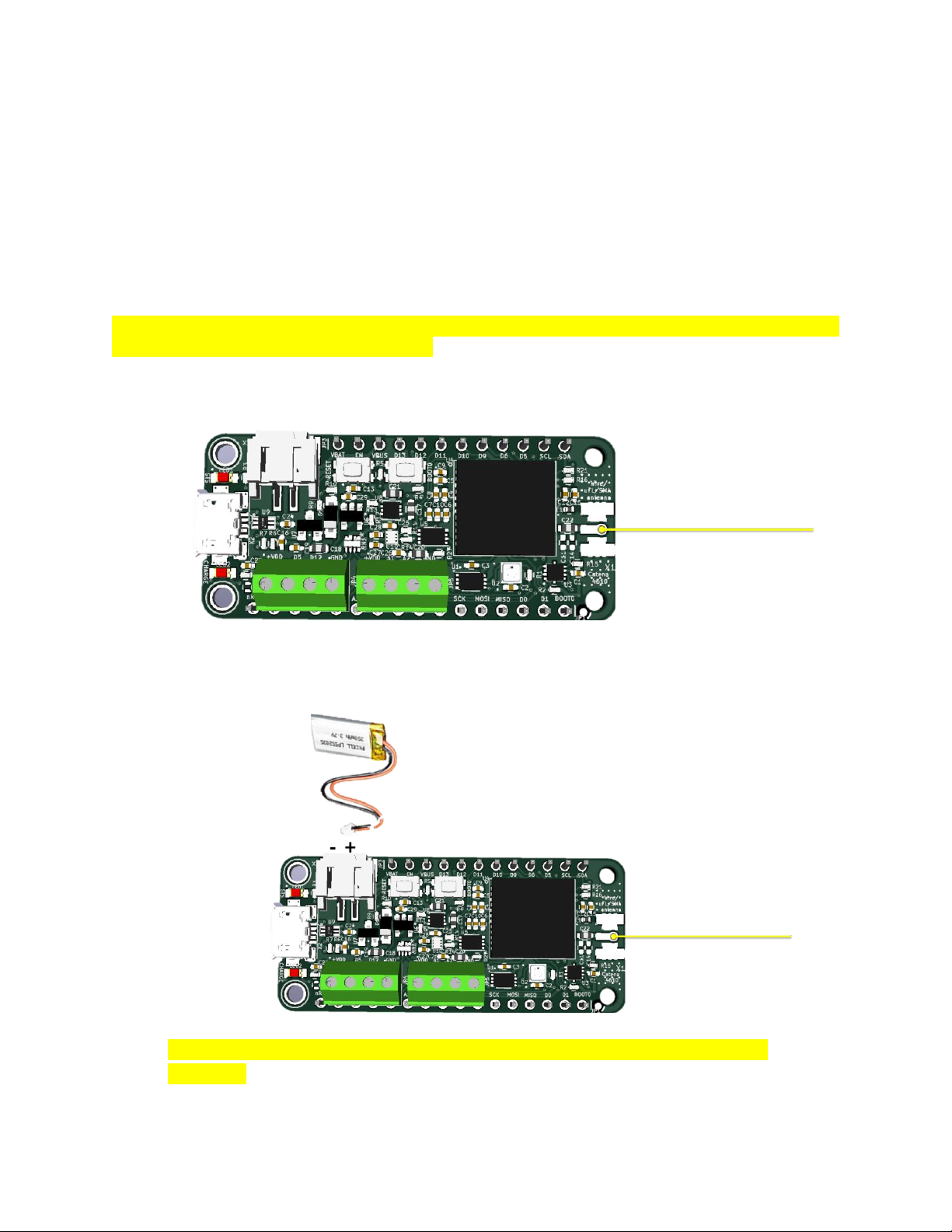
Figure 10 Catena 4610 after soldering components
e. Connect the Battery to the X3 of the board.
Figure 11 Catena 4610 with Battery
(Note: The orange plastic seal from the BME–280 (U1) should be removed for proper
operation. This seal is intended for protection during manufacturing)

Catena 4610 User Manual
Engineering Report 234001177 Rev B
- 17 -
2) Catena 4610 Serial connection.
User can prefer Generic Serial for Serial Interface when USB cable is not used in the setup.
MCCI preferred using USB to Serial Cable TTL-232R-RPI and it has been used for Serial
monitor. The color code and the pin configuration detail are listed in the Table 2
Figure 12 Catena 4610 Serial Configuration
Table 2 USB to Serial Connection
Catena4610 (JP1)
USB - Serial cable (color)
GND
Black
D0_RX
Orange
D1_TX
Yellow
9Configurations of Catena 4610
9.1 Library Installation
Catena 4610 simple sketch requires the following libraries:
Catena-Arduino-Platform
Catena-mcciadk
arduino-lorawan
arduino-lmic
Adafruit_BME280_Library

Catena 4610 User Manual
Engineering Report 234001177 Rev B
- 18 -
Adafruit_FRAM_I2C
Adafruit_Sensor
The above libraries can be cloned from https://github.com/mcci-catena or by executing the shell script
“git-boot.sh” in the directory.
It's easy to run, provided you're on Windows, macOS, or Linux, and provided you have git installed. We
tested on Windows with git bash from https://git-scm.org, on macOS 10.11.3 with the git and bash
shipped by Apple, and on Ubuntu 16.0.4 LTS (64-bit) with the built-in bash and git from apt-get install git.
Refer the Figure 13 to clone using the script git-boot.sh.
Figure 13 Cloning libraries using the script
9.2 Arduino IDE Setup
Now follow the below steps to upload the test sketch using Arduino IDE:
1. Open the example catena4612_simple in Arduino IDE. Go to File>Preferences>Settings. Add
Catena 4610 User Manual
Engineering Report 234001177 Rev B
- 19 -
“https://github.com/mcci-catena/arduino-
boards/raw/master/BoardManagerFiles/package_mcci_index.json”
to the list in Additional Boards Manager URLs.
2. If you already have entries in that list, use a comma (,) to separate the entry you're adding from
the entries that are already there.
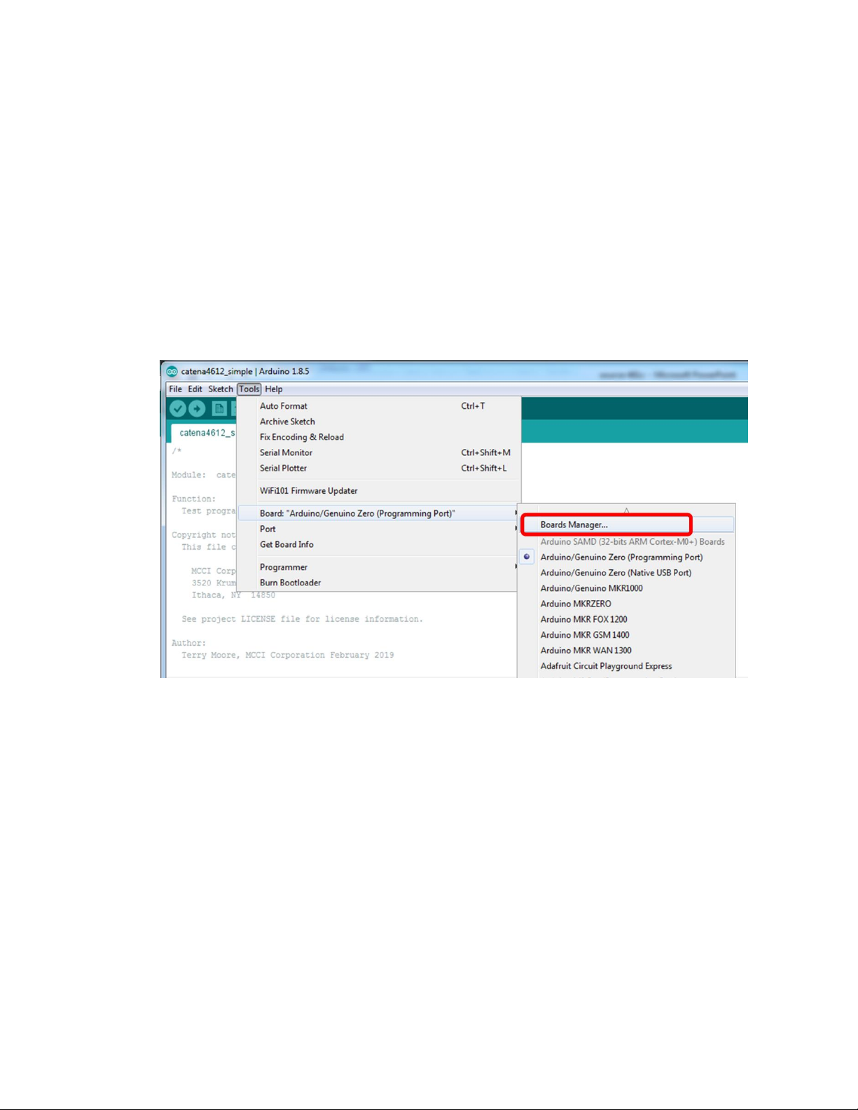
3. Next, open the board manager. Tools>Board:...Search for MCCI’s BSPs
4. Install the latest BSP for MCCI Catena STM32 to add support for Catena 4610 in Arduino IDE.
5. MCCI Catena STM32 Boards should be installed from the Boards Manager.
6. Once the board has been installed, Catena 4610 board has to be selected under MCCI Catena
STM32 Boards.
Figure 14 BSP Search
Catena 4610 User Manual
Engineering Report 234001177 Rev B
- 20 -
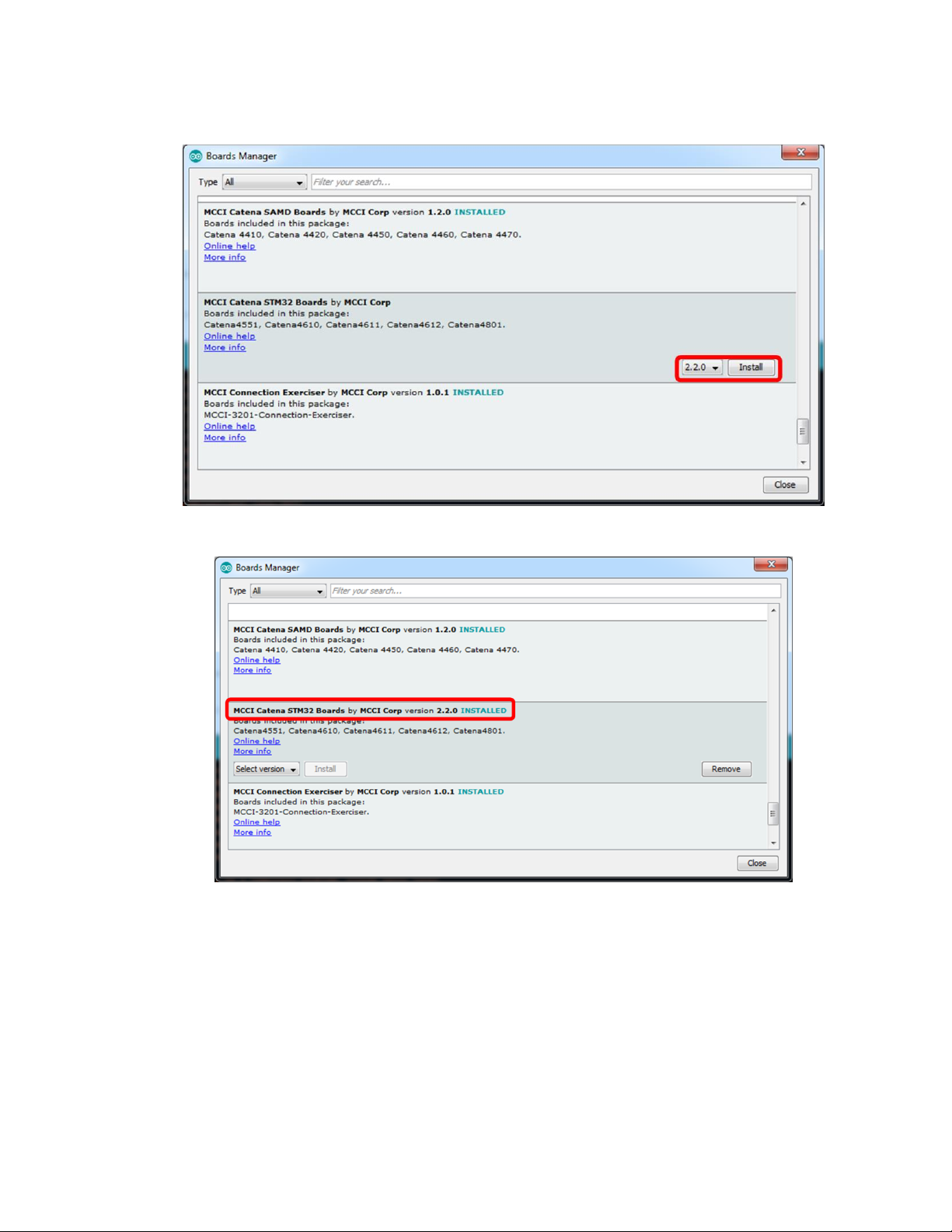
Figure 15 BSP Installation
Figure 16 BSP Installed
Table of contents
Other MCCI Network Hardware manuals

Popular Network Hardware manuals by other brands


evertz
evertz 5600ACO instruction manual

Altronix
Altronix NetWay NetWay112 installation guide

Delight Power Products Limited
Delight Power Products Limited WB14 quick start guide

hilscher
hilscher NXHX 52-JTAG Getting started

HFX
HFX PowerNAS 2011 user manual

Trend Micro
Trend Micro InterScan Web Security Appliance 2500 quick start guide


