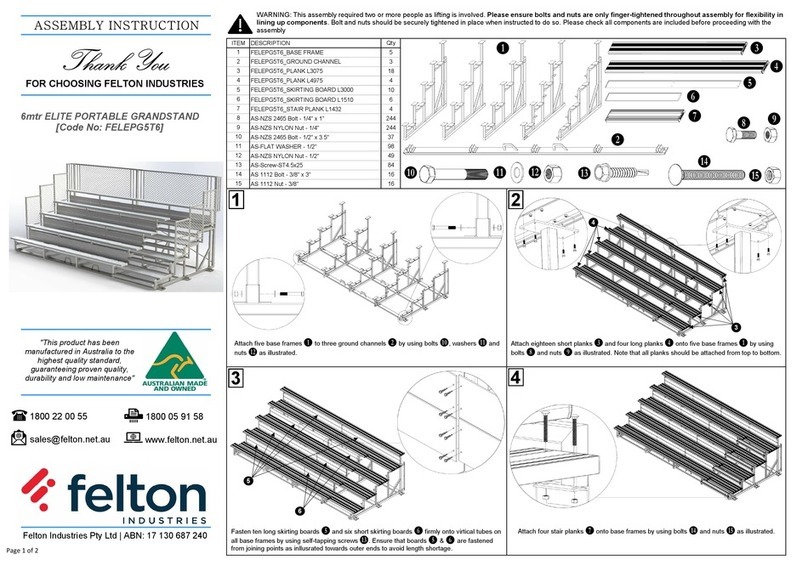
McCue CartPark Architectural User manual

mccue.com
4 BARRIER INSTALLATION INSTRUCTIONS
Questions? Call McCue Customer Care at 800.800.8503
©2013 McCue Corporation, 13 Centennial Drive, Peabody, MA 01960, USA. MAR 2014
CartPark
Architectural
1
2
4
5
10
1111
5
15
14
10
12
Bill Of Materials
CARTPARK ARCHITECTURAL
ITEM #
QTY DESCRIPTION McCUE DRAWING
OR PART #
1 1 Rear Left Vertical Post, 83.25” LONG CCASFABVPRL
2 1 Rear Right Vertical Post, 83.25” LONG CCASFABVPRR
3 2 Front Vertical Post, 83.25” LONG CCASFABVPF
4 2 Lower Side Rail, Barrier Connector 135.4375” LONG CCASFABLSR
5 2 Upper Side Rail, Guidance Rail Notched 135.4375” LONG CCASFABUSR
6 1 Back Stop Bar, 95.1875” LONG CCASFABBR
7 1 Top Rail Left, Horizontal Bar, 164.0” LONG CCASFABTRL
8 1 Top Rail Right, Horizontal Bar, 164.0” LONG CCASFABTRR
9 2 Crossbar Along Top, 96.875” LONG CCPASFABCR
10 2 Roof Frame Assembly, 164” x 56.0” x 2.0” FRAME CCPASFABRF
4 Roof Slope, 53.6875” LONG CCPASFABRS
4 End Roof Slope with Tri-Glass Panel Mounting Holes CCPASFABRSE
2 Top Ridge, with Weather Foam Tape, 164” LONG CCPASFABRDG
2 Bottom Sill, 164” LONG CCPASFABSILL
6
Roof Cross Member, with Double Sided Tape 52.75” LONG
CCASFABCM
ITEM #
QTY DESCRIPTION McCUE DRAWING
OR PART #
11 6
Roof Panels, Acrylic Solid Sheet, 55.125” x 53.75” x .177”
CPAS-RFPNL
12 2 Retainer, Roof Drip Edge, 164.0” LONG CCASFABRET
13 4 Plastic Barrier, HDPE, 70.25” x 12.0” x 20.0” CCPAS-BARRIER-XXX
14 2 Tri-Glass Panel, High Impact Acrylic, 100.875” x 28.3”
x .236”
CCPAS-TRIPNL
15 2 Tri-Glass Panel Aluminum Support, 88.98”x.75”x.50” CCPASFABTPNLSP
CCPAS HARDWARE
ITEM #
QTY DESCRIPTION
130 ¼-20 x 1.0” Torx Pan Head Screw, Taptite 2000, S/S
7 ¼-20 x 1¾” Hex Washer Head Screw, S/S
7 ¼-20 Serrated Washer Nut, S/S
14 ¼-20x¾” Torx Pan Head, Self Tapping Screw, S/S
12 ¼-20x 2.0” Pan Head Torx
20 Aluminum Shoulder Spacer ¼” ID x ⅜” LONG
4 #10-32 x ⅜” Long #2 Drive, Thread Cutting Screw S/S

CartPark Architectural | Page 2 of 11
Tools Required.
2, Six foot step ladders
Tape Measure
Cordless Impact Driver
& back-up batteries
7/16” hex head driver bit
T30 Torx Bit
Tin shear
Hammer
Pry bar and Nail Puller
for wood crate
Cleaning Rags
1,200 pounds (544 kilograms)
of sand, pea stone or gravel
for ballasting
Screw wax .85oz (included)
Important: Assemble on a flat, level surface. All cart corrals should be inspected on a regular basis for
damage. McCue recommends a minimum of two inspections per year in the spring and fall. Any damaged
pieces should be replaced with McCue replacement parts.
2042mm
2032mm
ID
104.0
2642mm
712mm
164.00in
4166mm
20.00in
2750mm

CartPark Architectural | Page 3 of 11
2
Assemble right and left side frames
On a flat surface, set the back right vertical post, front vertical,
lower side rail and upper side rail as shown. Slide upper side
rail so that the notch is facing up and into the back right post
as shown in detail A.
Secure both lower and upper side rail to vertical posts with
14, Taptite ¼-20 x 1.0” screws coated with wax at the front and
back of the vertical posts. Do not over-tighten the screws.
Repeat this step to assemble the left side. Pieces should be
protected from scratches during the installation process.
1
Back Right
Front
Bottom Siderail
Notch Cut
Back Right
Back Left
Stopbar
Opening
Stand sides upright
When both left and right side frames are complete, stand sides
frame upright making sure that the cut out openings for the
stopbar are facing each other on the right and left back vertical
posts. The stopbar openings should be located towards the
back of the unit.

CartPark Architectural | Page 4 of 11
3Secure back stopbar
Slide the stopbar into the back left and right vertical
posts openings as shown. Orient back stopbar notches
to face down prior to sliding into vertical post. Secure
Stopbar to right and left vertical post with 4, Taptite
¼-20 x 1.0” screws coated with wax from the outside
of the unit. Do not over-tighten screws.
4
Stopbar
Notch Cut
Overhang
Left Top Rail
Cut out opening
Slide Left Top Rail into
left vertical uprights
Slide Left Top Rail into left frame vertical uprights so
that the overhang leans toward the front of the unit.
Cut out openings should face inside the unit.

CartPark Architectural | Page 5 of 11
5Slide Top Cross Rail
Slide cross rail into the cut out openings of the Left Top
Rail, outs as shown. Rest opposite end of cross rails into
the top of the right verticals. Do not secure crossbar and
continue next step.
6
Cross Rail
Cross Rail
Cut out Opening
Rest
Right Top Rail
upright
Secure Toprails
1
2
3
4
Cross Rail
Cross Rail
Secure Toprails
Secure Cross Rail
Open end of
Cross rail
Slide Right Toprail into Cross Rails
and into the right vertical uprights.
1. Slide right Toprail into the open ends of the crossbars.
2. Once in place, lift Toprail up and over uprights so that
the cross rails come off the uprights.
3. Slide top rail over uprights and
4. Lower into the open ends of the uprights. Secure
Toprails to uprights with 16, ¼-20 x 1.0” Taptite screws
coated with wax. Secure Cross rails to Right and Left
Toprails with 16, Taptite ¼-20 x 1.0” screws.
Important: Make sure every hole
attachment is secured by a screw.
A total of 32 screws are needed in
this step.

CartPark Architectural | Page 6 of 11
7Lift Roof Frame Assemblies and position
Lift both roof frame assemblies onto the top of the unit as shown so that
the outside edges run parallel to both horizontals. Make sure that the
roof panel groove is on the upper side and that the top ridge extrusions
are at the center of unit as shown in detail C. The front and back of the
roof assemblies should be flush with front of horizontals.
8
0.66in
17mm
Ridge
Top Ridge
Roof panel Groove
Right
Toprail
Left
Toprail
Flush
Temporary secure roof frame assemblies
to Right and Left Toprails.
Secure the outside edges of the roof frame assemblies to the Left Toprail
and Right Toprail at three of the holes with 3, Taptite ¼-20 x 1.0” screws
wax coated per side. Do not fully secure screws to allow roof frames
assemblies to pivot on these screw.
Note: do not fully secure the screws at this time.
Please see next step.

CartPark Architectural | Page 7 of 11
9Lift Roof Frame Assemblies to meet at the peak and Secure
Lift roof frame assemblies up and over each other. Lower roof frame assemblies until both frames aligned at the
peaked as shown in Detail A. Secure roof frame Assemblies at the ridge with 7, ¼-20 x 1-3/4” Long Hex Washer
Head Screws, and 7, ¼-20 Serrated Washer Nuts.
Important: Careful not to rip foam weatherstrip tape and do not over torque screws.
10
Roof Frame Assembly
Foam
Tape
s s s
s s s
Secure Roof Frame Assemblies to Toprails.
Secure Roof Frame assembly to both Toprails with four additional Taptite ¼-20 x 1.0” screws coated with wax
per side. Retighten screws noted by the S on both sides.

CartPark Architectural | Page 8 of 11
11 Installing the roof panels
Remove the protective film from both sides. From the outside of the
unit, slide both outer edges of the roof panel measuring 53.75” into
the grooves of the roof slope as shown. Slowly guide the roof panel
into place and be careful not to peel double sided tape on cross
member. Once near the top, guide the top edge of the roof panel
into the recessed area at the ridge as shown. You may need to push
roof panel up from the inside of the unit to allow it to slide into the
ridge groove.
Repeat this step to install the remaining roof panels.
12
53.75in
1365mm
55.13in
1400mm
Roof Slope
Ridge
Cross Member
Tape
Outer
facing out
Roof Slope
Cross Member
Push down along center
to adhere roof panels to
double sided tape.
Adhering Roof Panels to Roof Cross Members
Make sure the roof panels are clean and dry prior to peeling off
the double sided tape on top of the cross members. Peel off the
protective paper from the double sided tape on top of the cross
members. You will need to push panel upwards and away from
cross member. Press roof panel into the cross member from the
outside to make the panels adhere to the double sided tape.
Repeat for the remaining roof panels.
Important: Make Sure all Roof panels adhere to the double sided tape on cross members.

CartPark Architectural | Page 9 of 11
13 Installing the retainer
From the outside of the unit, slide the retainer onto the outer edges of the roof panels. Make sure that the
retainer is flush with the front and back of roof frame assembly. Secure the retainer to roof frame with 7,
#14 x ¾” Pan Head torx type F selftapping screws as shown in detail A. Repeat step to install the other retainer.
14
Retainer
Flush
Roof panel
Outer edge
Customer logo
Facing out
bottom aluminum
support
aluminum
shoulder
spacer
Tri-glass Panel
Peel off the protective film from both sides of the tri-glass panel. Locate one tri-glass panel onto the front of the
unit so that its flush with the top perimeter of roof line. Secure tri-glass panel to roof frames with, 8 ¼-20 x 1.0”
Pan head Taptite screws coated with wax, and 8, ¼” ID x ⅜” long aluminum shoulder spacers. Slide aluminum
bottom support onto bottom of tri-glass panel until both holes are aligned with frame. Secure aluminum bottom
support with 2, ¼-20
x
1.0” Pan head Taptite screws coated with wax, and 2, ¼” ID
x
3/8” long aluminum shoulder
spacers. From the inside of the unit, secure each bottom support to tri-glass panels with 2, #10-32
x
⅜”
Phillips
Head screws as shown. Repeat for additional tri-glass panels.
Repeat for additional
tri-glass panels.

CartPark Architectural | Page 10 of 11
15 Installing the Plastic Barriers
Remove lid caps from barriers by squeezing base where shown and pulling lid cap upwards. Slide barriers onto
lower side rail and in between uprights. Slide C shape opening of barrier towards the vertical uprights until flush.
16
Lid Cap
Lid Cap
18.00
457
12.63in
321mm
towards vertical uprights
Barrier
Base
Lid Cap
Barrier
Base
Ballasting with Pea Stone, Sand or Gravel
Make sure unit is square and that is positioned straight and parallel inside parking space.
Important:
ballast Cart Corral unit with sand, pea shone or gravel. Fill each barrier base with 300 pounds of sand,
pea stone or gravel. The entire unit should be ballasted with a total weight of 1200 pounds. Balance the weight in
each barrier by pouring along the entire length of barrier. Avoid compacting the material; this is not necessary.

CartPark Architectural | Page 11 of 11
17 Installing the Plastic Barrier Lid Caps
Cover each barrier base with its own lid cap. Slide open C at the front of the lid caps into the vertical uprights.
Locate lid cap on top of barrier base and push down until the sides of lid cap locks and sit flush with barriers
base. Repeat step to the remaining lid caps.
Important: Make sure all lid caps are sitting
flush with barriers and locked.
18 Inspect and complete
Go over entire unit and make sure every hole has a screw.
Your unit is now complete!
Popular Outdoor Furnishing manuals by other brands
Naterial
Naterial SOLIS 3276007271690 Assemby - Use - Maintenance Manual

Frankford Umbrellas
Frankford Umbrellas ECLIPSE owner's manual

Blooma
Blooma Denia 3663602724537 manual

U-Line
U-Line H-5168 Mounting

Palram
Palram Palermo Gazebo 3000 Assembly instructions

Courtyard Creations
Courtyard Creations RTS016G Assembly instructions

Courtyard Creations
Courtyard Creations KUS128T Assembly instructions

Forever Redwood
Forever Redwood WOODEN SPA STEP Assembly instructions

tepro
tepro KAEMI instruction manual

forma
forma KRONOS Assembly instructions

NewAge Products
NewAge Products Rhodes 91106 installation guide

Keter
Keter DUOTECH 17204254 user manual