McDonald's C835 User manual
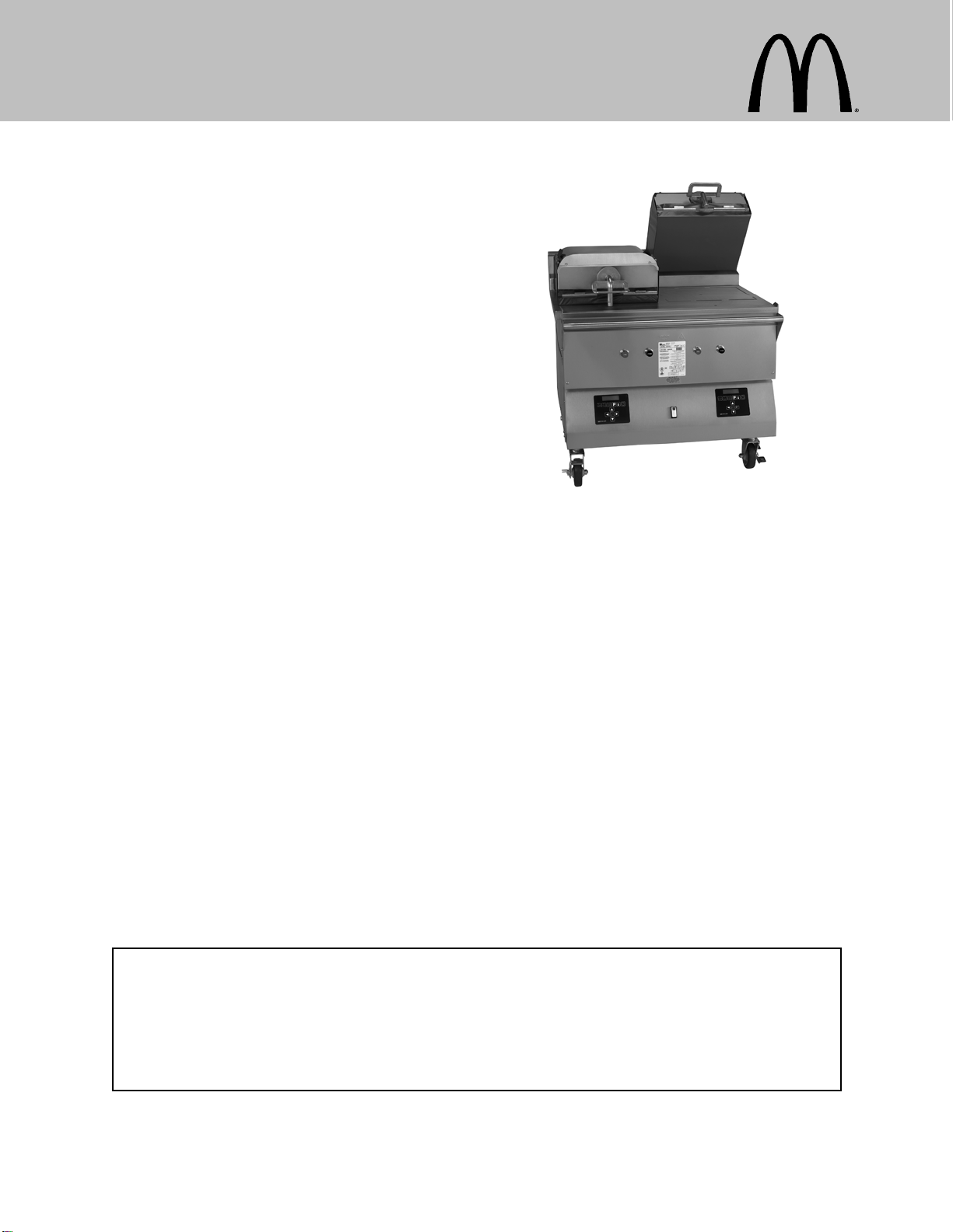
Clamshell Grill
Model C835
Place this chapter in the Grill section
of the Equipment Manual.
Manufactured exclusively for
McDonald's® by
Taylor Company
750 N. Blackhawk Blvd.
Rockton, IL 61072
Phone: (815) 624-8333
Toll Free Number
Outside Illinois:
1 (800) 228-8309
Inside Illinois:
1 (800) 851-5639
Fax: (815) 624-8000
Table of Contents
Introduction Page 1.....................................................
Safety Page 1..........................................................
Parts Identifications/Functions Page 4.....................................
Important to the Operator Page 10.........................................
Equipment Set Up Procedures Page 12.....................................
Menu Screens Page 16...................................................
Daily Cleaning Procedures Page 23........................................
Troubleshooting Guide Page 39............................................
Limited Warranty on Equipment Page 43....................................
Limited Warranty on Parts Page 45.........................................
Ordering/Service Information Page 48......................................
Non-Scheduled Maintenance Page 49......................................
System Set-up Page 49...................................................
Menu Items Page 54.....................................................
Auto Leveling Page 62....................................................
Warranty
Warranty information is contained in this Equipment Manual. Refer to the warranty information listed in the Limited
Warranty on Equipment and Limited Warranty on Parts sections and to the warranty classifications listed in the Parts
Identification/Function section when service is performed on your machine.
Itisrecommendedthattheoperatortakethenecessarytimetocarefullyreadthroughthecompletewarrantyinformation.
Thoroughly understand your warranty protection before you begin operation.
For any questions pertaining to the Taylor Warranty, please contact Taylor Company, Rockton, Illinois 61072.
This manual is for the exclusive use of licensees and employees of McDonald's Corporation.
E2010 McDonald's Corporation
All Rights Reserved January, 2010 (Original Publication)
(Updated May, 2016)
EM SD11
Printed in
The United States of America


1131202
INTRODUCTION
The Model C835 has two independent upper
platens. This grill provides automatic leveling
of the platens.
The grill is capable of cooking a variety of
products and features two cooking options,
AUTO and MANUAL.
AUTO Option: The grill automatically detects
the product placed on the grill plate (menu
items that are cooked using the clamshell,
only) and sets the appropriate cooking
parameters.
MANUAL Option: After the operator selects
the desired product to be cooked, the grill
automatically sets the appropriate cooking
parameters.
These grills provide all of the features of a flat
grill, as well as the advantages of two-sided
cooking.
All repairs must be performed by an
authorized Taylor service agent. The main
power supplies to the grill must be
disconnected prior to performing any repairs.
This grill is designed for indoor use only.
Note: Only instructions originating from the
factory or its authorized translation
representative(s) are considered to be the
original set of instructions.
SAFETY
Always follow these safety precautions when
operating the grill:
DO NOT operate the grill without
reading this operator's manual. Failure to
comply may result in equipment damage or
personal injury. This manual should be kept in
a safe place for future reference.
This appliance is to be used only by
trained personnel. It is not intended for use by
children or people with reduced physical,
sensory, or mental capabilities, or lack of
experience and knowledge, unless given
supervision or instruction concerning the use
of the appliance by a person responsible for
their safety. Children should be supervised to
ensure that they do not play with the
appliance.
DO NOT install the unit in an area
where a water jet could be used. DO NOT use
a water jet to clean or rinse the grill. Failure to
follow this instruction may result in serious
electrical shock. In addition, water may collect
inside the grill and destroy electrical
components and cause injury from hot steam.
DO NOT operate the grill unless it is
properly grounded. Failure to comply may
result in equipment damage or personal injury.
This unit is provided with an equipotential
grounding lug that is to be properly attached to
the rear of the frame by the authorized
installer. The installation location is marked by
the equipotential bonding symbol (5021 of IEC
60417-1) on both the removable panel and the
equipments frame.
SDO NOT operate the grill with larger
fuses than specified on the data label.
SAll repairs must be performed by an
authorized Taylor service agent. The
main power supplies to the grill must
be disconnected prior to performing
any repairs.
SCord Connected Units: Only Taylor
authorized service technicians may
install a plug on these units.

2131202
SStationary appliances which are not
equipped with a power cord and a plug
or other device to disconnect the
appliance from the power source must
have an all-pole disconnecting device
with a contact gap of at least 3 mm
installed in the external installation.
SAppliances that are permanently
connected to fixed wiring and for which
leakage currents may exceed 10 mA,
particularly when disconnected or not
used for long periods, or during initial
installation, shall have protective
devices such as a GFI, to protect
against the leakage of current, installed
by the authorized personnel to the
local codes.
SSupply cords used with this unit shall
be oil-resistant, sheathed flexible cable
not lighter than ordinary
polychloroprene or other equivalent
synthetic elastomer-sheathed cord
(Code designation 60245 IEC 57)
installed with the proper cord
anchorage to relieve conductors from
strain, including twisting, at the
terminals and protect the insulation of
the conductors from abrasion.
If the supply cord is damaged, it must
be replaced by an authorized Taylor
service technician in order to avoid a
hazard.
Failure to follow these instructions may result
in personal injury, equipment damage, or poor
grill performance.
WARNING: Improper installation, adjust-
ment, alteration, service or maintenance
can cause property damage, injury or
death. Read the installation, operating
and maintenance instructions thoroughly
before installing or servicing this equip-
ment.
SThis appliance must be isolated from
all combustible construction and
materials including, but not limited to;
walls, partitions, furniture, floors,
curtains, paper, boxes, and
decorations. Failure to comply may
result in fire and cause destruction and
severe injury.
FORYOURSAFETY
Do not store or use gasoline or other
flammable vapors or liquids in the vicinity
of this or any other appliance.
SDO NOT obstruct the ventilation
openings at the rear of this appliance.
SDO NOT obstruct the flow of air in and
around the grill.
SDO NOT operate the grill unless all
service panels and access doors are
attached with screws. Failure to comply
may result in personal injury from gas
or electrical components.
USE EXTREME CAUTION while
setting up, operating, and cleaning the grill.
Avoid coming in contact with the hot grill
surfaces or with the hot grease. Failure to
comply will result in burn injuries.

3
SThe grill must be placed on a level
surface.
STo ensure thorough cleaning, the grill
must be pulled away from the wall.
When returning the grill to its original
position, use extreme caution to
smoothly and slowly roll the grill
backward into place.
Failure to follow these instructions may cause
the grill to tip and can result in severe
equipment damage or personal injury.
NOTICE all warning labels that have
been attached to the grill to further point out
safety precautions to the operator.
HAZARD COMMUNICATION STANDARD
(HCS) - The procedure(s) in this manual
include the use of chemical products.
These chemical products will be
highlighted with bold faced letters followed
by the abbreviation (HCS) in the text
portion of the procedure. See the Hazard
Communication Standard (HCS) manual for
the appropriate Material Safety Data
Sheet(s) (MSDS).
This piece of equipment is made in America
and has American sizes on hardware. All
metric conversions are approximate and vary
in size.
NOISE LEVEL: Airborne noise emission does
not exceed 70 dB(A) when measured at a
distance of 1.0 meter from the surface of the
machine and at a height of 1.6 meters from
the floor.
These instructions are valid only if the country
code symbol appears on the appliance. If the
symbol does not appear on the appliance,
refer to the technical instructions which give
the necessary instructions for adapting the
appliance to the utilization conditions of that
country.
If the crossed out wheeled bin symbol
is affixed to this product, it signifies that this
product is compliant with the EU Directive as
well as other similar legislation in effect after
August 13, 2005. Therefore, it must be
collected separately after its use is completed,
and cannot be disposed as unsorted municipal
waste.
The user is responsible for returning the
product to the appropriate collection facility, as
specified by your local code.
For additional information regarding applicable
local laws, please contact the municipal facility
and/or local distributor.

4110203
PARTS IDENTIFICATION/FUNCTIONS
C835 Exploded View (See Figure 1)
ITEM PART NO. DESCRIPTION QTY. FUNCTION WARR.
CLASS
1X72962 Panel A.-Side Upper
Left 1Provides access to internal compon-
ents for service and cleaning. 103
2024298 Screw-10-32 x 3/8 6Secures the panel to the frame. 000
3072967 Panel-Side Left 1Provides access to internal compon-
ents for service and cleaning. 103
4X78330-SER Kit A.-Grease Shield 2Prevents grease migration. 103
4a 078329 Fastener-Snap 16 Fastens grease shields to rear
shroud of grill. 000
4b 078285 Shield-Grease 4Prevents grease migration. 000
5X73152 Panel A.-Back
Service (Upper) 1Provides access to internal compon-
ents for service and cleaning. 103
6X72958-SER
(Includes
6a-6e)
Panel A.-Back Panel
(Lower) 1Provides access to internal compon-
ents for service and cleaning. Has a
two speed fan connector built into
the panel.
103
6a 072959 Panel-Back Two
Speed
Fan
1Provides access to internal compon-
ents. Has a two speed fan connector
built into the panel.
103
6b 053889 Cap-Protective
Plastic 7/8 THD 1Protects the plug on the end of the
back panel harness. 000
6c X74158 Harness A.-Back Pnl 1Connects to the internal harness in
the grill for the 2 speed fan. 103
6d 078327 Nut-Locking Conduit
1/2” 1Secures the back panel harness
connector to the panel. 000
6e 044823 Connector-Mate Lock 1Connects the back panel harness to
the internal wire harness. 103
7X72965 Panel A.-Side Upper
Right 1Provides access to internal compon-
ents for service and cleaning. 103
8072968 Panel-Side Right
(Lower) 1Provides access to internal compon-
ents for service and cleaning. 103
9078377 Caster-5” 7-5/8 Stem 2Allows grill mobility. 103
10 073240 Caster-5” Swivel
w/Lock 2Prevents grill movement. 103
11 X72491-SER Control-Display 2Controls all functions of the grill. 103
12 076989-WP Switch-Rocker-DPST
10A (Fan Interlock) 1Activates power to the grill and the
exhaust fans. 103
13 076012 Button-Operator-
Black (Standby) 2Activates the cook cycle, keeps the
upper platen in the closed position,
and displays the message
“STANDBY” on the control. When
pressed twice within five seconds,
the upper platen will automatically
lower into the Standby position.
000
14 076011 Button-Operator-Red
(Raise) 2Cancels the Standby mode, raises
the upper platen, and deactivates the
Cook cycle.
000

5110203
C835 Exploded View
Figure 1

6101022
C835 Front View
ITEM PART NO. DESCRIPTION QTY. FUNCTION WARR.
CLASS
1076989-WP Switch-Rocker-DPST
10A (Fan Interlock) 1Activates power to the grill and the
exhaust fans. 103
2076011 Button-Operator-Red
(Raise) 2Cancels the Standby mode, raises
the upper platen, and deactivates
the Cook cycle.
000
3076012 Button-Operator-Black
(Standby) 2Activates the cook cycle, keeps
the upper platen in the closed
position, and displays the
message “STANDBY” on the
control. When pressed twice
within five seconds, the upper
platen will automatically lower into
the Standby position.
000
4X72491-SER Control-Display 2Controls all functions of the grill. 103
Figure 2

7
C835 Right Side View
ITEM PART NO. DESCRIPTION QTY. FUNCTION WARR.
CLASS
1072472 Handle-Platen 2The handle sits solidly on the
lower cook surface when the
platen is lowered.
103
Figure 3

8
C835 Left Side View
ITEM PART NO. DESCRIPTION QTY. FUNCTION WARR.
CLASS
1073129 Manifold A. 1Regulates air pressure for platen
operation. 103
Figure 4

9121108
C835 Accessories
ITEM PART NO. DESCRIPTION QTY. FUNCTION WARR.
CLASS
1076155 Rod-Release Material 2Holds the release sheet. 103
2072673 Clip-Release Material
w/Tab 8Secures the non-hemmed end of
the release material to the release
material bar.
000
3076390 Hose A.-Flexible Gas 1Supplies the gas to the unit. 103
4073317 Sheet-Release
Box of 6 1Non-stick barrier used to protect
the upper platen. 000
*5 081432 Sheet-Lower Release
(Box of 12) 1Non-stick barrier used to protect
the lower cook surface. 000
*For grill markets using lower release sheet, only.
Figure 5

10 101022
IMPORTANT TO THE OPERATOR
Important to the Operator Exploded View (See Figure 6)
ITEM DESCRIPTION FUNCTION
1Fan Interlock Switch This switch activates power to the grill and the exhaust fans.
2ON/OFF Key This key is used to turn the controller on and off to start a
preheating mode and to auto-gap the platen. The key must be
pressed and held for three seconds to activate, in order to
prevent unintended operation.
3AM/PM Key This key is used to toggle back and forth between the AM and PM
menu item lists.
4MANUAL/AUTO Key This key is used to toggle back and forth between the Manual
and Auto modes.
5Left Arrow Key This key is used to scroll through menu items when cooking in the
Manual mode. (Inactive in the Auto mode.)
6Down Arrow Key While in the Menu mode, this key is used to decrease a numerical
value and to scroll through the characters when entering a new
menu item or modifying an old one. (Inactive in the Auto mode.)
7OK Key This key is used to accept the information entered.
8Right Arrow Key This key is used to scroll through menu items when cooking in the
Manual mode. (Inactive in the Auto mode.)
9Up Arrow Key While in the Menu mode, this key is used to increase a numerical
value and to scroll through the characters when entering a new
menu item or modifying an old one. (Inactive in the Auto mode.)
10 Program Key This key is used to enter and exit the Programming mode.
11 Temperature Key When pressed and held for 3 seconds, this key will access the
Probe Calibration screen.
12 Cook Time Key This key is used to change the remove time of a specific menu
item. To change a specific cook time, the item must be selected in
the Manual mode. (Note: Press and hold the Cook Time key for
three seconds to activate.)
13 Liquid Crystal Display This screen displays menu options and information.

11 101022
Important to the Operator
Figure 6
Symbol Definitions
To better communicate in the International
arena, the words on many of our operator
keys have been replaced by symbols to
indicate their functions. Your Taylor equipment
is designed with these International symbols.
The following chart identifies the symbol
definitions.
= ON/OFF
=AM/PM
= PROGRAM
= TEMPERATURE
=TIME

12
EQUIPMENT SET-UP PROCEDURES
Installing Upper Platen Release Sheets
1. Slide the release material retention bar
through the loop in the release sheet.
(See Figure 7.)
Figure 7
2. Engage the material retention bar into the
hooks provided on the platen.
(See Figure 8.)
Figure 8
3. Center the release sheet on the bar. Pull
it tightly over the release material bar
located in the front of the platen. Secure
the sheet with two locking clips.
(See Figure 9.)
Figure 9
4. Carefully wrap the release sheet side
flaps over the cover rails and secure the
sheet with locking clips. (See Figure 10.)
Figure 10
IMPORTANT! Do not crease the release
sheet. This will greatly reduce the life
of the sheet.
5. Make sure the release sheets are tight
across the upper platen surface.
6. Repeat these steps for the other upper
platen.

13 121102
Installing Lower Release Sheets
(Grills Using Lower Release Sheets)
Note: The following steps pertain to grill
markets using lower release sheets, only. If
lower release sheets are not used, proceed to
“Start-Up of the Grill” on page 15.
WARNING! Upper release sheets
cannot be used on the lower grill surface. Poor
quality and potential food safety issues will
occur.
1. Clean the grill with a sanitizer-soaked grill
cloth to remove any debris on the grill.
(See Figure 11.)
Figure 11
2. Place the fan interlock switch in the ON
position. The controller will display the
message “OFF”. (See Figure 12.)
Figure 12
3. Press the key for 3 - 5 seconds. “AM
TOO COOL” and “AM FOLDED EGGS -
CLAM” will be displayed on the control
screen.
4. The screen will then display, “CLEAN
GRILL SURFACES,” followed by “CLOSE
PLATEN FOR AUTO LEVELING.”
5. Using a sundae spoon, distribute two level
spoonfuls of soy adhesion flakes over a
warm 3 ft. (1 m.) grill surface, allowing the
flakes to melt. (See Figure 13.)
Figure 13
6. Using a clean squeegee, spread the
flakes on the cooking zone.
(See Figure 14.)
Figure 14
7. Put on heat-resistant gloves.
(See Figure 15.)
Figure 15

14 121101
8. With the longest side of the lower release
sheet facing the back of the grill, hold the
release sheet about one inch from the
end of each side. Align the back edge of
the release sheet with the back splash
and the side edge of the grill.
(See Figure 16.)
Figure 16
9. Using the grill squeegee, gently squeegee
out air bubbles, making sure not to crease
or fold the release sheet. (See Figure 17.)
Figure 17
10. Repeat the last 2 steps for the other
half of the grill surface. The release
sheets will overlap about 1” (25 mm) in
the middle.
Note: When properly applied, the release
sheet will lay flat, with only a few small air
bubbles.
11. Press the Standby button to close the
platen. (See Figure 18.)
Figure 18
12. After the platen has closed, the grill will
start heating up to the proper
temperature. The control will display the
following message until the grill has
reached the proper temperature, ”TOO
COOL FOR AUTO LEVELING”.
13. When the grill has reached the proper
temperature, the screen will display,
“PLEASE WAIT FOR AUTO LEVELING”.
14. When the Auto Leveling is complete, the
upper platen will raise. The screen will
display the product that had been
selected.
The release sheet must be changed when:
SProduct sticks to the release sheet.
SCarbon builds up, causing problems in
taste or appearance.
SThere is a tear in the release sheet in
the cooking area.
SThe release material substance is worn
from the release sheet.
Note: Reverse the cooking side of the release
sheets on a daily basis.
Care of Release Sheets
SDO NOT fold or crease.
SDO NOT touch with any sharp object or
abrasive.
SDO NOT hose with hot water or soak in
water.
SDO NOT place under other objects.

15
Start-Up of the Grill
IMPORTANT: The lower grill plate and the
upper platen MUST BE CLEAN before starting
these procedures.
Note: Grills that use lower release sheets
require start up of grill before installation of
lower release sheets. (See page 13.)
1. Place the fan interlock switch in the ON
position. The controller will display the
message “OFF”. (See Figure 19.)
Figure 19
2. Heat up the grill by pressing the key
for 3 - 5 seconds. “AM TOO COOL” and
“AM FOLDED EGGS - CLAM” will be
displayed on the control screen.
(See Figure 20.)
Figure 20
3. The control will first display, “CLEAN
GRILL SURFACES” and then display,
“CLOSE PLATEN FOR AUTO
LEVELING.”
4. Press the Standby button to close the
platen. (See Figure 21.)
Figure 21
5. After the platen has closed, the grill will
start heating up to the proper
temperature. The control will display the
following message until the grill has
reached the proper temperature, ”TOO
COOL FOR AUTO LEVELING”.
6. When the grill has reached the proper
temperature, the screen will display,
“PLEASE WAIT FOR AUTO LEVELING”.
7. When the Auto Leveling is complete, the
upper platen will raise. The screen will
display the product that had been
selected.

16 140908
MENU SCREENS
Limited access to menu screens is available
through the Operator Menu or the Manager
Menu. In order to enter the Operator Menu or
the Manager Menu, individual passcodes must
be entered.
Operator Menu - Passcode Access
The Operator Menu gives limited MENU and
SYSTEM SETUP access. Access to this menu
is intended for day to day operations
(whomever is responsible for Beef Integrity).
To enter the Operator Menu, press the
key to display “PROGRAMMING.” Press the
key to display the passcode entry
screen. Enter the Operator Menu passcode by
pressing the keys in this order:
All menu items will be visible, except “ADD
ITEM”. The following parameters are available
for each menu item:
SAM/PM
SREMOVE IN
SREMOVE ALARM
SMUST REMOVE IN
SPREP BREAD IN
SPREP ALARM
The following SYSTEM SETUP parameters
will be available:
SPROBE CALIBRATION
STEMPERATURE DISPLAY
SAUTO CLOSE
SSPEAKER VOLUME
STOO COOL DELAY
Manager Menu - Passcode Access
The Manager Menu gives access to all MENU
items and limited SYSTEM SETUP access. To
access the Manager Menu, press the
key to display “PROGRAMMING.” Press the
key to display the passcode entry
screen. Enter the Manager Menu passcode by
pressing the keys in this order:
All MENU items will be visible, including “ADD
ITEM”. All parameters are available for each
menu item.
SREMOVE IN GAP
SSTAGE 1 TIME
SSTATE 1 GAP
STOP TEMPERATURE
SBOTTOM TEMPERATURE
SAUTO SELECTION
SAUTO GAP
The following SYSTEM SETUP parameters
will be available, in addition to those available
in the Operator Menu.
SAUTO PROD MELT TIME
SGATEWAY ENABLE
SDATE
STIME
S24 HOUR STORE
SAUTO IDLE TOP TEMP
SAUTO IDLE BOTTOM TEMP
SSTANDBY ALERT

17
Product Selection
The key allows the operator to cook in
either the AUTO mode or in the MANUAL
mode.
AUTO Mode
In the AUTO mode, the grill automatically
detects the product that is placed on the lower
grill plate and sets the appropriate cooking
parameters. The AUTO option is only
available for clam items.
Note: In “MENU ITEMS”, the AUTO
SELECTION parameter must be set to
“YES”.
MANUAL Mode
In the MANUAL mode, the operator selects
the desired product to be cooked.
To select a product using the MANUAL item
option, perform the following steps.
1. Press the key. “AM” will be
displayed on the control screen. If “PM” is
desired, press the key one more
time.
2. Use the or keys to scroll
through the various product menu
selections. Continue this process until the
desired product is displayed. The product
that is displayed will be selected.
Patty Placement
Placement procedures of meat products must
be followed on the grill. Meat must be placed
on the lower grill plate, two patties at a time,
from front to back, per the patty placement
guide on the next page. When the cook cycle
is complete, the upper platen will raise.
The patties must be removed immediately
after the upper platen has been raised to the
OPEN position and the meat has been
seasoned. Remove the patties, one at a time,
from front to back and right to left, per the
patty placement guide on the next page.
The maximum amount of meat patties to be
cooked on each side of the grill is as follows.
S8 regular (10:1) patties
S6 quarter pound (4:1) patties
S4 Angus patties
S8 sausage patties
S6 circular bacon
Thefollowingchartistobeusedasthepatty
placement guide.

18 121221
Model C835
IntelliGaptGrill
10:1, 4:1, Sausage, Circular Bacon,
and Patty Placement Guide
Note: Patty placement procedures for International Markets may differ. Follow the recommendations
of your local McDonald's authorities.
Table of contents
Other McDonald's Commercial Food Equipment manuals