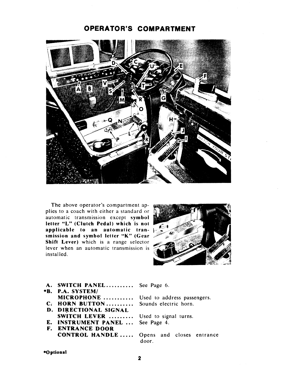
MCi MC8 Crusader 1977 User manual

56008
operator's
manual
COACH INFORMATION NETWORK
www.coachinfo.com

NOTICE:
THIS
IS
A PHOTOCOPY
REPRODUCTION OF A
PUBLICATION THAT
IS
OUT OF PRINT.
THEREFORE SOME
DEGRADATION OF COPY
IS
TO BE EXPECTED.

TO THE DRIVER
This
manual
has been
prepared
to give you the necessary
information
to successfully
operate
the
CRUSADER
MODEL
MC-8
Intercity
Coach
with a
standard
or
automatic
transmission
installation.
To
obtain
the most satisfactory coach
performance
and
assure
your
passengers
maximum
safety
and
comfort,
complete
knowledge
of
your
coach
and
its
correct
operating
practice
is
important.
This
manual
contains
information
useful in
normal
operation
or
when
emergencies
or
abnormal
conditions
oc-
cur.
Any
malfunction
which
interferes
with satisfactory
operation
of
the coach
should
be
reported
to
responsible
service
personnel
for
immediate
attention,
particularly
if
safety may be affected.
DRIVING CONTROLS
All
hand
and
foot
controls
used in the
normal
operation-
of
the
coach,
and
all gauges,
tell-tale
lights
and
switches
are
located
in the
driver's
compartment.
They
are
so
arranged
as to be
conveniently
reached
by you while in the
driver's
seat.
These,
as well
as
other
controls
and
equipment
which you
may need to use
under
abnormal
or
emergency
conditions,
are
described
and
illustrated
throughout
this manual.
Information
is
included
concerning
minor
service
and
maintenance
procedures
with which you
should
be familiar.
The
Mork
of
Re1-ponsibility
MOTOR
COACH
INDUSTRIES, INC.
PEMBINA D NORTH DAKOTA D U.S.A.
IN
CANADA-
MOTOR
COACH
INDUSTRIES LIMITED
1149 ST. MATTHEWS AVENUE
D
WINNIPEG
D
MANITOBA
R3G
OJ8
JULY, 1977
PRINTED
IN
CANADA
1

OPERATOR'S COMPARTMENT
The
above
operator's
compartment
ap-
plies to a
coach
with
either
a
standard
or
automatic
transmission
except
symbol
lelter
"L"
(Clutch
Pedal)
which is not
applicable
to an
automatic
tran,.
smission
and
symbol
lelter
..
K"
(Gear
Shift Lever)
which
is
a
range
selector
lever
when
an
automatic
transmission
is
installed.
A.
SWITCH
PANEL
.........
.
•B.
P.A.
SYSTEM/
MICROPHONE
..........
.
c~
HORN
BUTTON
.........
.
D.
DI~ECTIONAL
SIGNAL
SWITCH
LEVER
........
.
E.
INSTRUMENT
PANEL
..
.
F.
ENTRANCE
DOOR
CONTROL
HANDLE
.....
•Optional
See Page 6.
Used
to
address
passengers.
Sounds
electric
horn.
Used
to signal
turns.
See Page 4.
Opens
and
closes
entrance
door.
2

G.
WINDSHIELD
WIPER
l:ONTROLS
..............
.
H.
ENTRANCE
DOOR
LOCK
OVERRULE
SWITCH
....
I.
ACCELERATOR
PEDAL
.
J.
BRAKE
PEDAL
.........
.
K.
GEAR
SHIFT
LEVER
...
.
RANGE SELECTOR LEVER
...
FOR
AUTOMATIC
TRAN-
SMISSIONS ONLY. SEE PHOTO
Controls
windshield
wiper
motors.
Releases
door
air
lock
if
it fails
to
do
so
when
door
control
handle
is
opera.ed.
Controls
engine
speed.
Applies
service
brakes.
Selects
transmission
gear
for
standard
transmission
only.
L.
CLUTCH
PEDAL.........
Engages
and
disengages
engine
clutch
with
standard
transmissions
only.
*M.
P.A.
SYSTEM
VOLUME
CONTROL................
Adjusts
P.A. System.
N.
HEADLIGHT
DIMMER
SWITCH
. . . . . . . . . . . . . . . . . .
Selects
headlights
high
or
low
beam.
*
FOGLIGHT
SWITCH
(NOT
SHOWN)
NEXT
TO
HEADLIGHT
DIMMER
SWITCH
......
.
0.
SLOTTED
FASTENER
KEY
.....................
.
*P.
AIR
HORN
VALVE
......
Q.
DRIVER'S
HEATER
WATER
VALVE
........
..
R.
TURN
LIGHT
FLASHER.
S.
DASH
LIGHT
CONTROL
T.
WINDSHIELD
WASHER
Controls
foglights.
Opens
all
compartments
closed
with
slotted
fasteners.
Sounds
air
horn.
Controls
water
flow to
driver's
heater
and
defroster.
Operates
turn
signal
lights.
Controls
instrument
panel
gauge
lights.
CONTROL................
Operates
windshield
washers.
*Optional
3

U.
DRIVER'S
HEATER
AIR
CONTROL................
Selects fresh
or
recirculated
air
into
driver's
heater/
defroster
system.
V.
ILLUMINATION
CONTROL................
Controls
instrument
&
switch
panel
legend lights.
_,
_____
...
_
DRIVER'S
FRESH
W.
DRIVER'S
FRESH
AIR
GASPER
.................
.
When
opened,
allows
fresh
air
into
driver's
compartment.
X.
DRIVER'S
HEATER
OR
AIR
COND.
GASPER
.....
When
opened,
al lows
selected
heated
or
cooled
air
into
lower
driver's
compartment
area.
Al
INSTRUMENT PANEL
A
S U V
OD
X
A.
OIL
PRESSURE
GAUGE
.
8.
SPEEDOMETER
.........
.
4
Indicates
oil
pressure.
Indicates
vehicle
speed.

C. WATER TEMP.
GAUGE
..
D.
AIR
PRESSURE
GAUGE.
E.
HEADLIGHT
HI-BEAM
Indicates
engine
temperature.
Indicates
coach
air
system
pressure.
TELL-TALE
..
. . . . . . . . . . . .
Glows
when
headlight
hi-beams
are
on.
F. "HOT ENG" TELL-
TALE
. . . . . . . . . . . . . . . . . . . . . Flashes
and
buzzes when engine
overheated.
G. "LOW OIL" TELL-
TALE
. . . . . . . . . . . . . . . . . . . . . Flashes
and
buzzes when oil
pressure
too low.
*H. "LOW WATER" TELL-
Flashes
and
buzzer
operates
TALE
. . . . . . . . . . . . . . . . . . . . . when
water
level
too
low.
I.
"LOW
AIR"
TELL-
TALE
. . . . . . . . . . . . . . . . . . . . . Flashes
and
buzzes when
coach
air
pressure
too
low.
J.
TRAILING
AXLE
BELLOWS LOW
AIR
TELL-TALE . . . . . . . . . . . . . .
Glows
when
air
pressure
low
in
trailing
axle
bellows.
K. "EMERG. BRAKE"
TELL-TALE . . . . . . . . . . . . . . Flashes when
emergency
brakes
are
applied.
L.
"A/C HI-LO" TELL-
TALE
....................
.
M.
"TURN
LIGHT" TELL-
TALE
....................
.
N.
"HAZARD
WARNING"
Glows
or
flashes
when
air condition-
ing
system
malfunctions
Flashes when
turn
signals
are
on.
TELL-TALE . . . . . . . . . . . . . . Flashes when
hazard
warning
is
operated.
*O. "LOW FUEL" TELL-
TALE
. . .
..
. . . . . . . . . . . . . . . .
Glows
when fuel supply
is
low.
P.
"B.U. LITE" TELL-
TALE
...
-.
. . . . . . . . . . . . . . . . .
Flashes
when
back-up
lights
are
on.
Q.
"NOT
GEN." TELL-
TALE
. . . . . . . . . . . . . . . . . . . . .
Glows
when
generator
not
charging.
*R.
"LAV.
EM
ERG."
TELL-TALE
.............
.
S.
"HEAT
ON" TELL-
Glows
and
buzzes
if
emer-
gency
button
in
lavatory
is pressed.
TALE
. . . . . . . . . . . . . . . . . . . . . .Glows when heating system
operating.
T. "STOP LIGHT"
TELL-TALE
...•..........
*U.
"RETARDER"
TELL-
TALE
....................
.
•Optional
Glows
when
both
rear
stoplights
are
on.
Glows
when switched on.
5

•V.
"FIRE
ALARM"
TELL-TALE
........•.....
X.
"EMERG.
STOP" SWITCH
Y.
WINDSHIELD
WASHER
Glows
and
operates
buzzer.
Stops engine if master
control
switch in
"OFF"
position
fails to
do
so.
CONTROL................
Operates
windshield
washers.
Z.
WINDSHIELD
WIPER
CONTROLS...............
Controls
windshield
wiper
motors.
AA.
"MASTER CONTROL"
SWITCH
.................
.
BB.
STARTER
BUTTON
&
ENGINE
OVERRULE
....
•cc. FUEL
GAUGE
...........
.
(NOT
SHOWN)
•DD.
"FOGLIGHT"
TELL-TALE
.............
.
Allows
operation
of
engine
and
accessories when in
"ON"
position. Stops engine in
"OFF"
position.
Engages
starter
and
in
emergency
press
button
and
hold
to
overrule
automatic
engine
shutdown
controls
if
necessary to
move
to
safety
if
automatic
controls
stop
engine.
Indicates
amount
of
fuel in
tank.
Glows
when switched on.
SWITCH PANEL
A. SOLENOID SHIFT
REVERSE
8.
FAST
IDLE
..............
.
•Optional
Engages
reverse
solenoid
for
shift into reverse
gear
with
standard
transmission
only.
Engages engine fast idle.
6

C.
DRIVER'S
AIR
CONDITIONING
D.
DRIVER'S
HEATER/
DEFROSTER
FAN
Controls
driver's
air
conditioning
system.
SWITCH
..................
Controls
driver's
heater
and
defroster
fans.
E
PASSENGER
AIR
COND/HEATING
....
F.
COACH
HEAT
Controls
air
conditioning
and
heating
system.
CONTROL................
Controls
interior
temperature.
G.
STEPLIGHT
AND
CHIME
. . . . . . . . . . . . . . . . . . .
Illuminates
step
light
and
allows
use
of
passenger
H.
INDIRECT
LIGHTS
.....
.
I.
DRIVER'S
LIGHT
.......
.
J.
ILLUMINATION
CONTROL
...............
.
K.
DASH
LIGHT
CONTROL
*L.
LAV
A
TORY
DOOR
KEY
M.
"HAZARD"
SWITCH
.....
N.
HEADLAMPS
...........
.
0.
CLEARANCE
AND
IDENTIFICA
Tl()N
LAMPS
P.
VENT
CONTROL
KNOB
...................
.
*Q.
EMERGENCY
BRAKE
RELEASE
SWITCH
(NOT
SHOWN)
R.
AIR
DEFLECTOR
.......
.
*S.
TRAILING
AXLE
UNLOADING
SWITCH
...
(NOT
SHOWN)
•Optional
chime.
Controls
interior
indirect
lights.
Controls
light
above
driver's
compartment.
Controls
instrument
and
switch
panel
legend
lights.
Controls
instrument
panel
gauge
lights.
Locks
or
unlocks
lavatory
door.
Operates
all
front
and
rear
turn
signal lamps.
Controls
headlights.
Controls
exterior
clearance,
identifi-
cation,
license, tail
and
destination
sign lights. Also
interior
aisle
and
run-
ning lights. Allows
passenger
to
turn
on
prefocused
reading light.
Opens
or
closes
air
vent.
NOTE:
Coaches
prior
to
Unit
No.
31843 only
In an
emergency
to
release
parking
brakes
push
&
hold
to
overrule
the
parking
brakes.
Directs
air
flow to
driver
or
driver's
window.
When
engaged
unloads
air
pressure
from
trailing
axle
bellows
from
35
P.S.I.
to 15
P.S.I.
7

ALARM SYSTEM
The
coach
is
equipped
with an
alarm
system
of
"TELL-TALE"
lamps
and
in
some cases a
buzzer
signal which
immediately
warns
the
driver
of
any
abnormal
operating
conditions.
The
"TELL-TALE"
lamps
are
located
on
the
instrument
panel ,in
front
of
the
driver.
TELL-TALE
LIGHT
"LOW
AIR"
BUZZER
CONDITION
"HOT.
ENG."
*"LAV.
EMERG."
"EMERG.
BRAKE"
"LOW
OIL"
PRESSURE
"NOT
GEN."
"HI-BEAM"
*"FOG
..
"STOP
..
"B.U."
*"FIRE
ALARM"
*"LOW
WATER"
*"LOW
OIL
LEVEL"
-
*"LOW
FUEL
LEVEL"
"TRAILING
AXLE
BELLOWS"
"A/C
HI-LO"
Yes
Air
pressure
low
Yes Engine
overheated
Yes
Emergency
in
lavatory
Emergency
brake
on
Yes Engine oil
pressure
low
Generator
not
charging
Headlight
high beam
on
Fog
Lights
on
Both
rear
stop
lights
on
Back
up
light
on
Yes
Overheating
(Engine
Compt.)
Yes Low
water
level
Yes Oil level low
I
~7<-
fuel remaining
Low
air
pressure
If
light stays
on
continuously,
system
is
malfunctioning
DRIVER'S SEAT
Driver's
seat may be
adjusted
fore
and
aft by pushing in. lock
lever located at left front
of
seat.
When
seat is
positioned,
release
lever.
The
seat
back
may be tilted
by
pulling
the
back
tilt
knob
at the
left
rear
side
of
seat.
To
return
seat
back
to a
forward
position,
grasp
seat
back
and
pull
forward
while
pulling
tilt knob.
The
back
of
seat
cushion
can
be tilted
up
or·down
by
grasping
the
cushion
tilt lever
at
left
center
of
driver's
seat
and
tur-
ning
forward
to lower
and
back-
ward
to raise. Seat may be
raised
by
grasping
and
firmly
pulling
seat
frame
up.
To
lower, raise seat to
highest
position
then, lower seat to
lowest position.
from
there
raise
seat to
desired
height.
SEAT
BELT
BACK
\
-TILT
I\
CUSHION
TILT
FORE
AND
AFT
The
seat
is
supplied
complete
with a
retractable
seat
belt
as
required
by
•Optional
8

State
and
Federal
Regulations.
The
seat
belt
may
be
fastened
by
slowly
pulling
the
buckle
over
and
across
the
lap
to
engage
the
buckle
on
the
tongue.
Sudden
pulling
of
the
belt
will
lock
the
reel.
No
special
adjustment
is
required
as
the
reel
device
is
self
adjusting.
If
seat
belt
assembly
operation
becomes
defective,
report
to
maintenance
personnel.
DRIVER'S
WINDOW
The
driver's
window
has a
small
sliding
section
at
the
lower
rear
of
window.
The
front
section
slides
rearward
to
open.
The
optional
drivers
window
is
similar
except
the
unit
is
double
glazed.
EMERGENCY ESCAPE
~
-~
#__.,
All
side
passenger
windows
can
be
opened
from
the
inside
for
emergency
escape
purposes.
Window
sash is
hinged
at
the
top
and
can
be
opened
by
pulling
out
and
up
on
the
release
bar,
then
pushing
window
sash
out.
Instruction
plates
are
mounted
below
the
sash
on
release
bars
at
each
seat
location.
EMERGENCY EXIT
HATCH
An
emergency
escape
hatch
is
located
in
the
roof
at
the
rear
of
coach.
The
opening
size is
18"
x
25".
To
open,
pull
handle
to
unlock
and
push
hatch
open.
To
close,
pull
handle
to
open
position
and
pull
until
hatch
is in
the
closed
position.
Push
handle
to
lock
hatch.
ENTRANCE
DOOR
CONTROL
u
The
entrance
door
is
provided
with
an
air-operated
lock.
The
door
is
opened
or
closed
by
means
of
a
door
control
handle
on
the
dash
to
the
driver's
right.
To
open,
turn
handle
clockwise;
counterclockwise
to
close.
The
air
lock
engages
automatically
when
the
door
is
closed,
disengages
to
open.
9

In
the
event
that
the
air
lock
mechanism
does
not
release
when
an
at-
tempt
is
made
to
operate
the
entrance
door
handle,
depress
the
overrule
switch
located
under
the
dash
near
the
center
of
the coach.
This
will
release
the
air
lock
regardless
of
the
position
of
the
door
control
handle.
IMPORTANT
If
air
lock
fails
to
engage
wh~n
entrance
door
is
closed,
immediately
advise
service
personnel
at next
service
stop.
Do
not
attempt
to
engage
while
coach
is
in
motion.
The
entrance
door
can be
opened
from
outside
the
coach
by means
of
a
release
knob
located
below
front
windshield.
After
pushing
release
knob,
pull
door
handle
and
open.
---,----,a,--,..-----:~~~-:--
.....
.--
...............
WINDSHIELD WIPERS & WASHERS
Two
air-operated
windshield
wipers
are
provided,
controlled
by two
small
knobs
situated
at the lower right
side)
of
the
instrument
panel.
Each
knob·
c~ntrols
its
corresponding
windshield
1
,
',,
,
wiper. ,
To
operate
wipers,
turn
control
,.
knob
for
wiper
desired
toward
direc-
tion
indicating
"ON"
until
required
speed
is
reached.
To
stop wipers,
turn
w
SHIELD
w
SHIELD
WASHER
WIPER
knob
to
"OFF"
position.
coNTROL
coNTRoLs
Air
operated
windshield
washers have an
independent
washer
control
knob
situated
on
the lower right
side
of
the
instrument
panel
alongside
the
two
windshield
wiper knobs.
To
operate
windshield
washers, press
control
knob.
The
washers
will
operate
for a
period
of
time while
the
control
knob
is
held
in this position.
Release
knob for
approximately
1/2
minute
to
allow
pump
to refill
before
operating
windshield
washer
again.
Turn
windshield
wipers
on
when
using
windshield
washers.
The
windshield
washer
reservoir
is
located
in the left
front
compartment
below
driver's
floor.
TACHOGRAPH (OPTIONAL)
Some
coaches
are
equipped
with
either
a
self
electrical
wound
"ARGO"
or
a manual
wound
"SANGAMO"
tachograph.
The
tachograph
is
an
option
in
addition
to the usual
speedometer
located
in
the
front
in-
strument
panel.
It
is
located
in
the
right
rear
baggage
compartment.
Some
coaches
are
equipped
with
an
optional
..
ARGO"
electronic
tachograph
which
is
located
on
the
dash
to
the
left
of
driver.
The
tachograph
head
illumination
is
controlled
by
the
instrument
and
dash
light
illumination
switch.
10

The
Tachograph
is a
recording
speedometer
indicating
driving
speed,
mileage
covered
and
the
time
of
day.
The
speeds
driven,
the
driving
and
stopping
periods
and
the
mileage
covered
are
simultaneously
recorded
on
a wax
coated
diagram
chart
that
is
rotated
by
the
instrument's
clock
movement.
Refer
to
Figure
1
(Argo
Unit)
FIGURE 1
SETTING CLOCK &
CHANGING CHART
NOTE:
It is
most
important
that
the
tachograph
never
be
opened
or
closed
while
the
coach
is in
motion
to
avoid
damaging
the
chart
and
the in-
strument.
1.
Open
the
instrument
by
turning
the
key
or
knob
type
lock
at
the
top,
coun-
terclockwise.
3
ARGO
TACHOGRAPH
WITH
CHART.
NOTE: CHART MUST
HAVE
CENTER HOLE
AS
SHOWN.
DO
NOT
SUBSTITUTE
WITH
OTHER
TYPE
CHARTS.
2. Set
the
time
by
turning
setting
wheel
No.
1.
Fill
in
name,
date,
mileage
and
starting
time
on
chart.
3.
To
install
chart
lift
clamping
lever
No. 3,
place
chart
over
center
hub
and
flip
down
clamping
lever.
Reverse
procedure
to
remove
chart.
NOTE:
When
installing
chart,
the
hours
on
chart
from
1-12
are
AM
hours.
The
hours
from
13-24
are
PM
hours.
The
clock
should
be
set
and
the
chart
hours
will
match
the
time
of
day
at
arrow
No. 2.
Example:
3
P.M.
(time
of
day)
should
match
on
chart
(15)
at
arrow
No. 2.
4.
Insert
only
charts
that
are
applicable
to
the
Unit
0-80
MPH
and
refer
to
center
hole
No. 4
for
proper
type
(refer
to
Figure
1).
CAUTION:
Always
keep
a
chart
in
the
tachograph.
Refer
to
Figure
2
(Sangamo
Unit)
WINDING, SETTING
CLOCK &
CHANGING CHART
NOTE:
It is
most
impor-
tant
that
the
tachograph
never
be
opened
or
closed
while
the
coach
is in
motion
to
avoid
damaging
the
chart
grid
and
the
instrument.
1.
Open
the
instrument
by
turning
the
key
or
knob
coun-
terclockwise.
2.
Wind
the
clock
by
pulling
and
pushing
the
plastic
covered
lever
No. 1
located
to
the
left
rear
of
the
clock
door
assembly.
FIGURE 2
SANGAMO TACHOGRAPH WITH
CHART. NOTE: CHART MUST HAVE
CENTER HOLE AS SHOWN. DO
NOT
.SUBSTITUTE WITH OTHER
TYPE CHARTS.
11

Note:
Be
careful
not
to overwind the main spring.
3.
To
set the
correct
time
rotate
the metal gear No. 2, located at the right
rear
of
the clock
door
assembly. Fill in the name,
date,
mileage & starting
time on
chart.
4.
To
install, place
chart
(face side up)
on
the
chart
drive. Close
tachograph
door
and
turn
key
or
knob
clockwise.
5. When an individual
driver
record
is
required
the stylus No. 3 selection
lever for positions
1,
2
or
3 is used to indicate a change in drivers.
The
stylus will
record
events in any
of
the
three
positions.
6.
Insert
only
charts
that
are
applicable
to the Unit
0-90
MPH
and
refer to
center
hole
No. 4 for the
proper
type (refer to Figure 2)
CAUTION:
If
the
ualt
Is
to
be
idle
and
no
charts
used,
a
protecth·e
paper
or
chart
should
always
be
placed
between
the
styli
and
recor-
dlna
plate.
This
will
protect tlle
styli
when the
door
is
closed.
DESTINATION SIGN OPERATION
Open
sight hole
and
move
destination
sign to
desired
designation.
Rotate
handle
counterclockwise to take up slack in mechanism. This will
lock
upper
roller
to
prevent
sign
from
moving while coach is in motion.
ENGINE OPERATION
Controls
necessary to
start
and
stop
engine from the
operator's
com-
partment
are
mounted
on
the instrument panel in front
of
driver.
These
controls
are:
"MASTER"
switch: must be in the
"ON"
position when starting engine.
When switch is pushed
"OFF"
the engine will stop.
"STARTER"
switch: is
of
the
"momentary-on"
type,
and
must be held
in the depressed position to engage the starter. When released, switch will
return
to
normal
position.
"EMERGENCY
STOP"
switch:
is
of
the
"momentary-on"
type used to
stop engine if it fails to
do
so when the
"MASTER"
switch
is
moved to the
"OFF"
position.
The
switch must be pushed up to
operate
the emergency
stop" mechanism.
"ENGINE
OVERRULE"
is
obtained
by holding the
"STARTER"
switch in the depressed position (on coaches equipped with
optional
automatic
engine shutdown system). Switch should be held only long
enough to move coach to safety.
"GAUGES
AND
TELL-TALE
LAMPS"
Oil pressure and
temperature
gauges, together with
"LOW
OIL"
and
"HOT
ENG."
tell-tale lamps,
are
located in instrument panel in front
of
operator.
A buzzer sounds when
"HOT
ENG."
or
"LOW
OIL"
tell-tale
flashes.
STARTING THE ENGINE
1.
Make sure that the parking
brake
control
button
is
pulled up, applying
air-operated
parking brakes.
2. Make sure the remote
control
switch in
rear
panel
is
set for front
operation. Transmission shift lever
should
be
in
neutral position.
3. Place
"MASTER"
switch in the
"ON"
position.
4. Press
"START"
button to engage starter. Release
button
when the
engine starts. 12

NOTE:
When
the
..
MASTER"
swit<.:h
is in
the
"ON"
p(Jsition
the
..
LOW
OIL"
tell-tale
lamp
will flash
and
buzzer
will
sound.
The
"LOW
AIR"
tell-tale
lamp
will flash
and
buzzer
will
sound
if
air
pressure
is
below
60-65 lbs.
and
the
low
air
tell-tale
lamp
will
flash
and
buzzer
will
sound
until
the
air
pressure
of
100 lbs. is
r-ea<.:hed.
If
the
air
system
pressure
is
reduced
below
100
lbs.,
the
buzzer
and
tell-tale
will
not
come
on
until
the
air
pressure
is redu<.:ed
below
60-65 lbs.
Lamps
will
remain
illuminated
and
buzzer
will
sound
after
the
engine
has
started
until oil
pressure
is
over
3
lbs.
and
air
pressure
is
increased
above
65 lbs.
and
up
to
100 lbs.
Generator
1
amp
and
buzzer
will
remain
on
until
air
pressure
is
over
65
lbs.
and
up
to
100 lbs.
The
"Gen"
tell-tale
and
buzzer
will not
come
on
until
air
pressure
is
reduced
below
60-65
lbs.
CAUTION:
Do
not
engage
starter
continuously
for
longer
than
15
seconds
at a
time
for
starting
purposes
of
engine
only.
Allow
starter
motor
to
cool
before
a
second
attempt.
Continuous
·use
of
the
starter
without
allowing
a
cooling
period
may
damage
the starter
motor.
5.
Refer
to
"EMERGENCY
CONDITIONS"
for
instructions
regarding
starting
engine at
rear
of
coach.
COLD
WEATHER STARTING
The
coach
is
equipped
with a
cold
weather
starting
fluid
cup,
located
on
top
of
the engine
blower
housing.
If
temperature
is
below 35
degrees
F., it may be necessary to
use
starting
fluid capsules. Use
one
7 c.c.
capsule
at
temperatures
above
zero,
or
two at lower tem-
peratures.
DO
NOT
USE
MORE
THAN
TWO
FLUID
CAPSULES.
To
use
capsule,
lift
cover
of
starting
fluid cup,
insert
capsule,
force
down
over
pointed
tube
in
cup
and
squeeze until all fluid
enters
cup.
Remove
capsule
and
start
engine.
FIRE
WARNING
STARTING
FLUID CUP
Starting
fluid used in the
capsules
is
highly
inflammable,
poisonous
and is an
anaesthetic:
Do
not
smoke
while
using
or
handling
capsules,
and keep away from flame or
high
temperatures.
Avoid
inhaling
fumes
produced
by
starting
fluid.
ENGINE IMMERSION HEATER
(OPTIONAL)
Some
coaches
are
also
equipped
with an
electric
engine
immersion
heater
to assist in
cold
weather
operations.
A
receptacle
is
located
to
the
right
of
the
rear
engine service
door
for a 110
volt
AC
power
source.
The
engine
heater
s
..
ould
be used
whenever
the coach is
parked
for
an
ex-
tended
period
in
cold
weather
and
a
suitable
power
source
is
available.
13

CAUTION
Only
110
volt
AC
power
should
be
used,
and
the
power
cable
must
be
grounded
(three-prong)
type.
Make
sure
power
cable
is
disconnected
before
moving
coach.
WARM-UP
After starting the engine,
operate
it at a fast idle speed by engaging
"FAST
IDLE"
switch
on
driver's
panel.
Air-operated
parking brakes must
be
on
before the
"FAST
IDLE"
control
will operate~ and should be
kept
applied
during
warm-up. Observe gauges and tell-tale lamps frequently
during
warm-up
and
subsequent operation.
If
abnormal
conditions
develop
stop engine immediately and
determine
cause.
STOPPING ENGINE
1.
Apply parking
brake
and
place transmission shift lever in neutral.
2.
Idle
engine for
about
30 seconds, then move the
"MASTER"
switch to
the
"OFF"
position.
ENGINE EMERGENCY
STOP
The
"EMERG.
STOP"
switch
on
the instrument panel
is
provided
for stopping the engine O'NLY
when
placing
the
"MASTER"
switch to the
"OFF"
position fails
to stop the engine. When the
"EM
ERG.
STOP" switch
is
moved
to the
"ON"
po.sition, it energizes a
solenoid which releases a cam on
the engine
air
choke valve per-
mitting it to close, shutting
off
the
air
supply to the engine.
IMPORTANT
ENGINE AIR
CHOKE
VALVE
'CAM
When
the
"EM
ERG
ENCY
STOP"
switch
has
been
used
lo
slop
the
engine,
the
choke
valve
must
be
reset
manually
before
the
engine
can
be
operated.
Rotate
cam
until
shoulder
engages
cam
lock.
The
emergency
stop
is
to
be
used
ONLY
when
pushing
the
"MASTER"
switch
fails
to
stop
the
engine.
Do
not
re-start
until
the
reason
for
loss
of
control
has
been
corrected.
AIR PRESSURE
The
brakes, air suspension system and
other
systems and controls
of
the
coach depend on adequate
air
pressure for their operation. Air pressure in
the coach
air
system
is
therefore extremely important.
After
the
engine
has -been
started
...
LOW
AIR"
tell-tale light will flash
and
buzzer
will
sound
until air
pressure
is built up
to
60-65 lbs.
and
up
to
100
lbs.
To
assure
safe
braking. DO
NOT
MOVE
COACH
UNTIL
Al R
PRESSURE
IS
AT
LEAST
100
LBS.
14

If
during the normal operation the
"LOW
AIR"
tel-tale light flashes
and
buzzer
sounds
it
will indicate that air pressure has
reduced
below 60-65 lbs.
and
that air
pressure is
too
low,
stop
the vehicle
at
once
and
determine
reason
for
pressure
loss.
ENGINE OIL PRESSURE
Engine
oil
pressure
gauge is
mounted
on
instrument
panel
in
front
of
operator.
Normal
readings
with engine
hot
are:
IDLING:
3-4 lbs.
minimum:
GOVERNED
SPEED:
30
lbs.
minimum.
Engine
must
not
be
operated
when oil
pressure
falls
below
30 lbs. at
governed
speed
under
full
load.
lf
oil
pressure
drops
below a sate level, the
"LOW
OIL"
tell-tale
light will flash,
buzzer
will sound and
automatic
shut-off system (if so
equipped)
will stop the
coach
engine.
Refer
to
"ALARM
SYSTEM."
ENGINE TEMPERATURE
A gauge
marked
"WATER
TEMP."
is
located
on
the
instrument
panel
to
indicate
engine
temperature.
The
most efficient
operating
temperature
range
is
170-185 degrees F.
If
possible,
do
not move the
coach
after star-
ting a
cold
engine
until
temperature
reaches
at least 140
degrees
F.
If
the
engine
overheats
the
"HOT
ENG."
tell-tale
light
on
the
instrument
panel
will flash
and
warning
buzzer
will sound.
If
the
coach
is
equipped
with
automatic
shut-down
system, the
controls
will
stop
the
coach
engine.
GENERATOR
A tell-tale lamp
marked
"NOT
GEN."
is
located
on
the
instrument
panel
to
indicate
when
generator
is
not
charging.
With"
MASTER"
switch
on
and
engine not running
or
with engine running
and
generator
not
charging, this
light will be illuminated. Ifthe light goes on during normal
operation,
proceed
as
outlined
later
in this manual
under
"EMERGENCY
CONDITIONS."
Note:
The
generator
will not
charge
with
air
pressure
below
65
lbs.
The
generator
will not
charge
until the
air
is
built
up
to
JOO
lbs.
When
air
pressure
drops
below
JOO
lbs. but
not
under
65
lbs., the
generator
will
continue
charging.
ENGINE ALARM SYSTEM
The
engine is
equipped
with an
alarm
system to signal low oil pressure,
low
air
pressure
and
high engine
temperature.
"LOW
OIL"
"LOW
AIR"
and
"HOT
ENG."
tell-tales
are
located
on
the
instrument
panel. A
buzzer
sounds
if
any
of
these
conditions
occur.
Some coaches have an
automatic
shut-off
system
inter-connected
with
the engine
alarm
system to
shut
off
the engine in case
of
oil
pressure
drop
or
abnormal
temperature
rise.
This
feature
is
provided
to
prevent
damage
to the
coach
engine
if
either
of
these
abnormal
conditions
arise.
The
action
of
the
automatic
shut-down
controls
can be
overruled
in
or-
der
to move
the
coach
to a safe
location
by use
of
the
"ST
ARTER-
OVERRULE
SWITCH"
on
the
driver's
instrument
panel.
If
engine
is
shut
off
automatically,
turn
"MASTER"
switch to
"OFF"
position
momentarily
and
switch
on
again.
Depress
"STARTER-OVERRULE
SWITCH"
to
start
coach
and
hold
after engine
is
started
in
order
to move coach to a
safe location.
Under
no
circumstances
should
the engine be
operated
longer
than
ab-
solutely necessary after the engine has been
stopped
by
automatic
shut-
down
controls.
15

USE OF TRANSMISSION
(STANDARD)
CAUTION:
When
parking
vehicle,
gearshift
should
always
be left in
"NEUTRAL
POSITION".
The
transmission has four for-
ward
and
one reverse speeds. A
conventional shift lever located
to the right
of
the
operator's
seat
is used to select forward tran-
smission gears.
The
shift into
reverse gear is made by using the
shift
lever
and
an
electric
solenoid
controlled
by
the
"REVERSE"
switch on the
driver's
switch panel.
Always
start
coach
in
motion
at the
lowest
possible
engine
speed to prevent un-
necessary
clutch
wear.
REVERSE SHIFTING
SOLENOID
REVERSE
Close "Reverse" Switch For
Shift
Into Reverse Gear
The
"MASTER"
switch must
be
in the
"ON"
position before
"REVERSE"
switch will be operative.
To
shift into reverse gear stop coach completely. Depress clutch
pedal
and,
while holding the
"REVERSE"
switch in the
"ON"
position, move
shift lever into the second gear position from neutral.
To
shift out
of
reverse gear stop coach completely. With clutch
pedal
depressed, move gear shift lever into the neutral position.
It
is
not necessary to use the solenoid switch when shifting
out
of
reverse.
CAUTION
Solenoid
switch
should
be used
only
when gear
shift
lever is in
neutral
position,
otherwise
possible
locking
of
gears may result.
UP SHIFTING
Always
start
the coach in motion first gear, then change progressively
into
second,
third
and
fourth.
Do
not skip gears. Double-clutching is
recommended
when making each gear change. Remain in each tran-
smission speed until the engine reaches full governed speed before shifting
into the next highest gear.
DOWN SHIFTING
Double-clutching in downshifting is recommended. Always change to a
lower gear to avoid engine
"lug".
Lower gears should be used in
driving
up
or
down grades, when
operating
in ice, snow
or
mud.
Lower gears should be used when going down
grade
in
order
to make
use
of
the engine
as
a
brake
in
controlling
vehicle speed.
The
same tran-
smission gear should be used to go down a grade
as
would be used in clim-
16

bing it.
lfowever,
the engine
should
never
be
allowed
to
operate
at
a speed
higher
than
the
maximum
governed
speed.
Use
color
bands
on
speedometer
for
maximum
speeds
in each gear.
USE OF TRANSMISSION
AUTOMATIC
(OPTIONAL)
CAUTION:
When
parking
vehicle,
gearshift
should
always
be
left
in
"NEUTRAL
POSITION."
The
operation
and
driving
of
the
MC-8
coach
with an
automatic
tran-
smission
is
similar
to
that
of
a
normal
automobile
automatic
transmission.
In
order
to
attain
better
vehicle
per-
formance
proper
ranges
should
be
selected for speeds to
be
driven
depen-
ding
on
driving
conditions.
Each
for-
ward
range
starts
in 1st
gear
and
automatically
shifts
up
thru
the
gear
range selected.
RAKE
N-NEUTRAL
RANGE
is
used
when
starting
the
engine.
If
the
engine
starts
in any
other
position, the
neutral
start
switch
is
malfunctioning.
Use
this position
and
apply
the
parking
brake
when
vehicle
is
left
unattended
with
the
engine running.
CAUTION:
When
shifting
from
neutral
to a
drive
range, the
engine
should
be at
idle
speed.
D-FOURTH
RANGE
is
used for
normal
driving
conditions.
Upshifting
and
downshifting
is
automatic,
depending
on
speed
and
load.
3-THIRD
RANGE
is
used when traffic
conditions
do
not
permit
top
speed. Upshifting
and
downshifting
is
automatic.
2-SECOND
RANGE
is
used in
congested
traffic. Upshifting
and
down-
shifting is
automatic.
It
can also be used effectively
on
downgrades
to
take
advantage
of
engine
braking.
1-FIRST
RANGE
is used when
starting
the
vehicle
with an
extra
heavy
load,
pulling
through
mud
and
snow,
or
driving
up
steep grades.
It
may
also
be
used in
very
heavy
or
slow
moving
traffic.
R-REVERSE
RANGE
is used
for
backing
the
vehicle.
The
vehicle
should
be
completely
$topped
before
shifting from a
forward
range
to
reverse
or
vice versa.
Reverse
has
only
one
gear
position.
USING THE ENGINE TO SLOW THE VEHICLE
To
use
the
engine
as a
braking
force, shift to
the
next lower range.
However,
if
the
vehicle
is
exceeding
the
maximum
speed
of
that
lower
range,
use the service
brakes
to
reduce
speed
before
the
downshift
is
made.
CAUTION:·
PARKING
BRAKE:
There
is
no
"park."
position
in the tran-
17

smission
shift
pattern.
Therefore,
apply
the
parking
brake
to
hold
the
vehicle
when
it
is
unattended.
Be
sure
the
selector
lever
is
at
neutral
position.
CAUTION:
TOWING
COACH:
Before
towing
a
coach,
the
drive
line
must
be
disconnected.
This
applies
to
coaches
that
are
towed
on
the
road
to
a
repair
station.
Engines
cannot
be
started
by
towing
or
pushing.
Only
a
solid
type
link
can
be
used
between
towing
vehicle
and
coach.
A
safety
chain
should
also
be
attached
between
vehicles.
AUTOMATIC TRANSMISSION OIL LEVEL CHECK
Transmission
oil level
should
be
checked
at
regular
service
intervals
by
maintenance
personnel.
OIL SPECIFICATIONS
Only
Dexron®automatic
transmission
fluid is
recommended.
CAUTION:
INDICATIONS
OF
ABNORMAL
CONDITIONS:
Any
indication
of
possible
abnormal
conditions
should
immediately
be
brought
to
the
attention
of
maintenance
personnel.
The
transmission
should
not
be
operated
when
it
is
overheating
or
over
2500 F,
when
clutches
are
slipping,
or
when
noises
indicate
damage.
USE OF SERVICE BRAKES
The
coach
is
equipped
with
air-operated
brakes
which
are
applied
using
the foot pedal to the left
of
the
accelerator
pedal.
The
amount
of
foot
pressure
applied
to the
pedal
determines
the
extent
of
brake
application.
The
best
braking
action
is
obtained
by making the initial
application
gradually
to
obtain
the
degree
of
braking
required,
then
gradually
reducing
foot
pressure
as the speed
of
the coach
is
reduced,
so that only
slight
pressure
remains in the
brake
chambers
at the
end
of
the stop.
· Stop lights
on
the
rear
of
the
coach
are
automatically
applied
when the
brake
pedal
is
depressed.
A
tell-tale
light
on
the
dash
shows when
both
rear
lamps
are
functioning.
If
the
tell-tale
light
does
not go
on
wh'en the
brake
pedal
is
depressed,
check
for
faulty
rear
stop lights at once.
IMPORTANT
..
Fanning"
or
..
Pumping"
the
brake
pedal
is
not
recommended.
This
practice
does
not
increase
the
effectiveness
of
the
brake
system,
but
wastes
air
and
causes
unnecessary
wear
on
brake
parts.
Brake
chamber
and
line
pressure
is
not
increased,
instead
reservoir
and
line
pressure
is
reduced.
Before
the
brakes
can
develop
their
full
effectiveness,
coach
air
system
pressure
must
be
at
least
100
lbs.
Observe
the
air
pressure
indicated
on
the
air
pressure
gauge
at
frequent
intervals
dur::.
6
operation.
If
the
••LOW
Al
R"
tell-tale
light
flashes
and
buzzer
sounds,
stop
vehicle
immediately
and
determine
cause
before
proceeding.
18
Table of contents
Other MCi Bus manuals