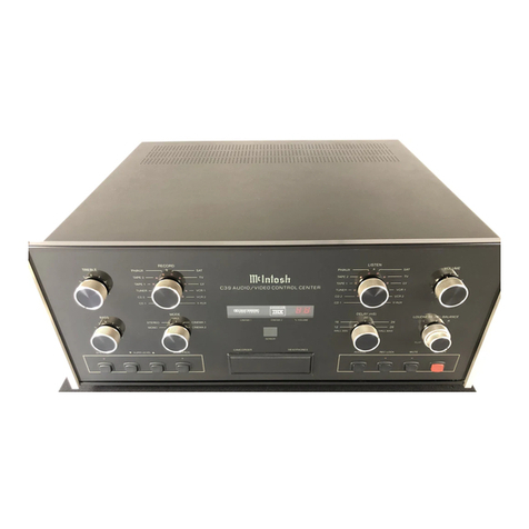
McIntosh C712 User manual

C712
SYSTEM
CONTROL
CENTER


C712
SYSTEM
CONTROL
CENTER

IMPORTANT
SAFETY
INSTRUCTIONS
THESE
INSTRUCTIONS
ARETO
PROTECT
YOUANDTHE
MclNTOSH
INSTRUMENT.BE
SURETO
FAMILIARIZE
YOURSELFWITH
THEM.
Copyright©1997by
MclntoshLaboratory,Inc.
1.Readallinstructions- Readthesafetyandoperatinginstructionsbefore
operatingtheinstrument.
2.RetainInstructions- Retainthesafetyandoperatinginstructionsforfuture
reference.
3.Heedwarnings- Adheretowarningsandoperatinginstructions.
4.FollowInstructions- Followalloperatinganduseinstructions.
WARNING:TOREDUCERISKOFFIREORELECTRICALSHOCK,DONOT
EXPOSETHISINSTRUMENTTORAINORMOISTURE.
5.PowerSources- Connectthepowersupplyonlytothetypedescribedinthe
operatinginstructionsorasmarkedontheunit.
6.PowerCordProtection- Routepowersupplycordssothattheyarenotlikelyto
bewalkedonorpinchedbyitemsplaceduponoragainstthem,payingparticular
attentiontocordsatplugs,conveniencereceptacles,andthepointwheretheyexit
fromtheinstrument.
7.Ventilation- Locatetheinstrumentforproperventilation.Forexample,the
instrumentshouldnotbeplacedona bed,sofa,rug,orsimilarsurfacethatmay
blockventilationopenings;or,placedina built-ininstallation,suchasa bookcaseor
cabinet,thatmayimpedetheflowofairthroughtheventilationopenings.
8.Heat- Locatetheinstrumentawayfromheatsourcessuchasradiators,heat
registers,stoves,orotherappliance(includingamplifiers)thatproduceheat.
9.WallorCabinetMounting- Mounttheinstrumentina wallorcabinetonlyas
describedintheowner'smanual.
10.WaterandMoisture- Donotusetheinstrumentnearwater- forexample,neara
bathtub,washbowl,kitchensink,laundrytub,ina wetbasementorneara swimming
pool,etc.
11.Cleaning- Cleantheinstrumentbydustingwitha drycloth.Cleanthepanelwith
aclothmoistenedwitha windowcleaner.
12.ObjectandLiquidEntry- Donotpermitobjectstofallandliquidstospillintothe
instrumentthroughenclosureopenings.
13.NonusePeriods- UnplugthepowercordfromtheACpoweroutletwhenleft
unusedfora longperiodoftime.
14.DamageRequiringService- Servicemustbeperformedbyqualifiedservice
personnelwhen:
A.Thepowersupplycordortheplughasbeendamaged;or
B.Objectshavefallen,orliquidhasbeenspilledintotheinstrument;or
C.Theinstrumenthasbeenexposedtorain;or
D.Theinstrumentdoesnotappeartooperatenormallyorexhibitsa marked
changeinperformanceor
E.Theinstrumenthasbeendropped,ortheenclosuredamaged.
15.Servicing- Donotattempttoservicebeyondthatdescribedintheoperating
instructions.Allotherserviceshouldbereferredtoqualifiedservicepersonnel.
16.GroundingorPolarization- Donotdefeattheinherentdesignfeaturesofthe
polarizedplug.Non-polarizedlinecordadapterswilldefeatthesafetyprovidedby
thepolarizedACplug.
2

17.
CAUTION:
TO
PREVENTELECTRICALSHOCK
DONOTUSE
THIS
(POLARIZED)PLUGWITHANEXTENSIONCORD,RECEPTACLEOROTHER
OUTLETUNLESSTHEBLADESCANBEFULLYINSERTEDTOPREVENT
BLADEEXPOSURE.
ATTENTION:
POURPEVENIR
LES
CHOCSELECRIQUES
PAS
UTILISER
CETTEFICHEPOLARISEEAVECUNPROLONGATEUR,UNEPRISEDE
COURANTOUUNEAUTRESORTIEDECOURANT,SAUFSILESLAMES
PEUVENTETREINSEREESA FONDSANSENLAISSERAUCUNEPARTIEA
DECOUVERT.
Thelightningflashwitharrowhead,withinanequilateraltriangle,is
intendedtoalerttheusertothepresenceofuninsulated"dangerous
voltage"withintheproduct'senclosurethatmaybeofsufficient
magnitudetoconstitutea riskofelectricshocktopersons.
CAUTION:
TO
PREVENT
THE
RISK
OF
ELECTRICSHOCK,DONOTREMOVECOVER(OR
BACK).NOUSER-SERVICEABLEPARTSINSIDE.
REFERSERVICINGTOQUALIFIEDPERSONNEL.
Theexclamationpointwithinanequilateraltriangleisintendedtoalert
theusertothepresenceofimportantoperatingandmaintenance
(servicing)instructionsintheliteratureaccompanyingtheappliance.
WARNING:THISUNITISCAPABLEOFPRODUCINGHIGH
SOUNDPRESSURELEVELS.CONTINUEDEXPOSURETO
HIGHSOUNDPRESSURELEVELSCANCAUSE
PERMANENTHEARINGIMPAIRMENTORLOSS.USER
CAUTIONISADVISEDANDEARPROTECTIONIS
RECOMMENDEDWHENPLAYINGATHIGHVOLUMES.
IMPORTANT
SAFETY
INSTRUCTIONS
THESE
INSTRUCTIONS
ARETO
PROTECT
YOUANDTHE
MclNTOSH
INSTRUMENT.BE
SURETO
FAMILIARIZE
YOURSELFWITH
THEM.
LIGHTNING- Foraddedprotectionforthisproductduringa lightningstorm,orwhen
itisleftunattendedandunusedforlongperiodsoftime,unplugitfromthewalloutlet
anddisconnecttheantennaorcablesystem.Thiswillpreventdamagetothe
productduetolightningorpowerlinesurges.
OVERLOADING- Donotoverloadwalloutlets,extensioncordsorintegral
conveniencereceptaclesasthiscanresultina riskoffireorelectricshock.
REPLACEMENTPARTS- Whenreplacementpartsarerequired,besuretheservice
technicianhasusedreplacementpartsspecifiedbythemanufacturerorhavethe
samecharacteristicsastheoriginalpart.Unauthorizedsubstitutionsmayresultin
fire,electricshock,orotherhazards.
SAFETYCHECK- Uponcompletionofanyserviceorrepairstothisproduct,askthe
servicetechniciantoperformsafetycheckstodeterminethattheproductisinproper
operatingcondition.
RISKOFELECTRICSHOCK
DONOTOPEN
CAUTION
3

THANK
YOU
YourdecisiontoownthispieceofMclntoshStereoEquipmentranksyouatthe
verytopamongdiscriminatingmusiclisteners.Younowhave"TheBest".The
Mclntoshdedicationto"Quality",isassurancethatyouwillreceivethousandsof
yearsofmusicalenjoymentfromthisunit.
Pleasetakea shorttimetoreadtheinformationinthismanual.Wewantyoutobe
asfamiliaraspossiblewithallthefeaturesandfunctionsofyournewpieceof
Mclntosh.Thiswillensurethatyoureceivealltheperformancebenefitsthis
instrumentcanofferyou,andthatitwillbecomea highlyvaluedpartofyourhome
musicsystem.
Theserialnumberandpurchasedateareimportanttoyouforpossibleinsurance
claimorfutureservice.Recordthisinformationhere.
SerialNumberPurchaseDate
INTRODUCTION5
HOWTOINSTALLTHEC7125,6
FRONTPANELCONTROLS,SWITCHESANDPUSHBUTTONS6,7
REARPANELANDHOWTOMAKECONNECTIONS7 -10
C712HANDHELDREMOTECONTROLLER10-12
SPECIFICATIONS12
CUSTOMINSTALLATIONDRAWING13
FOLDOUTDRAWINGSOFFRONTANDBACKPANEL.........14
TABLEOF
CONTENTS
4

Mclntoshhasearnedworldrenownforitstechnicalcontributionstoimprovedsound
reproduction.WhenyouboughtMclntosh,youboughtnotonlyhightechnology,butalso
technologicalintegrityprovenbytime.TheMclntoshC712SystemControlCenterisanother
exampleofMclntoshengineeringexcellence.
Mclntoshaudioproductsarealwaysdesignedforthebestsoundandsuperiorreliability.
Dedicationtoachievingthesegoalssince1949,hasearnedMclntoshthereputationfor
creatingthefinestqualityproductsinthestereoindustry.TheMclntosh"Classic"design
hasalsobeenrecognizedasthemostoutstandingintheindustry.
Mclntoshproductsaredesignedtobemaximumuserfriendlysoanyonecanenjoyusing
them.AnotherMclntoshdesignpolicyistoprovideproductsthatareeasytomaintain.
TheC712SystemControlCenterissimple,yetelegant.Therearemanyusefulfeatures
toenhanceyourlisteningenjoyment.TheC712isfullyremotecontrolledandalloperating
functionscanbeperformed atthefrontpanel,fromtheHandHeldRemoteControllerorfrom
awallmountedKeypad.
Therearesevenpairsofhighlevelinputstoaccommodatethetraditionalprogramsources
aswellasthemostrecentnewsources.TheseincludeCDplayers,audiosignalsfromlaser
discplayersandaudiofromvideorecorders.A PHONOinputisalsoprovidedfora record
playerwitha magneticphonocartridge.IfthePHONOisnotused,theAUXinputcanaccom-
modateanotherhigh-levelprogramsource.
DIGITALLOGICintegratedcircuitsdriveELECTROMAGNETICSWITCHESonallinputsand
operatingfunctionsforthemostreliable,lowestdistortionswitchingavailabletoday.
TwoTAPEMONITORswitchesallowtheuseoftwoseparatetaperecorders.TwoTAPECOPY
switchesarealsoprovidedforeasytapecopyingfromonerecordertotheother.A continuously
variableActiveLoudnesscontrolallowsloudnesscompensationtobeselectedforanyset-
tingofthevolumecontrol.TheLoudnesscontrolcircuitelementsareremovedfromthesignal
pathwhenthecontrolisintheflatorfullycounterclockwiseposition.
BassandTrebletonecontrolsprovide12dBofboostorcut.Atthecenterordetentposition
ofthetonecontrols,alltonecontrolcircuitsareremovedfromthesignalpath.Otherfeatures
includea frontpanelHeadphoneoutput,a MonoswitchandrearpanelSignalProcessorLoop
connectionsthataffectthemainoutputs.Powersupplyvoltageregulatorcircuitsmaintain
stableoperationeventhoughtheACpowerlinemayvary.Adoubleshieldedpowertransformer
completelyisolatesitfromtheaudiocircuits.
ApairofBalancedOutputsisalsoincludedtotakeadvantageofthegreaternoisereduc-
tioncapabilitiesofbalancedcables.
TheC712canbeplaceduprightona tableorshelf,standingonitsownplasticfeet.It
alsocanbeinstalledinanoptionalMclntoshL70equipmentcabinet.Followthemounting
instructionsenclosedwiththeL70cabinet.
TheC712alsocanbecustominstalledina pieceoffurnitureorcabinetofyourchoice.
Therequiredpanelcutoutandunitdimensionsareshownona pagefurtherbackinthismanual.
AlwaysprovideadequateventilationforyourC712,eventhoughitdevelopsverylittleheat.
Cooloperationinsuresthelongestpossibleoperatinglifeforanyelectronicinstrument.Do
notinstallyourC712directlyabovea heatgeneratingcomponentsuchasa highpowered
amplifier.Ina systemstack,thepoweramplifiershouldalwaysbeatthetop.Ifallthecom-
onentsareinstalledina singlecabinet,a quietrunningventilationfancanbea definiteasset
INTRODUCTION
HOWTO
INSTALL
THE
C712
5

HOWTO
INSTALL
THE
C712
inmaintainingallthesystemcomponentsatthecoolestpossibleoperatingtemperatures.
Acustomcabinetinstallationshouldprovidethefollowingrecommendedminimumspac-
ingdimensionsforcooloperation.Allowatleast1-1/2inches(3.8cm)abovetheunitsoairflow
isnotobstructed.Allow17-1/2inches(44.5cm)depthbehindthemountingpanel,whichin-
cludesclearanceforconnectors.Allow1-1/8inches(2.9cm)infrontofthemountingpanel
forknobclearance.
The last page of this manual folds out to show photographs of the front and rear
panels of the C712. This will help you in identifying and locating the controls and
switches on the C712 front panel, and the connectors on the rear panel. The letters
and numbers on the photographs refer to the paragraphs that follow.
A.INPUT
SelectstheprogramsourcethatfeedstheMAINBALANCED,UNBALANCED,TAPE1 and
TAPE2 OUTPUTS.
B.BASSandTREBLE
Provide12dBBoostorCutwithflatresponseatthecenterdetentposition.Alltonecontrol
circuitelementsareremovedfromthesignalpathinthecenterflatposition.
C.BALANCE
TheBALANCEcontroladjuststhevolumeofthechannelsrelativetoeachother.
L,(left):Turnthecontroltothelefttoaccenttheleftchannelbyreducingthevolumeof
therightchannel.
R,(right):Turntherighttoaccenttherightchannelbyreducingthevolumeintheleftchannel.
D.LOUDNESS
TheLOUDNESScontrolprovidesfrequencyresponsecontouredtocompensateforthe
behaviorofthehumanearatsofterlisteninglevels.Atthefullycounterclockwisedetentposi-
tion,thefrequencyresponseisperfectlyflatandtheloudnesscircuitcomponentsareremoved
fromthesignalpath.Turnthecontrolclockwisetoincreasefrequencycompensationinthe
correctproportionforproperlisteningatsoftervolumelevels.Thecompensatedfrequency
responseisnotaffectedbychangesinthevolumecontrolsettings.Firstadjustthevolume
forthedesiredlisteninglevel,thenadjusttheloudnesscontroltothesettingyouprefer.
E.IRSENSORWINDOW
TheIR(Infrared)sensorthatacceptsIRsignalsfromtheC712HandHeldRemoteController.
RVOLUME
AdjuststheVolumelevelfromtheMAINBALANCEDandUNBALANCEDOUTPUTS.The
TAPEOUTPUTSarenotaffectedbytheVOLUMEcontrol.
G.MONO
PresstheMONOpushbuttontoaddtheleftandrightchannelsignalstogetherforMONO
signalsattheMAINBALANCEDandUNBALANCEDOUTPUTS.ARedLEDabovethepushbut-
tonwilllighttoindicatetheMONOmodeofoperation.TheMONOpushbuttondoesnotaffect
theTAPEoutputs.Theyarealwaysstereo.
H.TAPEMONitor1 and2
PressTAPEMON1 or2 tolistentoplaybackoftapesfromeitheroftwotaperecorders.
FRONTPANEL
CONTROLS,
SWITCHES
AND
PUSHBUTTONS
6

Youcanlistentopreviouslyrecordedtapes,ormonitortapefroma three-headtaperecorder
duringtherecordingprocess.TheTAPEMONpushbuttonsoperateindependentlyfromthe
INPUTswitch.A RedLEDwilllightaboveeitherpushbuttontoindicatewhichTAPEMONhas
beenselected.
I.HEADPHONES
Plugina pairoflowimpedancedynamicheadphonestothisjackforheadphonelistening.
PressMUTEontheC712RemoteControllertomutethemainoutputstothepoweramplifier
toallowprivateheadphonelistening.MUTEdoesnotaffecttheHeadphonesOutput.
J.TAPECOPY,1 2,21
Copytapesfromeitheroftwotaperecorders,toeachother.TheTAPECOPYpushbutton
switchesoperateindependentlyfromtheINPUTswitch.UsetheTAPEMONitorswitchesto
monitortheoutputoftherecorderplayingtheoriginaltape,ortherecordermakingthecopy.
ARedLEDwilllightaboveeitherpushbuttontoindicatewhichTAPECOPYmodeisinuse.
TheTAPECOPYswitchesareelectronicallyinterconnectedtopreventbothcircuitsfrom
beingactivatedatthesametime.IfyoupressoneoftheTAPECOPYswitchestoactivate
acopyfunction,youmustpressthesameTAPECOPYswitchagainbeforepressingtheother
TAPECOPYswitch.
K.POWER
PresstheredPOWERbuttontoturntheC712systemON.PressagaintoturnitOFF.The
rearpanelSWITCHEDACOutletturnsonwiththePOWERswitch.
FRONTPANEL
CONTROLS,
SWITCHES
AND
PUSHBUTTONS
Usegoodqualityshieldedcablestointerconnecttheassociatedequipmentusedwiththe
C712.Theinstallationofhighqualitycableswillinsurethebestpossibleperformancefrom
yourstereosystem.YourMclntoshdealercanadviseyouonthetypeandlengthofcables
bestsuitedforyourinstallation.
1.SWITCHEDACOUTLET
TheSWITCHEDACoutletturnsonandoffwiththefrontpanelPOWERSwitch.Connect
apoweramplifieroraccessoriestothisoutlet.
ThetotalpowercapacityoftheSWITCHEDACoutletmustnotexceed1400watts
or11.6amperes.
ToexpandtheACcapacityoftheSWITCHEDoutlet,adda MclntoshR612AorPC2Power
Controller.
2.L andR BALANCEDOUTPUTS
ConnectcableswithXLRtypeBalancedConnectorsfromtheC712,L (Left)andR (Right)
BALANCEDOUTPUTjackstothebalancedinputjacksofa stereoamplifier,ortwomonoamp-
lifiers.SignalsattheBALANCEDjacksarethesamesignalsasattheUnbalancedMAINOUTPUTS.
Usingbalancedconnectorsandcablescanreducenoiseandinterferencebyasmuchas
40dB.Thisextranoisereductioncanbea significantimprovement,especiallyifthecables
arequitelong.Iftwoseparatemonopoweramplifiersareusedwith theC712,balancedcables
caneliminatethepossibilityofhumpickup.IfcablelengthsbetweentheC712andthepower
amplifiersareonemeterorless,youmayfindhighqualityunbalancedcablestobeadequate.
BalancedJackPinConfiguration:
Pin1.SystemGround
Pin2.+ Output
Pin3.- Output
THEREARPANEL
ANDHOW
TOMAKE
CONNECTIONS
7

THEREARPANEL
ANDHOW
TOMAKE
CONNECTIONS
3.MAINOUTPUTS(Unbalanced)
ConnectshieldedcablesfromtheC712MAINL andR OUTPUTStotheLeftandRight
channelpoweramplifierinputs.
4.TAPEOUTPUTS1 and2
Theseoutputsprovidesignalstofeedtwoseparatetaperecorders.Theprogramthatap-
pearsatthetapeoutputsisdeterminedbythesettingofthefrontpanelINPUTswitch.The
TAPECOPYSwitchalsoaffectsthesignalsatthetapeoutputs.
Connecta cablefromtheC712LeftchannelTAPE1 OUTPUTtotheleftchannelhighlevel
inputofa taperecorder.Connecta cablefromtheC712RightchannelTAPE1 OUTPUTto
therightchannelhighlevelinputofthetaperecorder.Connecta secondtaperecorderin
asimilarmanner,totheTAPE2 OUTPUTS.
If more than one tape recorder is connected for both record and play, make certain
that the inputs and outputs of each recorder are connected to the same matching
numbered inputs and outputs.
5.PROCESSORFROMandTO
AnexternalsignalprocessorcanbeaddedtotheC712thatwillaffectonlytheMAINand
BALANCEDOutputs.
ThePROCESSOR-FROMjackshavebuilt-inswitchingcontactstoallownormalsignalsto
passthroughwhennocablesareconnected.Whenanexternalprocessorisproperlycon-
nected,theprogramsignalsfeedtotheprocessorfromthePROCESSOR-TOjacks,andreturn
totheC712atthePROCESSOR-FROMjacks.
Connecta cablefromtheleftchannelprocessoroutputtotheC712leftchannel
PROCESSOR-FROMjack.Connecta cablefromtherightchannelsignaloutputtotheC712
rightchannelPROCESSOR-FROMjack.
Connecta cablefromtheC712leftchannelPROCESSOR-TOjacktothesignalprocessor
leftchannelinput.Connecta cablefromtheC712rightchannelPROCESSOR-TOjacktothe
rightchannelsignalprocessorinput.
WHEN AN EXTERNAL SIGNAL PROCESSOR IS CONNECTED TO THE C712 PRO-
CESSOR JACKS, THE PROCESSOR MUST BE TURNED ON AND OPERATING, OR IN
BYPASS MODE, FOR A PROGRAM TO BE HEARD THROUGH THE SYSTEM.
6.TAPES1 and2
Connecta cablefromtheleftchanneloutputofa taperecordertotheC712L(Left)channel
TAPE1 or2 INPUT.Connecta cablefromtherightchanneloutputtothecorrespondingR
(Right)TAPE1 or2 INPUT.Connecta secondtaperecorderina similarmanner.
TheTAPEINPUTScanalsobeusedforotheraccessoryequipmentwithsimilaroutputlevels.
IF MORE THAN ONE TAPE RECORDER IS CONNECTED TO BOTH RECORD AND PLAY,
MAKE CERTAIN THAT THE INPUTS AND OUTPUTS OF EACH RECORDER ARE CON-
NECTED TO THE SAME MATCHING NUMBERED INPUTS AND OUTPUTS.
7.VIDEO
Usetheseinputsfortheaudiosignalsfromaccessoriessuchasa LaserDiscPlayer,VCR,
orTVreceiver.
Connecta cablefromtheleftchannelaudiooutputofthevideounittotheC712L (Left)
channelVIDEOINPUT.Connecta cablefromtherightchannelaudiooutputtotheC712R
(Right)VIDEOINPUT.UsetheVIDEOinputwhenanoptionalMVS-3Audio/VideoSwitcher
8

isaddedtotheC712fortheadditionofvideoswitching.TheMVS-3mustalsobeconnected
totheC712VIDEODATAPORT.
8.TUNER
Connectcablesfromtheleftandrightchanneloutputsofa tunertotheC712L (Left)and
R(Right)TUNERINPUTS.
9.CD1andCD2
Connecta cablefromtheleftchanneloutputofa CDplayertotheC712L (Left)CD1IN-
PUT.ConnectacablefromtherightchanneloutputtotheC712R (Right)CD1INPUT.Con-
necta secondCDplayertotheC712CD2inputsina similarmanner.
Forexample,CD1inputscouldbeusedfora singleplayCDplayer,andtheCD2inputs
fora CDchanger.
10.AUX(Auxiliary)/ PH(Phono)
BoththePHonoandAuxiliaryinputjacksareselectedbythesamepositiononthefront
panelINPUTswitch.Oneortheotherpairofinputscanbeused,butnotbothsimultaneously.
ConnecttheleftchannelhighleveloutputofanyaudioaccessoryunittotheC712,L(Left)
AuxiliaryINPUT.ConnecttherightchannelaccessoryoutputtotheC712,R (Right)Auxiliary
INPUT.WhencablesareconnectedtotheAUXinputjacks,thePHonocircuitisautomatical-
lybypassed.
Toconnectarecordplayerwithamagneticphonocartridge,FIRST,removeanycon-
nectingcablesfromtheAuxiliaryinputjacks.
Connecta cablefromtheleftchannelturntableoutputtotheC712L (Left)PHonoINPUT.
Connecta cablefromtherightchanneltotheC712R (Right)PHonoINPUT.
TheC712phonoinputcircuitisdesignedtoacceptthesignalsfroma standardmoving
magnetphonocartridge.
11.ACPOWER
ConnecttheACPowercabletoa live120volt50/60HzACoutlet.
The plug blades are polarized so be certain the plug is fully inserted in the outlet to
preventblade exposure.
CAUTION:TOPREVENTELECTRICSHOCK,DONOTCONNECTTHEPOLARIZEDAC
PLUGONTHISUNITTOANEXTENSIONCORDOROTHERACOUTLETTHATISNOT
DESIGNEDTOACCEPTPOLARIZEDPLUGS.THEPLUGMUSTBEFULLYINSERTED
TOPREVENTBLADEEXPOSUREANDMAINTAINLINEPOLARITY.
12.EXTernalSENSOR
Connecta coaxialcablefromtheEXTernalSENSORconnectortoanR649WallIRSensor,
aWK-1orWK-2Keypad.ThisallowstheC712handheldremotecontrollertosendcontrol
signalstotheC712withoutaimingitattheC712frontpanel.Anexamplewouldbeifthe
C712wereinstalledbehinda cabinetdoorthatwouldblockthefrontpanelsensor.
13.TUNERCONTROL
Connecta MclntoshW102TunerControlCablefromtheTUNERCONTROLconnectorto
aconnectorona compatibleMclntoshtunersuchastheMR7083.Thisallowsyoutoselect
andcontroltuneroperatingfunctionswiththeC712handheldremotecontrollertransmitting
toa C712IRsensor.
14.CD1/CD2CONTROL
Connecta MclntoshModelW101CDcontrolcablefromtheCD1orCD2CONTROLcon-
THEREARPANEL
ANDHOW
TOMAKE
CONNECTIONS
9

THEREARPANEL
ANDHOW
TOMAKE
CONNECTIONS
nectortoa matchingconnectorona MclntoshCDplayerorchanger.Thisallowsyou
tocontrolCDplayerfunctionswiththeC712remotecontrollertransmittingtoa C712
IRsensor.YoucoulduseCD1fora singleplayCDplayerandCD2fora CDchanger.
15.POWERCONTROL
Thisconnectorsuppliesa5 volt,DCLogic1 controlsignaltofeed toa similarPower
Controlinputona compatiblepoweramplifieroraccessory.ThePOWERCONTROL
signalisusedtoturntheACpoweroftheaccessorycomponentonandoff.
ThePOWERCONTROLconnectorusessingleconductorshieldedwirewith1/8
inchminiPhonoplugs.Connectionsaretothetopandsleeveoftheplug.
16.DATAPORTS
TheeightDATAPORTSprovidedatasignalstobefedtocompatibleaudioand
videoaccessories.Thisallowsyoutocontroltheaccessorycomponentswiththeir
ownremotecontrollerstransmittingtoa C712IRsensor.
TheSUMDATAPORTcanbeusedtoconnecttoa MclntoshRCT-2Remote
ControlTranslator.AnyIRsignaltransmittedtoa C712IRsensorresultsindata
signalsatthisport.TheRCT-2isa learningdevicethatwillallowtheC712to
remotelycontrolmostmajorbrandsofaccessorycomponents.
UsetheVIDEODATAPORTtoconnecttotheMVS-3AudioVideoSwitcher.
Allcablesconnectedfromthedataportsuseshieldedwirewith1/8"miniphone
plugs.Connectionsaretothesleeveandtipoftheplug.
17.GND(Ground).
Ifthereisa separategroundwirefromtheturntable,connectittotheGNDterminal.
C712HANDHELD
REMOTE
CONTROLLER
ThedescriptionsandfunctionsoftheC712RemoteControllerpushbuttonsreferto
thenumbersonthedrawing.
SPECIAL NOTE: The pushbuttons marked in black do not function with the
C712. They function only when this Remote Controller is used with another
Mclntosh model.
1.CD1,CD2,TUNER,PH/AUXANDVIDEO
SelectinputsignalsforCD1,CD2,TUNER,PHono/AuxorVIDEO.
2.LS/TM1,LS/TM2
PressLS/TM1,(TAPEMONITOR1),orLS/TM2,(TAPEMONITOR2)tolistento
playbackoftapesfromeitheroftwotaperecorders.Youcanlistentopreviously
recordedtapes,ormonitortapefroma threeheadtaperecorderduringthe
recordingprocess.A RedLEDwillturnONabovetheC712frontpanelpushbutton
markedTAPEMON1 orTAPEMON2.toindicatewhichisselected.TheTAPE
MONITORinputscanalsobeusedforanysimilarhighlevelsignalsourcesuchasa
tunerorCDplayer.
3.TV,LV,VCR1,VCR2andV/AUX
SelectadditionalAudiovideoprogramsourceswhentheoptionalMVS-3
Audio/VideoSelectorisaddedtotheC712.FirstpresstheVIDEOpushbuttonand
thenthedesiredpushbuttonforanyofthefivesourcesthatcanbeselectedbythe
MSV-3.
4.CD/TAPE
SelectCDplayer,CDChangerortaperecorderfunctions.
10

Usinga MclntoshSINGLEDISCCD
PLAYER,STOP,BACKTRACKNEXT
TRACKandPLAYfunctionscanbe
performed.
Usinga MclntoshCDCHANGER,STOP,
BACKTRACK
NEXTTRACK
and
PLAYfunctionscanbeperformedwhilea
discisplaying.
WhentheCDchangerisintheSTOP
position,BACKTRACKselectsthe
SINGLEDISCandNEXTTRACKselects
whichoftheothersixdiscsyouwishtoplay.
AfterpressingSTOP,thefirsttimeyoupress
NEXTdiscnumber1 isselected.Press
againasdesiredtoselectdiscs2 through
6.
FOREXAMPLE:Toselectdiscnumber6
fromthesinglediscplaymode,press
STOPandthenNEXTsixtimes.To
selectdiscnumber2,pressSTOPandthen
pressNEXTtwice.ToselectthediscintheSINGLEdiscslot,pressSTOPand
thenpressBACKonce.
5.POWER
PressthePOWERpushbuttontoturntheC712systemonoroff.
6.ACC
OFF,
ACCON
TheACC(Accessory)OnorOFFpushbuttonsfunctionwhentheoptionalRCT-2
RemoteControlTranslatorisbeingusedwiththeC712.Theycanbeprogrammedto
turntheACpowerofanaccessorycomponentonoroff.
(Pushbuttons listed under Number 7 and Number 8 function when a
compatible Mclntosh Tuner is connected to the C712.)
7.0 through9
PressoneofthenumberedpushbuttonstoselectTunerStationpresets.
8.AM,FM,REVIEWandSEEK
SelecttheTunerfunctionsAM,FM,REVIEW,SEEKUPorSEEKDOWN.
9.E
E(ENTER)isusedwiththeoptionalRCT-2RemoteControlTranslatortooperate
accessoryequipment.
10.MUTE
PressMUTEtomuteallaudiooutputsexceptthoseforHeadphonesandTape.A
RedLEDabovethefrontpanelvolumecontrolturnsONtoindicatethattheoutputs
aremuted.PressMUTEa secondtimetorestorenormaloperation.
11.VOLUME
Press(UP)VOLUMEtoraisethelisteningvolumeand(DOWN)VOLUMEto
lowerthelisteningvolume.TheTapeOutputsarenotaffectedbytheremote
VOLUMEpushbuttons.
C712HANDHELD
REMOTE
CONTROLLER
11

C712HANDHELD
REMOTE
CONTROLLER
HOWTOINSTALLBATTERIESINTHEC712HANDHELDREMOTECONTROLLER
Slideopenthebatterycompartment.InserttwotypeAAAbatteriesintothe
compartment,makingsuretoobservethebatterypolaritiesindicatedinthebattery
compartment.
Whenthebatteriesarenearingexhaustion,theeffectiverangeoftheremote
controllerdecreases,andMAYevenfailtooperate.Inthiscase,replaceboth
batterieswithfreshones.
NOTE:
1.Donotmixoldandnewbatteries.UseONLYbatteriesthatarenew.
2.Makesurebothbatteriesareofthesametypeandidentical.
3.Topreventdamagecausedbypossiblebatteryleakage,removethebatteriesfrom
theremotecontrollerifitisnotgoingtobeusedforanextendedperiodoftime.
4.Neverdismantlebatteriesordisposeofthemina fire,astheymayexplode.
Disposeofoldbatteriesinanapprovedmethodforpropersafety.
SPECIFICATIONS
FRQUENCYRESPONSE
+0,-0.5dBfrom20Hzto20,000Hz
RATEDOUTPUT
2.5VatBALANCEDandMAIN
(Unbalanced)OUTPUTS
MAXIMUMVOLTAGEOUTPUT
8Vfrom20Hzto20,000Hzat
BALANCEDandMAIN(Unbalanced)
OUTPUTS.
TOTALHARMONICDISTORTION
0.002%maximumfrom20Hzto
20,000Hzatratedoutput.
SENSITIVITY
Phono:2.5mVfor2.5Vratedoutput,
(0.5mVIHF).
HighLevel:250mVfor2.5Vrated
output,(50mVIHF).
SIGNAL-TO-NOISERATIO,
A-Weighted
Phono:90dBbelow10mVinput,(84dB
IHF).
HighLevel:105dBbelowratedoutput,
(95dBIHF).
MAXIMUMINPUTSIGNAL
Phono:90mV
HighLevel:10V
INPUTIMPEDANCE
Phono:47Kohmsand65pFCapacitance
HighLevel:22Kohms
VOLTAGEGAIN
PhonotoTape:40dB
PhonotoMain:60dB
HighLeveltoTape:0dB
HighLeveltoMain:20dB
TONECONTROLS
BassandTreble,variable12dBboost
to
12dBcut.
ACPOWEROUTLET
OneSwitched;Totalcurrentcapacity
11.6amperes,(1400watts)
MECHANICAL
SIZE
FrontPanelmeasures17-1/2inches
(44.5cm)wideby3-5/8inches(9.2cm)
high.Chassisdepthbehindthemounting
panelincludingclearanceforconnectors
is17-1/2inches(44.5cm).Knob
clearancerequiredinfrontofmounting
panelis1-1/8inches(2.9cm).
FINISH
FrontPanelisglasswithgold/teal
nomenclatureillumination.Thechassisis
black.
WEIGHT
17lbs.(7.7Kg)net,29Ibs.(13.2Kg)in
shippingcarton.
12

CUSTOM
INSTALLATION
DRAWING
13


Thelettersandnumberscorrespondtotheparagraphsonpages7,8,9,and10.

04050400
BE012003


Table of contents
Other McIntosh Control Unit manuals
Popular Control Unit manuals by other brands

Farris Engineering
Farris Engineering Curtiss-Wright 2600 Series Maintenance manual

Samsung
Samsung CCBQ730M user manual

ICP DAS USA
ICP DAS USA PROFIBUS PROFI-2510 quick start

Texas Instruments
Texas Instruments UCC2 5 EVM-286 Series user guide

Evco
Evco EVBOX1 EVB1204 installation guide

Honeywell
Honeywell SM152 AA Series installation instructions

AAON
AAON PREHEAT-X Technical guide

Burkert
Burkert 5282 operating instructions

Texas Instruments
Texas Instruments BoosterPack BP-ADS7128 user guide

GEM
GEM 761 Installation, operating and maintenance instructions

Grundfos
Grundfos BMS Series Service instructions

Siemens
Siemens 3VL92 Series operating instructions