micro-trak 8000 FA User manual

MICRO-TRAK 8000 FA MANUAL VER 2.0
The Micro-Trak 8000 FA is a frequency agile and programmable miniature APRS (Automatic Position
Reporting System) transmitter capable of operating from 144 to 148 MHz. (foreign and gornmental agencies
may contact us to discuss out of band operation, but the Micro-Trak products are not FCC certified for use
outside the ham bands in the United States) The transmitter utilizes a special version of the TinyTrak3
controller and is not compatible with any other version of TinyTrak firmware or config software. The entire
assembly measures only 1 X 4.5 inches, and weighs less than two ounces. The Micro-Trak 8000 FA is a
creation of VHS Products, and is distributed exclusively by Byonics at http://www.byonics.com
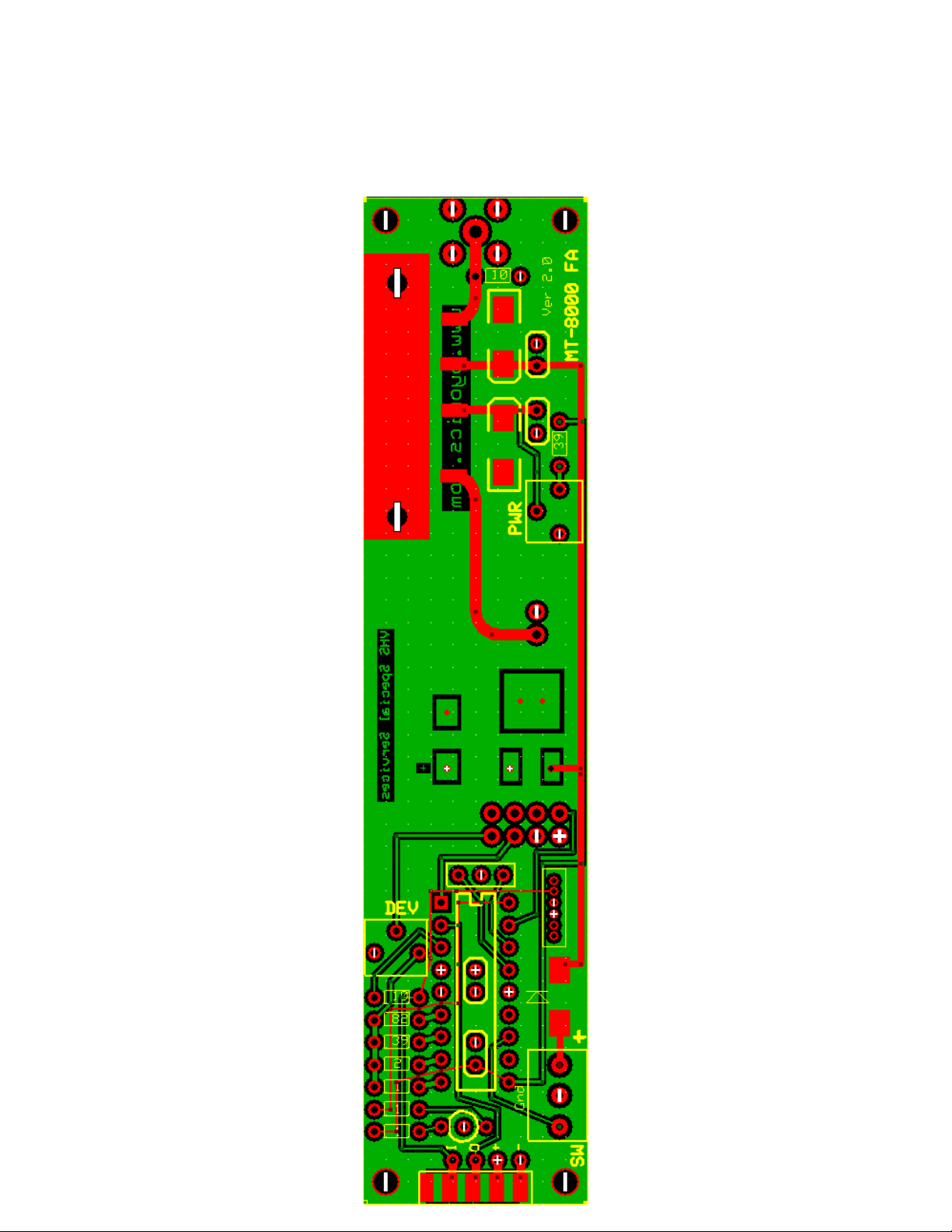
The MT-8000 FA is extremely compact
and light, due in part to the enclosed RF
section. The Micro-Trak 8000 FA is
provided as a fully assembled and
populated printed circuit board assembly.
Completion and operation of the device
will require simple programming, and
providing power, antenna, and a GPS
input. The Micro-Trak 8000 FA is shipped
wired and tested, but should be adjusted
by the user for the desired output power.
The power output may be adjusted with a trimmer potentiometer located on the printed circuit board’s amplifier
section. This version of the Micro-Trak 8000 FA has been provided with an external, user adjustable deviation
control, which should ordinarily be left rotated completely clockwise. Certain areas (Europe, etc.) may have
digipeaters that prefer a slightly more narrow-band deviation level. Using a receiver, you can set your deviation
level to the approximate deviation of users in your area.
Because of its small size and light weight, the MT-8000 FA is ideal for portable and airborne operations. Small
size not withstanding, the Micro-Trak 8000 FA is capable of power output in excess of 8 Watts, and is capable
of operating at extremely long ranges. An on-board 5 volt regulator provides an optional 200 mA, power output
for your GPS receiver. (Many applications, including the use of the device with hand-held GPS units, will not
require the 5 volt output of the Micro-Track.) The entire system runs well on 9-13.2 volts DC, and draws only
about 15 milliamps in standby, and increases to 1.7 amperes during transmissions (which last approximately
1/3 of a second using MIC-E) when set for full power operation. The Micro-Trak 8000 has easily adjustable
power settings for responsible and energy saving operation. The Micro-Trak utilizes a combination green/red
LED: green LED for the green GPS detector light and red LED transmit light.
No case or package is provided with the Micro-Trak 8000 FA, allowing the user to package the device
according to their own unique needs. The design philosophy called for as small, light and basic a package as
possible, with a high enough output for more critical and remote operations. The programming and GPS input
connection is set up to use a DB9 Male connector (The same as a standard TinyTrak 3) by simply sliding the
connector over the tabs, soldering may be required for a good connection. The Micro-Trak can connect to a
standard GPS receiver directly through the DB9 connector, but it is important to remember that computer
programming and communication uses a reversed connection, meaning you will need a female to female null
modem cable, or a null modem adaptor and a gender-changer connector for programming your Micro-Trak.
These cables and/or connectors are available from Byonics. A 6 pin 1 mm style connector is mounted on the

board, which will provide plug and play operation with a Byonics GPS 3. You must disconnect the GPS during
programming, as the redundant load across the serial input will prevent programming. The GPS is powered by
the transmitter, and power to the GPS is not switched.
Download the Micro-Trak 8000 FA configuration program from the Byonics webpage. Previous versions of the
TT3 configuration software are not compatible with the Micro-Trak 8000 FA. Note that a unique frequency
may be programmed in each configuration screen as well as all the normal operating parameters. Configuration
selection is accomplished using an external switch. Each time the unit is powered on, the TT3 controller will
reprogram the transmitter with the current desired operating frequency and other programmed parameters,
including call sign, digipath, etc. Changing the configuration switch will also cause the TT3 PIC to reprogram
the transmitter.
The combination of the Micro-Trak 8000 FA and the special TinyTrak3 firmware produces a hybrid that is
capable of being adapted to virtually any portable APRS project. It is important to remember, that this is a
transmit-only system, and may transmit coincidentally with other APRS transmitters. Complete information
about TinyTrak and the Micro-Trak 8000 FA, Version 2.0, as
well as configuration software may be found at:
http://www.byonics.com/microtrak E-Mail information requests about all Micro-Trak products can be addressed
Safety
The Micro-Trak 8000 FA is not designed for 100 % duty cycle (continuous) operation. It is designed for
intermittent packets of data, as is typical in APRS operations. Use appropriate RF safety protocols when
operating this transmitter. Do not operate the device without having an antenna or RF dummy load
connected to the antenna output! Do not operate the device into very high SWR antenna connections.
This can destroy not only the amplifier module but the entire RF section of the Micro-Trak 8000, and will not
be serviced as a warranty repair. Contact with the device during transmissions may result in RF burns.
Terminal Input Block
Note that the Micro-Trak 8000 Version 2.0 has a screw terminal input block for power and configuration
switch input. The topmost screw, marked with a “+” is the DC positive input. The center screw is ground, and
the bottom screw, marked “SW” is the Configuration switch input. Note that this pin is switched to ground to
change configurations and frequencies. Take care not to connect the SW input to the positive supply line, as this
could damage or destroy your TT3 controller chip. Please note that the SW (switch) input is used only to select
one of two configurations with which you have previously programmed the unit. It is not used in any way
during computer programming of the Micro-Trak. A steering diode has been installed in this version which will
generally prevent damage to the unit from applying reverse polarity power.

MICRO-TRAK 8000 FA SCHEMATIC

Adjusting the amplifier stage
The amplifier section of the MT-8000 FA has only a single control, which is designed for infrequent
adjustment. Use an RF tuning tool or a small screwdriver for adjustments, being careful not to over rotate the ¼
inch trimmer potentiometer. Set the trimmer to center position. Make sure that you have connected a dummy
load, or at least an antenna, to the amplifier output before connecting power. For maximum power, the trimmer
is set fully clockwise.
Adjust the trimmer potentiometer on the Micro-Trak for your desired power output level, Note that all of the
power adjustment, from a few hundred milliwatts to up to 8 Watts, will be within only a few degrees of the
center position of the wiper arm. The power output is supply-voltage dependant, and you should adjust the
power output at your maximum intended voltage of operation. No retuning with frequency changes within the
specified bands is required. Note that higher power levels will of course result in higher power consumption,
and shorter battery life. Keep in mind that polite hams do not use more power than is necessary. One or two
watts output power is almost always enough if there is a Digipeater in your area. Excessive transmission
interval rates may cause the amplifier to overheat and be damaged. Keep transmission intervals rates long, and
packets short, and use minimum power for your application. Micro-Trak operators have reported ranges of 600
KM with 300 milliwatts from an altitude of 117,000 feet. It is possible to produce a higher output power by
removing the 3.9 K resistor connected to the power trimmer pot, and setting the trimmer control to provide no
more than 3 volts to the gate of the amplifier module. This procedure could potentially allow you to drive the
amplifier gate with up to 5 volts, which would destroy the amplifier in short order. Use only analog voltmeters
or oscilloscopes to set the gate voltage, as the response times of digital VOM’s is not sufficient to measure the
300ms gate turn-on pulse.
Operating Voltages
The Micro-Trak 8000 FA will run with reduced power at lower voltages, and should not be powered by
voltages exceeding 13.2 volts, including unregulated automotive voltages. Like all MOSFET devices, the
device can be damaged by static or high voltages, including static charges that may build up on mobile antennae
in thunderstorms or dry areas. Use static protection procedures on antennae other than portables whips. A static
“bleeder” resistor has been installed in this version of the Micro-Trak 8000 FA to prevent damage from external
static, but static or RF fields of very high power can still damage the amplifier module. The Micro-Trak FA
should be powered by a power supply or battery pack capable of producing 2.0 Amperes at 12 volts, but no
more than 13.2 volts. Higher voltages such as automotive or aircraft alternator voltages, will destroy the
amplifier module in short order. Byonics offers a regulated power supply (Micro-Volt 12) that will allow you to
run your MT-8000 FA from automotive level voltages.
Disclaimers
Thank you for purchasing the Micro-Trak 8000 FA! The Micro-Trak 8000 is intended for licensed ham radio
operators only. Other applications, while possible, may not be prudent given the absence of heat sinks on this
device. Power output may be different with a range of variables, and no particular power output is guaranteed.
Operating the amplifier for excessively long continuous periods, or into poorly matched antennae or other loads,
may destroy your module. MOSFET and RF modules will not be replaced under warranty, but replacement
parts will be available for nominal fees. This transmitter was designed for qualified radio technicians. RF safety
measures should always be paramount. Even 8 watts of RF power can cause damage under certain
circumstances. While the MT-8000 FA has been tested and confirmed working before shipping, you use it at

your own risk. VHS Products and Byonics are not responsible for any damage resulting from the use of this
device.
Printed Circuit Board Layout

Amplifier RF Module Equivalent Circuit
This circuit reflects the basic components of the MOSFET RF module used in the Micro-Trak 8000.
The pins shown are 1 through 5. Looking at the module from left to right, you will see pins 1 through 4, with
the metal case and mounting flanges represented by pin 5, Ground. The amplifier you will note uses band pass
filters internally to minimize any out of band signals. These filters effectively limit the spectrum of the amplifier
to ham and public service bands.
Block Diagram of Narrow Band FM Transmitter Module.
Block diagram of sealed RF Narrow band PLL Modulator. Note that the circuit uses a high quality crystal-
controlled design, and pays particular attention to input and output filtering for spectral purity.

MICRO-TRAK 8000 FA PROPRIETARY CONFIGURATION SOFTWARE
The configuration software for the MT-8000 FA appears to be very similar to the standard TinyTrak3 software,
but is not compatible. Note that this version has a field for setting the frequency of one of two channels. Any
frequency in the range of 144 to 148 MHz using 5 KHZ channel spacing may be programmed into the device.
The TT3 PIC stores the frequencies and other parameters in non-volatile memory, and reinitializes the
transmitter whenever it is switched on, and when the configuration switch is changed.
You may download the complete TinyTrak3 configuration manual from the Byonics website for additional
information. Please join the Micro-Trak Yahoo User’s group! http://groups.yahoo.com/group/MicroTrak/


Other micro-trak Control Unit manuals