McIntosh C8 - SCHEMATICS User manual

INSTRUCTIONMANUAL
MclNTOSHMODELC-8andC-8P
AUDIOCOMPENSATORS
McINTOSHLABORATORY,INC.
320WaterSt.Binghamton,N.Y.
U.S.A.

-1 -
INSTRUCTIONMANUAL
McINTOSHMODELC-8andC-8P
AUDIOCOMPENSATORS
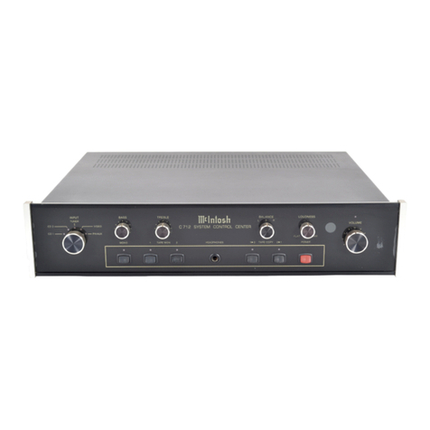
TheMcIntoshAudioCompensatorisa completecontrolunitforprofessional
orhomeentertainmentsystems.TheModelC-8derivesitspowerfromany
McIntoshpoweramplifier:theModelC-8Pisself-powered.
Fiveinputchannelsareprovided:threewhichproduceconstantamplifica-
tionovertheaudiospectrumof20-20,000cycles,andtwowhichareequalizedfor
magneticphonographcartridges.
THEAUDIOCOMPENSATORISA COMPLETEPRE-AMPLIFIERAND
RECORDCOMPENSATOR:THEREFORE,THEUSEOFANAUXILIARYEQUAL-
IZERORPRE-AMPLIFIERWITHTHISUNITISNOTRECOMMENDED.
INSTALLATIONOFMODELC-8andC-8P,
AUDIOCOMPENSATORS
TheC-8andC-8PAudioCompensatormaybemountedinanytypeequip-
mentcabinet,relayrackpanel,door,wall,etc.,orinitsowncabinetforchair
sideoperation.ItisnotnecessarytodisassembletheAudioCompensatorfor
mounting.Cuta rectangularholeinthepaneltobeusedformounting,insertthe
AudioCompensator,andsecurewithwoodormachinescrews.Mountingtem-
platesareprovidedwiththismanualfortheC-8andC-8P.
WheninstallingtheC-8P,thepowersupplysectionshouldbemountedat
leasttwofeetfromtheAudioCompensator.
Aftertheseunitshavebeensecuredintheirdesiredlocation,proceedas
follows:
1.Connectspeakertooutputofpoweramplifier.
2.InsertpoweramplifierlinecordintooneoftheAuxiliaryA.C.
receptaclesprovidedattherearchassisoftheAudioCompensator.

-2 -
3.C-8:Connectinter-unitcabletosocketlabeled"PRE-AMP.
INPUT"onMcIntoshpoweramplifiers.
CAUTION:THEINTER-UNITCABLEMUSTNOTBEREMOVED
FROMTHEC-8.
C-8P:InsertcableofD-8powersupplyintosocketlabeled"INTER-
UNITCABLE"onC-8P.Connectaudiocableprovidedbetween
RETMApinjacklabeled"MAINOUTPUT"onC-8Pand2.5Vinput
ofpoweramplifier.(Socketlabeled"PRE-AMPINPUT"onMcIntosh
poweramplifiers.)
4.TheAudioCompensatordelivers2.5voltsofaudiosignalatfull
output.Thegaincontrolofthepoweramplifiershouldbe
adjustedasoutlinedintheamplifierinstructionmanualforthis
sensitivity.
5.TurnthevolumecontrolontheAudioCompensatorto"OFF".
6.InsertpowercordoftheAudioCompensatorintoa 117V.A.C.
poweroutlet.
7.TurntheSelectorswitchontheAudioCompensatorto"5"and
Basscontrolfullyclockwise.
8.TurnthevolumecontrolontheAudioCompensatorclockwise
untilthepowerswitchisactivated.Allowthirtysecondsfor
warm-up,thenadvancethevolumecontrolto"10".
9.C-8:Adjustthehumreducingpotentiometeronthepower
amplifierforminimumhum.
C-8P:Adjustthehumreducingpotentiometeronthepower
supplyforminimumhum.
10.TurnthevolumecontrolontheAudioCompensatortooff.
11.InsertinputsintotheirproperjacksatthebackoftheAudio
Compensator,andallA.C.powercordsintotheA.C.outlets
provided.

-3-
INPUTCONNECTINGPROCEDURE
TheinherenthumandnoisevoltagesappliedtotheinputoftheAudio
Compensatorare-110DBM,orlessthan3 microvolts.Toavoidloweringthesig-
naltohumratiooftheAudioCompensator,byaddinghumvoltagestotheinput,
extremecaremustbetakeninitsinstallation.Weofferthefollowingrecommenda-
tionsasa guidetoinstallation:
1.ConnectinputsofAudioCompensatorasoutlinedonthetablebelow.
CHANNEL
1& 2
3
4
5
FORUSEWITH
AM-FMTuners
WireReproducers
TapeReproducers
CrystalorCeramic
cartridges
CrystalMicrophones
LowImpedance
Microphone
HighlevelMagnetic
cartridges.(Termi-
natedforPickering
cartridge)
Lowlevelmagnetic
cartridgesorampli-
tuderesponsive
cartridgessuchas
FMorceramic
INPUT
(FOR2.5V.OUTPUT)
MIN.MAX.
70MV.20V.
10MV.1 V.
30MV.150MV.
10MV.50MV.
GAIN
32db
50db
40db
50db
REMARKS
Inputlevelsinexcess
of.07Vshouldbere-
ducedbypotentiometers
onbackpanel.
Inputlevelsinexcess
of10MVshouldbe
reducedbypotentiom-
eteronbackpanel.
Seetextforoperation
ofthesechannels.
TheAudioCompensatorandmagneticphonographcartridgesshould
bemountedatleasttwofeetfrompowertransformers.
Inter-unitcablesprovidea completegroundsystem.Alternate
groundwirescreategroundloopswhichwillusuallyincreasehum
level.

-4 -
4.Theheatersofthe12AX7tubesusedintheC-8arereturnedto
groundthrougha humreducingpotentiometerinthepower
amplifier.HeatersoftubesusedintheC-8Parereturnedto
groundthrougha humreducingpotentiometerinthepower
supply.Thiscontrolrequiresaninitialadjustmentformini-
mumhum,andshouldbereadjustedeachtimeoneormore
tubesarereplaced.
5.GroundingtheturntablemotorframetotheAudioCompensator
chassisneartheinputjacksmayreducethehumlevelonthe
phonographchannels.
OUTPUTCONNECTIONS
Threeoutputsareprovided:oneauxiliaryandtwomainoutputs.
Theauxiliaryoutputmaybeusedforrecordingtapefromanysourcecon-
nectedtotheAudioCompensator.TheSelectorswitch,BassandTreble
compensationswitches,andRumbleFilterareeffectiveatthisoutput.Adjust-
mentoftheBassandTrebletonecontrols,AuralCompensatorandVolume
controlmaybemadeformonitoringpurposeandwillnotaffecttherecorded
signal.Theauxiliaryoutputdeliversa signalofonevolt.
Allcontrolsareeffectiveatthemainoutputs,whichareavailableatthe
octalsocketlabeled"INTER-UNITCABLE"betweenpins#1and#2(pin#1is
ground),andattheRETMApinjacklabeled"MAINOUTPUT".Theinter-unit
cableconnectingtheC-8toanyMcIntoshpoweramplifierusestheoctalsocket
output.Thepinjackoutputmaybeusedfordrivinga secondpoweramplifier
ifsodesired.
Themainandauxiliaryoutputjacksarefedfromcathodefollowers.The
inputimpedanceofdevicesconnectedtotheseoutputsshouldbe50,000ohms
orgreater,andthecapacitivereactanceofaudiocablesconnectingthese
devicesshouldnotbelessthan8,000ohmsat20,000cycles.Thisisthe
reactanceofa capacityof1000mmf.Audiocablehavinga capacityof25mmf
perfootmaybe40feetlong.

-5 -
TYPICALINSTALLATION
AUDIOCOMPENSATOR,C-8
TYPICALINSTALLATION
AUDIOCOMPENSATOR,C-8P
(SELFPOWERED)

COMPENSATEFOREAR
CHARACTERISTICAT
REDUCEDVOLUMEON
ALLCHANNELS.
SELECTDESIREDTREBLE
ROLL-OFFONALLCHANNELS.
SELECTDESIREDBASS
COMPENSATIONON
CHANNELS4 AND5.
REDUCETURNTABLERUMBLE,
ORLOWFREQUENCYDISTURB-
ANGESONALLCHANNELS.
-6 -
SELECTANYONEOFFIVE
INPUTCHANNELS.UNUSED
CHANNELSAREGROUNDED
TOPREVENTCROSSTALK.CONTROLBASSRESPONSE
ONALLCHANNELSCONTROLTREBLERESPONSE
ONALLCHANNELS.
CONTROLVOLUMEON
ALLCHANNELS,ON-OFF
CONTROL.
Channels1 and2:
Channels1 and2 areeachterminatedbya potentiometermountedontheback
panelwhichshouldbeusedtoreducesignalinputtothesechannelsifinexcessof
.07volts.Correctadjustmentoccurswhenthesoundlevelofchannels1 and2 is
equivalenttothatofchannels4 or5.Highimpedancesources,suchascrystal
microphonesandthedetectoroutputoftuners,maybeconnecteddirectlytothese
channelssincetheyhaveaninputimpedanceof660,000ohms.
Channel3:
Channel3 isterminatedbya 100,000ohmpotentiometermountedontheback
panelwhichshouldbeusedtoreducesignalinputtothischannelifinexcessof
10MV.Lowimpedancemicrophonesinconjunctionwithaninputtransformer,
suchasMcIntoshM-107,maybeusedonthischannel.
Channels1,2 and3 provideflatamplificationfrom20to20,000cycles.All

-7 -
frontpanelcontrolsareeffective,withtheexceptionoftheBassCompensation
switches,andmaybeusedtoaltertheresponseasdesired.
Channel4:
Channel4 is equalizedforusewithhighlevelmagneticcartridgesdelivering
30MVofsignal.ItisterminatedforusewiththePickeringcartridge.
Channel4 maybemodifiedforusewithotherhighlevelmagneticcartridgesby
changingtheterminatingpadofR6andR7,ormaybeusedfora secondlowlevel
cartridgebyreplacingR6andR7witha singleterminatingresistorasrecommended
bythecartridgemanufacturer.
Channel5:
Channel5 isequalizedforusewithlowlevelmagneticcartridgessuchas
G.E.,Audax,orFairchildwithinputtransformer.A variableterminatingcon-
trolisprovided,anda switchforselectingeithermagneticcartridges(velocity
responsive),oramplituderesponsivecartridges,suchasa ceramicorF.M.type.
Whenusinga magneticcartridgethisswitchshouldbeinthe"MAG"position
andthecontrollabeled"LOAD"shouldbeadjustedtotheresistancerecommended
bythemanufacturer.Highfrequencyroll-offofthecartridgemaybeobtainedby
decreasingtherecommendedload. Theloadcontroliscalibratedfrom"0"to
"100"witheachcalibrationrepresentingthousandsofohms.
Amplituderesponsivecartridgesmaybeusedonchannel5 toallowfulluse
oftheextremelyflexiblecompensationavailable.Byplacingtheslideswitchin
position"F.M."andthe"LOAD"controlto"100",cartridgesofthistypemaybe
used.
Allcontrolsareeffectiveonchannels4 and5.
TheBassandTreblecompensationswitchesmaybeusedtocompensate
recordingsasrecommendedbythemanufacturerortoadjustthecompensationfora
morepleasingtonalbalanceforthelistener.TheBassandTrebletonecontrols
areindependentofthecompensationswitchesandmaybeusedasfineadjustments
inconjunctionwiththeseswitches.Inaddition,a rumblefilterisprovidedto
reduceturntable"wow"and"rumble".
•
ThefivepositionchannelSelectorswitchmaybeusedtoselectanyofthe
fiveinputchannelsavailable.
TheVolumecontrolselectsthedesiredlisteninglevelandsinceitislocated
attheoutputoftheAudioCompensator,thehighsignaltonoiseratiooftheunitis
maintainedatalllevels.Byproperlyadjustingtheinputpotentiometeronchannels

-8 -
1,2 and3 thevolumelevelcanbeheldequalforallchannels;thesignalwill
remainata constantloudnesswhenswitchingfromonechanneltoanother.The
masteroff-onswitchisattachedtothevolumecontrol.Thisswitchcontrolsthe
threeauxiliaryA.C.outletsontherearpaneloftheAudioCompensatoraswellas
thethreeauxiliaryA.C.outletsonthepowersupplyoftheC-8P.
Theauralcompensatormaybeusedtocompensatefortheresponsecharac-
teristicoftheearatreducedvolume.Thiscontroldecreasesthemid-range
frequencieswhileleavingthelowandhighfrequenciesatrelativelyconstant
intensity.Byreducingvolumelevelwiththiscontrolproperbalanceofthepro-
grammaterialcanbemaintained.
GUARANTEE
Weguaranteetheperformanceofthisequipmentandthemechanicalandelec-
tricalworkmanshiptobefreeofseriousdefectsfora periodof90days.This
guaranteedoesnotextendtocomponentsdamagedbyimproperusenordoesit
extendtotransportationtoandfromthefactory.
McINTOSHLABORATORYINC.
320WaterStreet
Binghamton,N.Y.,U.S.A.
ELECTRICALANDMECHANICALSPECIFICATIONS
PowerSourceC-8:AnyMcIntoshPowerAmplifier
C-8P:Self-powered
OutputMain:2.5 volts
Auxiliary:1 volt
InputlevelChannels1 & 2:70MV-20volts
Channel3:10MV
Channel4:30MV(MagneticCartridge)
Channel5:10MV(Magneticorconstant
amplitudecartridge)
FrequencyResponseSeeGraphs
HarmonicDistortionLessthan. 3%at2.5 voltsoutput,20-20,000cycles
HumandNoise-110db(2.5 microvolts)orlower,(referredtoinput)
0db=.775volts
SizeC-8:10"x 3-1/2"x 7-1/211
FrontPanel11"x 4-1/4"
C-8P:Same
D-8(PowersupplysectionofC-8P):5-l/2"x4-3/4"x2-3/8"
WeightC-8:6 lbs.
C-8P:8 lbs.

-
9
-

-10-
VOLTAGEANDRESISTANCECHART
Resistancesmeasuredtogroundwithpin#4ofinter-unitcablesocketshortedtopin#1
D.C.VoltagesmeasuredwithVTVMtogroundusingD-8powersupply.
Signalvoltagemeasuredwithallcontrolsinflatposition,1000cyclesignalof
10MVinchannel3,volumecontrolfullyon,andwitha VTVM.
Tube
Input
Tube
Center
Tube
Output
Tube
PinNo.
1
2
3
4& 5
6
7
8
9
1
2
3
4& 5
6
7
8
9
1
2
3
4& 5
6
7
8
9
Resistance
430K
1M
4.1K
*0-65ohms
440K
1M
1.8K
*0-65ohms
110K
440K
330K
*0-65ohms
110K
200K
102K
*0-65ohms
340K
**0-lmeg
1.8K
*0-65ohms
12K
1.1M
102K
*0-65ohms
D.C.Voltage
110V
0
1.2V
*0-4.8V.A.C.
108V
0
1.2V
*0-6.3V.A.C.
195V
108V
110V
*0-4.8V.A.C.
195V
45V
55V
#0-6.3V.A.C.
160V
0
1.2V
*0-4.8V.A.C.
95V
25V
350V
*0-6.3V.A.C.
SignalVoltage
17MV
10MV
9.5MV
--
1.25V
17MV
0--
0
1.25V
1.2V
__
0
1.0V
1.1V
--
2.7V
95MV
14MV
--
0
2.65
2.85
--
*Dependsonpositionofhumreducingpotentiometer.
**DependsonpositionofBasspotentiometer.100K,Bassat"0"

C-l1.345
MCINTOSHLABORATORY,INC.
320WaterStreet,Binghamton ,NewYork
MODELC-8P,AUDIOCOMPENSATO R
7-7-54
-11-
Other manuals for C8 - SCHEMATICS
4
This manual suits for next models
1
Table of contents
Other McIntosh Control Unit manuals
Popular Control Unit manuals by other brands

ZURN
ZURN WILKINS 950LF Installation, Testing, Maintenance Instructions

Acromag
Acromag BusWorks 900MB Series user manual

Lutron Electronics
Lutron Electronics LQR-WPM-6D Installation and operation guide

Reverso
Reverso FPS-80 instructions

ELBRO
ELBRO Butler SMSB131BW instruction manual

Madas
Madas M16/RMO NA/NC installation instructions