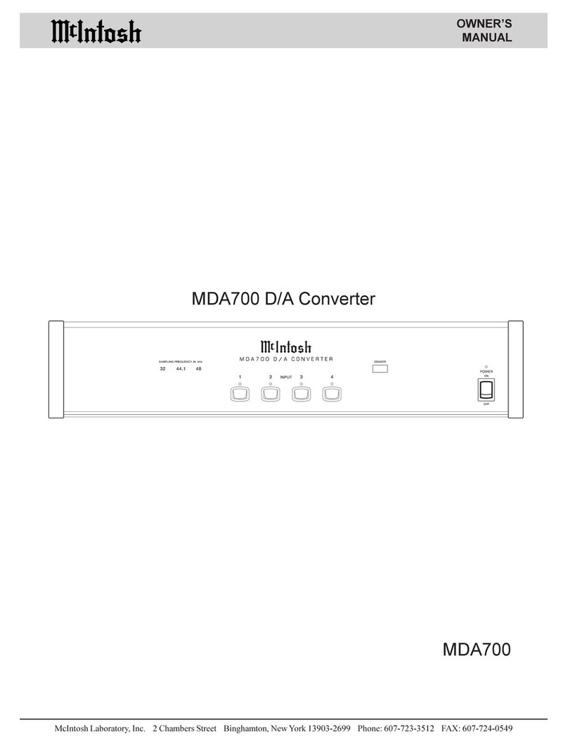
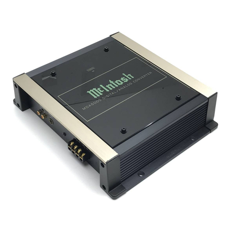
McIntosh MDA1000 User manual

MDA1000
Owner’s Manual
McIntosh Laboratory, Inc. 2 Chambers Street Binghamton, New York 13903-2699 Phone: 607-723-3512 FAX: 607-724-0549
D/A Converter

2
IMPORTANT SAFETY
INSTRUCTIONS!
PLEASE READ THEM BEFORE
OPERATING THIS EQUIPMENT.
WARNING - TO REDUCE RISK OF
FIRE OR ELECTRICAL SHOCK, DO
NOT EXPOSE THIS EQUIPMENT TO
RAIN OR MOISTURE.
The lightning flash with arrowhead, within
an equilateral triangle, is intended to alert
the user to the presence of uninsulated
“dangerous voltage” within the product’s
enclosure that may be of sufficient mag-
nitude to constitute a risk of electric
shock to persons.
NO USER-SERVICEABLE PARTS
INSIDE. REFER SERVICING TO
QUALIFIED PERSONNEL.
To prevent the risk of electric shock, do not remove cover or
back. No user serviceable parts inside.
The exclamation point within an equi-
lateral triangle is intended to alert the
user to the presence of important op-
erating and maintenance (servicing)
instructions in the literature accompa-
nying the appliance.
1. Read these instructions.
2. Keep these instructions.
3. Heed all warnings.
4. Follow all instructions.
5. Do not use this apparatus near water.
6. Clean only with a dry cloth.
7. Do not block any ventilation openings. Install in
accordance with the manufacturer’s instructions.
8. Do not install near any heat sources such as
radiators, heat registers, stoves, or other
apparatus (including amplifiers) that produce heat.
9. Do not defeat the safety purpose of the polarized
or grounding-type plug. A polarized plug has two
blades with one wider than the other. A grounding
type plug has two blades and a third grounding
prong. The wide blade or the third prong are
provided for your safety. If the provided plug
does not fit into your outlet, consult an electrician
for replacement of the obsolete outlet.
10. Protect the power cord from being walked on or
pinched particularly at plugs, convenience
receptacles, and the point where they exit from
the apparatus.
11. Only use attachments/accessories specified by the
manufacturer.
12. Use only with the cart, stand, tripod, bracket, or
table specified by the manufacturer, or
sold with the apparatus. When a cart
is used, use caution when moving the
cart/apparatus combination to avoid
injury from tip-over.
13. Unplug this apparatus during lightning storms or
when unused for long periods of time.
14. Refer all servicing to qualified service personnel.
Servicing is required when the apparatus has been
damaged in any way, such as power-supply cord
or plug is damaged, liquid has been spilled or
objects have fallen into the apparatus, the
apparatus has been exposed to rain or moisture,
does not operate normally, or has been dropped.
15. Do not expose this equipment to dripping or
splashing and ensure that no objects filled with
liquids, such as vases, are placed on the
equipment.
16. To completely disconnect this equipment from the
a.c. mains, disconnect the power supply cord
plug from the a.c. receptacle.
17. The mains plug of the power supply cord shall
remain readily operable.
3
Customer Service
Technical Assistance
Please Take A Moment
Thank You
Copyright 2003, 2007 ©by McIntosh Laboratory, Inc.
The serial number, purchase date and McIntosh Dealer
name are important to you for possible insurance claim or
future service. The spaces below have been provided for
you to record that information:
Your decision to own this McIntosh MDA1000 D/A Con-
verter ranks you at the very top among discriminating music
listeners. You now have “The Best.” The McIntosh dedica-
tion to “Quality,” is assurance that you will receive many
years of musical enjoyment from this unit.
Please take a short time to read the information in this
manual. We want you to be as familiar as possible with all
the features and functions of your new McIntosh.
Serial Number:
Purchase Date:
Dealer Name:
If it is determined that your McIntosh product is in need of
repair, you can return it to your Dealer. You can also return
it to the McIntosh Laboratory Service Department. For as-
sistance on factory repair return procedure, contact the
McIntosh Service Department at:
McIntosh Laboratory, Inc.
2 Chambers Street
Binghamton, New York 13903
Phone: 607-723-3515
Fax: 607-723-1917
If at any time you have questions about your McIntosh
product, contact your McIntosh Dealer who is familiar with
your McIntosh equipment and any other brands that may be
part of your system. If you or your Dealer wish additional
help concerning a suspected problem, you can receive tech-
nical assistance for all McIntosh products at:
McIntosh Laboratory, Inc.
2 Chambers Street
Binghamton, New York 13903
Phone: 607-723-1545
Fax: 607-723-3636
Table of Contents
Safety Instructions ............................................................ 2
Thank You and Please Take a Moment ............................. 3
Technical Assistance and Customer Service ..................... 3
Table of Contents .............................................................. 3
Important Information ....................................................... 4
Connector Information ...................................................... 4
Introduction ....................................................................... 5
Performance Features ....................................................... 5
Dimensions ........................................................................ 6
Installation ........................................................................ 7
Rear Panel Connections ..................................................... 8
How to Connect for Power Control and Data .................... 9
How to Connect for Audio ............................................... 10
Front Panel Controls, Displays, Push-buttons,
and Switch ....................................................................... 11
How to Operate the Setup Mode ...................................... 12
Default Settings and Bypass Mode .................................. 12
Display Brightness and Re-Title Inputs ........................... 13
Remote Control Push-buttons .......................................... 14
How to Operate the Remote Control ................................ 15
How to Operate the MDA1000 ........................................ 16
Specifications ................................................................... 18
Packing Instructions ......................................................... 19

4
XLR Connectors:
Below is the Pin configuration for the XLR Balanced Ana-
log Audio Output Connectors on the MDA1000. Refer to
the diagram for connection:
PIN 1: Shield/Ground
PIN 2: + Signal
PIN 3: - Signal
Below is the Pin configuration for the XLR Balanced Digi-
tal Audio Input Connectors on the MDA1000. Refer to the
diagram for connection:
PIN 1: Shield/Ground
PIN 2: + Signal
PIN 3: - Signal
Power Control and Trigger Connectors
The MDA1000’s Power Control Outputs provide a 5 volt
signal. Use a 1/8 inch stereo mini phone
plug to connect to the Power Control In-
put on other McIntosh Components.
Data and IR Port Connectors
The MDA1000’s Data Port Output provides Remote Con-
trol Signals and the IR
Input Port allows for the
connection of other
brands IR Sensors. Use a
1/8 inch stereo mini
phone plug to connect to
the Data Port Inputs on
McIntosh Source Units.
Connector InformationImportant Information
1. It is recommended that a qualified professional assist you in
the choice and installation of a McIntosh Audio System for
your home.
2. Before making any connections to the MDA1000, make sure
that the Main POWER Switch is in the Off position. When
the MDA1000 and other McIntosh Components are in their
Standby Mode the Microprocessor’s Circuitry inside each
component is active and communication is occurring
between them. Failure to do so could result in
malfunctioning of some or all of the system’s normal
operations.
3. The following Connecting Cable is available from the
McIntosh Parts Department:
Data and Power Control Cable Part No. 170-202
Six foot, 2 conductor shielded, with two 1/8 inch stereo
mini phone plugs.
4. When the MDA1000 Digital XLR Input is used to connect
with the Digital XLR Output of the McIntosh MCD1000 CD
Transport Component, it is important to use a twisted pair
shielded cable.
5. For additional connection information, refer to the owner’s
manual(s) for any component(s) connected to the
MDA1000.
6. With the LEVEL Control active, the MDA1000 is capable of
driving a power amplifier directly. When the MDA1000 is
connected to a Preamplifier Input and the LEVEL Control
is active, LEVEL Control settings above 81 (as indicated on
the Front Panel Alphanumeric Display) may cause some
Preamplifier Inputs to overload due to the high signal level.
Positive
N/C
Ground
IR Input Port Connector
Data Signal
Ground
N/C
Data Signal
N/C
Data Ground
Data Port Connector
Pin 1
Pin 2
Pin 3
Pin 1
Pin 2
Pin 3

5
••
••
•Shielded 768kHz Up Sampling Module
The McIntosh designed Up Sampling Module converts all
of the incoming Digital Signals to the higher frequency of
768kHz with 24Bit resolution before the Digital to Analog
process begins.
••
••
•Shielded 24 Bit Digital to Analog Circuits
The MDA1000 utilizes McIntosh’s own specially designed
24-bit Balanced Parallel Digital to Analog Converter Circu-
itry operating at 768kHz. This offers the widest possible
dynamic range, lowest noise level and extremely low distor-
tion. All of this produces sound quality that is truly excep-
tional.
••
••
•Special Analog Filter and Output Amplifier
The third order Butterworth gentle slope analog filter re-
moves any remaining digital artifacts from the output sig-
nal. The low impedance Output Amplifer drives both the
Balanced and Unbalanced Output Connections.
••
••
•Balanced and Unbalanced Outputs
Balanced connections guard against induced noise and al-
low long cable runs without compromising sound quality.
There are also Unbalanced connections for components
without Balanced Inputs.
••
••
•Precision Tracking Volume Control
Volume levels are controlled by a Precision Digitally Con-
trolled Attenuator System with a tracking accuracy of
0.1dB. There is also a Volume Control Bypass Mode for a
fixed output level.
••
••
•Alphanumeric Fluorescent Display
The Multifunction Front Panel Display indicates the Source
Selection, Volume Levels and the Setup Mode Selections.
The displays intensity is fully adjustable.
••
••
•Digital Inputs with Title Reassignment
The MDA1000 has provisions for three Coaxial Digital In-
Introduction
Performance Features
puts, three Optical Digital Inputs and one XRL Balanced
Digital Input. Any of the seven inputs can have their Input
Title reassigned to match the sources connected to the
MDA1000.
••
••
•Precision Parts
Only the finest precision 1% tolerance metal film resistors
and 5% tolerance Polyfilm Fliter Capacitors are used
throughout.
••
••
•Low Distortion
Distortion levels of all types are less than 0.002%. Music is
amplified with total transparency and accuracy.
••
••
•Remote Power, Data Control and External IR Input
Remote Power Control In/Out allows the MDA1000 to turn
On/Off with a McIntosh Audio Control Center. The Data
Port Input allows Remote Control Operation from another
McIntosh Component. The IR Input allows for the connec-
tion of an IR Receiver.
••
••
•Remote Control Operation
A Remote Control is included that allows for complete con-
trol of major functions.
••
••
•Glass Front Panel
The famous McIntosh Illuminated Glass Front Panel with a
three dimensional look ensures the pristine beauty of the
MDA1000 will be retained for many years.
••
••
•Fiber Optic Solid State Front Panel Illumination
The Illumination of the Front Panel is accomplished by the
combination of custom designed Fiber Optic Light Diffusers
and Light Emitting Diodes (LEDs). This provides even
Front Panel Illumination, together with the extra long life
LEDs.
••
••
•Machined Top and Side Panels
The Top and Side of the MDA1000 are machined from
thick aluminum panels with a smooth black anodized finish.
In the recessed area of the Top Panel is a screened glass
panel with a block diagram of the MDA1000’s circuitry.
••
••
•Special Power Supply
A fully regulated Power Supply with a special R-Core
Power Transformer, ensures stable noise free operation even
though the power line varies.
Introduction and Performance Features
The new McIntosh MDA1000 D/A Converter offers a
highly refined Balanced/Parallel Circuit utilizing eight of
Burr Brown’s most sophisticated 24 Bit Digital to Analog
(D/A) chips. Combine a MDA1000 with a McIntosh
MCD1000 CD Transport and you will enjoy a playback
system of unparalleled performance.

6
Dimensions
The following dimensions can assist in determining the best
location for your MDA1000. There is additional informa-
tion on the next page pertaining to installing the MDA1000
into cabinets.
Dimensions
17-1/2"
44.45cm
4-5/8"
11.75cm
6"
15.24cm
12-1/8"
30.79cm
15-7/8"
40.32cm
3/16"
0.48cm 4-13/16"
12.22cm
9"
22.86cm
1-7/16"
3.65cm
13-1/4"
33.65cm
17"
43.18cm
1/4"
0.64cm
Front View
of the
MDA1000
5-5/16"
13.49cm
15/16"
2.38cm
Rear View
of the
MDA1000
Side View
of the
MDA1000

7
Installation
The MDA1000 can be placed upright on a table or shelf
standing on its four feet. It also can be custom installed in a
piece of furniture or cabinet of your choice. The four feet
may be removed from the bottom of the MDA1000 when it
is custom installed as outlined below. The four feet together
with the mounting screws should be retained for possible
future use if the MDA1000 is removed from the custom in-
stallation and used free standing. The required panel cutout,
ventilation
cutout and
unit dimen-
sions are
shown.
Always
provide ad-
equate ventila-
tion for your
MDA1000.
Cool opera-
tion ensures
the longest
possible oper-
ating life for
any electronic
instrument.
Do not install
the MDA1000
directly above
a heat generat-
ing component
such as a high
powered am-
plifier. If all
the compo-
nents are in-
stalled in a
single cabinet,
a quiet run-
ning ventila-
tion fan can be
a definite asset
in maintaining
all the system
components at
the coolest
possible oper-
ating tempera-
ture.
A custom
cabinet instal-
Installation
4-7/8"
12.38cm
17-1/16"
43.34cm
Cutout Opening for Custom Mounting
MDA1000 Front Panel
Custom Cabinet Cutout
4"
10.16cm
12"
30.48cm 13-1/4"
33.66cm
1"
2.54cm
Cutout
Opening
for
Ventilation
Cutout Opening
for Ventilation
Support
Shelf
Cabinet
Front
Panel
Chassis
Spacers
MDA1000 Side View
in Custom Cabinet
MDA1000 Bottom View
in Custom Cabinet
3-3/32"
7.86cm
6-7/32"
15.79cm
7"
17.78cm
lation should provide the following minimum spacing di-
mensions for cool operation. Allow at least 2 inches
(5.08cm) above the top, 2 inches (5.08cm) below the bottom
and 1 inch (2.54cm) on each side of the D/A Converter, so
that airflow is not obstructed. Allow 17 inches (43.18cm)
depth behind the front panel. Allow 1-1/8 inch (2.9cm) in
front of the mounting panel for knob clearance. Be sure to
cut out a ventilation hole in the mounting shelf according to
the dimensions in the drawing.

8
Rear Panel Connections
IR INPUT for
connecting an
IR Receiver
POWER CONTROL IN
receives turn-On signals
from a McIntosh Compo-
nent and POWER CON-
TROL OUT sends turn-On
signals on to another McIn-
tosh Component
DATA IN receives
operating data from
a McIntosh Control
Center
COAXIAL DIGITAL
AUDIO INPUTS re-
ceive digital audio
signals from source
components
Connect the MDA1000
power cord to a live
AC outlet. Refer to in-
formation on the back
panel to determine the
correct voltage
BALANCED AUDIO OUTPUTS
contain analog stereo signals to
connect to Balanced inputs of
other components
UNBALANCED AUDIO OUTPUTs
contain analog stereo signals to con-
nect to Unbalanced inputs of other
components
OPTICAL DIGITAL
AUDIO INPUTS re-
ceive digital audio sig-
nals from source com-
ponents
DATA PORTs send signals
to compatible source compo-
nents to allow remote con-
trol operation
Balanced DIGITAL
AUDIO INPUT re-
ceives digital audio
signals from the
McIntosh MCD1000
CD Transport

9
McIntosh CD Player
How to Connect for Power Control and Data
The Power Control Connections facilitate the ability to
switch power On and Off to the McIntosh Source Compo-
nents automatically with the McIntosh Control Center/
Preamplifier. Data Control Connections facilitate the ability
to remotely operate McIntosh Source Components using the
supplied MDA1000 D/A Converter Remote Control or the
McIntosh Control Center/Preamplifier Remote Control.
1. Connect a Power Control Cable from the MDA1000
POWER CONTROL IN Jack to the appropriate Power
Control Out Jack on the McIntosh Control Center/
Preamplifier.
Note: If the MDA1000 is connected to a McIntosh
MCD1000 CD Transport in a system without a
McIntosh Control Center or Preamplifier, the
MDA1000’s Power Control In should be connected
to the MCD1000 Power Control Out Jack.
2. Connect a Power Control Cable from the MDA1000
POWER CONTROL OUT Jack to the McIntosh
MCD1000 CD Transport Power Control In Jack.
3. Optionally, connect a Power Control Cable from the
MCD1000 Power Control Out Jack to the McIntosh
CD Player Power Control In Jack.
4. Connect a Data Control Cable from the MDA1000
DATA IN Jack to the LINE 1 Data Port on the McIn-
tosh Control Center/Preamplifier.
5. Connect a Data Control Cable from the MDA1000
DATA SWITCHED DATA OUTPUTS Jack 1 to the
McIntosh MCD1000 CD Transport Data In Jack.
6. Connect a Data Control Cable from the MDA1000
DATA SWITCHED DATA OUTPUTS Jack 4 to the
McIntosh CD Player Data In Jack.
McIntosh MCD1000 CD Transport
McIntosh Controller

10
McIntosh Preamplifier
1. Connect Audio Cables from the McIntosh MDA1000
Left and Right BALANCED AUDIO OUTPUTS to the
McIntosh Audio Control Center/Preamplifier Line 1
Balanced Inputs.
Note: The MDA1000’s UNBALANCED Left and Right
AUDIO OUTPUTS may be used instead of the
BALANCED Connections. The UNBALANCED and
BALANCED AUDIO OUTPUTS may both be used
at the same time.
2. Connect a Coxial Digital Cable from the McIntosh
MCD1000 CD Transport Coxial Digital Audio Output
to the MDA1000 COXIAL 1 DIGITAL AUDIO IN-
PUT.
How to Connect for Audio
Note: A Balanced Digital XLR Cable with internal
wiring consisting of a Shielded Twisted Pair may
be used in place of the Coxial Digital Cable. The
Cable would connect from the MCD1000 CD
Transport XLR Output to the MDA1000 XRL
DIGITAL AUDIO INPUT number 7.
3. Connect an Optical Digital Cable from the McIntosh
CD Player Optical Digital Audio Output to the
MDA1000 OPTICAL 4 DIGITAL AUDIO INPUT.
4. Connect the MDA1000 Power Cord to a live AC outlet.
McIntosh CD Player
McIntosh MCD1000 CD Transport
To AC
Outlet

11
Front Panel Controls, Displays, Push-Buttons, and Switch
Main Switch turns
all AC power com-
pletely On or Off
Selects various Digital
Sources for listening
This Push-button with indicator, activates
the Setup Mode. Setup allows the chang-
ing of the Input Titles, Volume Setting
and the Display Bightness from the de-
fault settings.
Adjusts the listening
volume level and also
selects various setup
functions
IR Sensor for
Remote Con-
trol Operation
Switches the MDA1000
On or Off (Standby). The
LED Indicator illumi-
nates when there is in-
coming AC Power
Indicates the Sources,
Volume Levels, Opera-
tional Functions and
Setup Mode Settings

12
Bypass Mode
The MDA1000 Audio Outputs can be set for either a fixed
output level or a variable output that is controlled by the
Front Panel LEVEL Control. To change from the default
setting of a fixed output level to a variable output level per-
form the following:
1. Press the SETUP Push-button once to access the BY-
PASS MODE in Setup. Refer to figures 3 and 4.
2. Rotate the LEVEL Control Counterclockwise until the
Front Panel Alphanumeric Display indicates BYPASS
OFF. Refer to figure 5.
3. Press the SETUP Push-button three times to exit the
Setup Mode. The LED above the SETUP Push-button
will be extinguished.
How to Operate the Setup Mode
Your McIntosh MDA1000 has been factory configured for
default operating settings that will allow immediate enjoy-
ment of superb audio without the need for further adjust-
ments. If you wish to make changes to the factory default
settings, a Setup Feature is provided to customize the oper-
ating settings using the Front Panel Alphanumeric Display.
1. Press the POWER Switch to ON, the LED above the
STANDBY/ON Push-button will illuminate and the
Front Panel Display will indicate “BYPASS ON” for
several seconds and then “1 COAXIAL 44.1”. Refer to
figures 1, 2 and 3.
Notes: For normal operation, switch the MDA1000 On and
Off with the Standby/On Push-button. If the
MDA1000 is not going to be used for an extended
period of time, turn Off all AC Power with the Power
Switch. If there is no digital signal present at the
Coaxial Digital Input 1, the Front Panel
Alphanumeric Display will indicate “1 COAXIAL”
and not “1 COAXIAL 44.1” as illustrated in figure 2.
2. Press the SETUP Push-button and notice that with each
press of the push-button, the Setup Mode advances
through two different possible adjustment selections and
one informational display.
3. To exit from the Setup Mode, press the SETUP Push-
button until the LED above the SETUP Push-button is
extinguished and the Front Panel Display reverts back
to its normal display. Refer to figure 2.
The following listings indicate the default settings and the
page number for instructions on how to change a setting:
Setup Function Name Setting Page Number
Bypass ON 12
Display MAX 13
Input Title 1 COAXIAL 13
Default Settings
Figure 1
Figure 2 Figure 4
Figure 5
Figure 3

13
Display Brightness
The Front Panel Alphanumeric DISPLAY Brightness may
be varied from the default setting of MAXIMUM (Bright)
to MINIMUM (Dim). Follow the steps below for reducing
the Display Brightness. Refer to figures 3 and 6.
1. Press the SETUP Push-button two times to access the
DISPLAY Mode in Setup.
2. Rotate the LEVEL Control Counterclockwise until the
Front Panel Alphanumeric Display Brightness is re-
duced to the desired setting. Refer to figure 7.
3. Press the SETUP Push-button two times to exit the
Setup Mode. The LED above the SETUP Push-button
will be extinguished.
Setup
Figure 6
Figure 7
Re-Title Inputs
The MDA1000 has seven Digital Audio Inputs with as-
signed titles that will allow for immediate connection, op-
eration and enjoyment. These inputs may be renamed to
match the digital components in your system. The following
example will illustrate how to rename the 1 COAXIAL In-
put to 1 CD1. When the Input Selector is rotated to select
what was originally the 1 COAXIAL Input, 1 CD1 will
now appear on the Front Panel Alphanumeric Display.
Note: The New Input Titles that are available for all the
Inputs include CD1, CD2, CD3, DVD1, DVD2,
DVD3, LD, VCR, SAT, AUX1 and AUX2.
1. Press the SETUP Push-button three times to access the
Re-Title Mode in Setup. Refer to figures 3.
2. Rotate the INPUT Control Clockwise to select the de-
sired Digital Audio Input to be Re-Titled. Refer to fig-
ure 8.
3. Rotate the LEVEL Control Clockwise until the Front
Panel Alphanumeric Display indicates the desired input
name. Refer to figure 9.
Figure 8
Figure 9
4. To Re-Title additional input(s) repeat steps 2 and 3.
5. Press the SETUP Push-button to exit the Setup Mode.
The LED above the SETUP Push-button will be extin-
guished.

14
Remote Control Push-Buttons
Move forward one Track at a time
Press to Stop Disc
Playback at any time
Starts Standard Disc Playback and
Program Playback
Press a Number Push-button to select
the desired Track
Press the Input push-button fol-
lowed by pressing one of the
Numbered Push-Buttons to se-
lect the desired Digital Input of
the MDA1000
Press the Up (+) or Down (-)
Push-buttons to adjust the
volume level of the
MDA1000
Use to Program specific
tracks for playback
Move backward one
Track at a time
Press to move rapidly forward
through a Track on the Disc
Press to move rapidly backward
through a Track on the Disc
Press to activate Random
Track Playback
Press to Pause Disc
Playback at any time
Press to Repeat various
Playback Modes
Press to display the Current Track
Time, Elasped Time or Total Disc
Time
Press to sample the first
10 seconds of each
Track on the Disc
Notes: The buttons with the “small text descriptions” are used to control various transport functions of the McIntosh MCD1000 CD
Transport. Push-buttons whose function is not identified above are for use with other McIntosh Products. The Remote
Control shipped with your MDA1000 may differ from the illustration above; however, the functionality is the same.

15
How to Operate the Remote Control
Input Selection
Press the INPUT Push-button followed by pressing one of
the NUMBERED Push-button (1-7) to select the desired
digital input on the MDA1000.
Note: Remote Control Selection of Digital Inputs can also
occur using the Remote Control supplied with a
McIntosh Preamplifier, Audio Control Center, A/V
Control Center, A/V System Controller, Audio/Video
Multizone Control System or Integrated Amplifier. This
requires the MDA1000’s DATA IN Jack be connected to
a Data Port on that component. Using the Remote
Control supplied with those components, press the
REVIEW Push-button followed by the pressing one of
the NUMBERED Push-buttons (1-7) to select the
desired digital input.
Volume Level
The MDA1000 offers either a fixed volume level (default
setting) or a variable volume level at the Audio Output
Jacks. If the variable volume level has been selected in the
Setup Mode (refer to page 12), use the LEVEL UP (+) or
DOWN (-) Push-button on the remote control to adjust the
MDA1000 Volume level.

16
The McIntosh MDA1000 D/A Converter has been factory
configured for operating settings that allow immediate en-
joyment of superb high fidelity audio without the need for
further adjustments. If you wish to make changes to the fac-
tory default settings, refer to the SETUP Section of this
Owner’s Manual starting on page 12.
Power On and Off
1. Press the POWER Switch to ON, the Red LED above
the STANDBY/ON Push-button lights to indicate the
MDA1000 is in Standby Mode. To Switch On the
MDA1000 press the STANDBY/ON Push-button. The
LED above the STANDBY/ON Push-button will illu-
minate and the Front Panel Display will indicate “BY-
PASS ON” for several seconds and then “1 COAXIAL
44.1”. Refer to figures 10, 11 and 12.
Notes: 1. The first time the MDA1000 POWER Switch is
set to On it is not necessary to press the
STANDBY/ON Push-button.
2. For normal operation, switch the MDA1000
On and Off with the Standby/On Push-button.
If the MDA1000 is not going to be used for an
extended period of time, turn Off all AC
Power with the Power Switch.
3. If there is no digital signal present at the
Coaxial Digital Input 1 the Front Panel
Alphanumeric Display will indicate “1
COAXIAL” and not “1 COAXIAL 44.1”.
How to Operate the MDA1000
After the first time the MDA1000 is turned
On, the alphanumeric display will indicate
the last Digital Input Selected and any Re-
Title change made to that Input.
4. If the BYPASS OFF Mode has been selected,
the Front Panel Alphanumeric Display will
also indicate “LEVEL __” between
indications of “BYPASS OFF” and title of the
Input selected. Refer to figures 13 and 14.
Input Selection
Select the desired Source with the Front Panel INPUT Con-
trol or using the appropriate the Push-buttons on the Re-
mote Control. Refer to figures 12 and 15.
Volume Control
When the BYPASS OFF Mode of operation has been se-
lected, the Front Panel Level Control is active allowing for
changes in the volume level. The remote control supplied
with the MDA1000 will also allow for volume level changes
by using the LEVEL Up (+) / Down (-) Push-buttons. Refer
to figures 13, 14 and 15.
Note: When the MDA1000 is connected to a Preamplifier Input
and the LEVEL Control is active, LEVEL Control settings above
81 (as indicated on the Front Panel Alphanumeric Display) may
cause some Preamplifier Inputs to overload due to the high
signal level. If the BYPASS ON Mode of operation has been
Figure 11
Figure 14
Figure 13
Figure 10
Figure 12

17
How to Operate the MDA1000
selected and the LEVEL Control is rotated or the LEVEL Up(+)
/ Down (-) Push-buttons on the remote control are pressed, the
Front Panel Alphanumeric Display will momentarily indicate
“BYPASS ON”. Refer to figure 10.
Setup
Pressing the SETUP Push-button activates the Setup Mode
of the MDA1000 and allows customizing various operating
functions. Refer to the SETUP Section of this Owner’s
Manual starting on page 12.
Reset of Microprocessors
In the event that the controls of the MDA1000 stop func-
tioning, push the POWER switch OFF and wait about two
minutes. Then push the POWER switch ON followed by
pushing the STANDBY/
ON Push-button. This will
reset the MDA1000 mi-
croprocessors and the Au-
dio Control Center will be
returned to normal opera-
tion.
Note: The above
condition is usually
caused by either
interruptions in AC
power and/or
major changes that
may occur in AC
power line voltage.
Figure 15

18
Frequency Response
±0.5dB from 4Hz to 45,000Hz
(Sampling Frequency - 96kHz and 88.2kHz)
±0.3dB from 4Hz to 22,000Hz
(Sampling Frequency - 48kHz)
±0.3dB from 4Hz to 20,000Hz
(Sampling Frequency - 44.1kHz)
±0.3dB from 4Hz to 15,000Hz
(Sampling Frequency - 32kHz)
Total Harmonic Distortion
0.002% at 1,000Hz
Signal To Noise Ratio
Better than 110dB (A Weighted)
Dynamic Range
Better than 100dB (1,000Hz)
Rated Output Voltage
2V Unbalanced Outputs (BYPASS ON Mode)
6V Unbalanced Outputs (BYPASS OFF Mode)
2V Balanced Outputs (BYPASS ON Mode)
6V Balanced Outputs (BYPASS OFF Mode)
Specifications
Analog Audio Specifications
Digital Audio Specifications
General Specifications
Power Requirements
100 Volts 50/60Hz, 20 watts
110 Volts 50/60Hz, 20 watts
120 Volts 50/60Hz, 20 watts
220 Volts 50/60Hz, 20 watts
230 Volts 50/60Hz, 20 watts
240 Volts 50/60Hz, 20 watts
Note: Refer to the rear panel of the MDA1000 for the correct
voltage.
Overall Dimensions
Width is 17-1/2 inches (44.45cm)
Height is 6 inches (15.24cm) including feet
Depth is 16-1/8 inches (40.96cm) including the Front Panel
and Knobs
Weight
24 pounds (10.89 kg) net, 38 pounds (17.24 kg) in shipping
carton
Digital Audio Format
IEC958, S/PDIF
Coaxial Inputs (1, 2 and 3)
0.5Vp-p @75ohms
Optical Inputs (4, 5 and 6)
-15 ~ -20dBm
XRL Input (7)
5V p-p @110 ohms
Sampling Frequencys
96kHz, 48kHz, 44.1kHz and 32kHz

19
Packing Instructions
In the event it is necessary to repack the equipment for ship-
ment, the equipment must be packed exactly as shown be-
low. It is very important that the four plastic feet are at-
tached to the bottom of the equipment. This will ensure the
proper equipment location on the bottom pad. Failure to do
this will result in shipping damage.
Use the original shipping carton and interior parts only if
they are all in good serviceable condition. If a shipping car-
ton or any of the interior part(s) are needed, please call or
write Customer Service Department of McIntosh Labora-
tory. Please see the Part List for the correct part numbers.
Quantity Part Number Description
1 034075 Shipping carton only
4 033837 End cap
1 034076 Inside carton only
1 033726 Top pad
1 034255 Bottom pad
1 034077 Inner carton pad
4 017937 Plastic foot
4 100159 #10-32 x 3/4” screw
4 104083 #10-7/16” Flat washer
Packing Instructions

McIntosh Part No. 04088301
McIntosh Laboratory, Inc.
2 Chambers Street
Binghamton, NY 13903
The continuous improvement of its products is the
policy of McIntosh Laboratory Incorporated who
reserve the right to improve design without notice.
Printed in the U.S.A.
Other manuals for MDA1000
1
Table of contents
Other McIntosh Media Converter manuals

McIntosh
McIntosh VP 1000 User manual

McIntosh
McIntosh MDA200 User manual

McIntosh
McIntosh MX122 User guide

McIntosh
McIntosh MDA700 User manual

McIntosh
McIntosh VP 1000 User manual

McIntosh
McIntosh MDA5000 User manual

McIntosh
McIntosh MB50 User manual

McIntosh
McIntosh MAC-3 User manual

McIntosh
McIntosh MDA1000 User manual