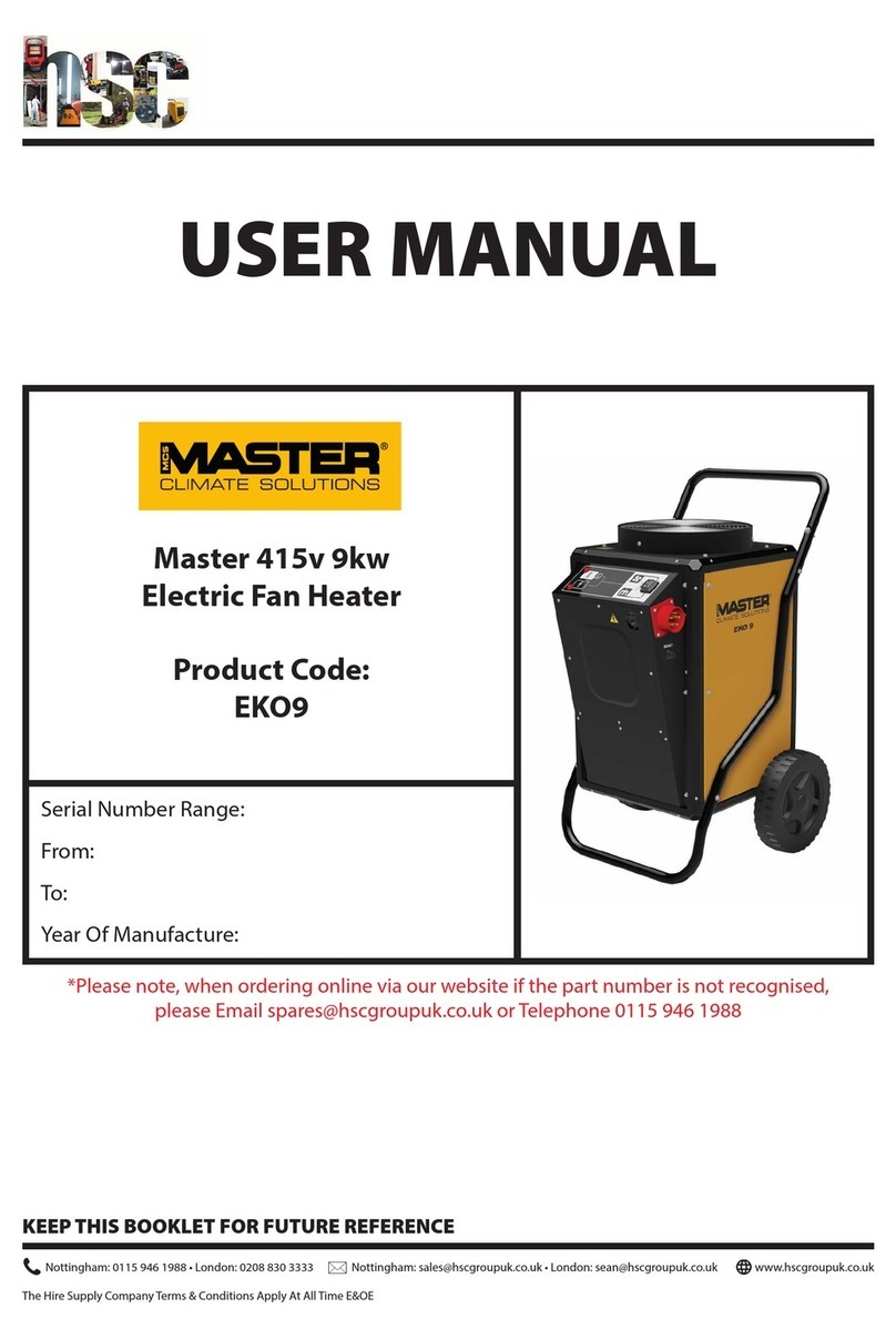
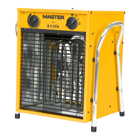
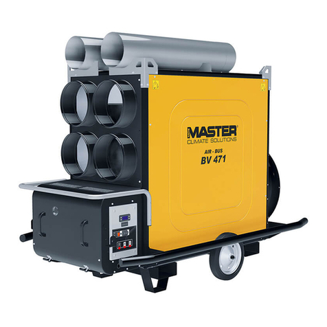
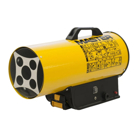
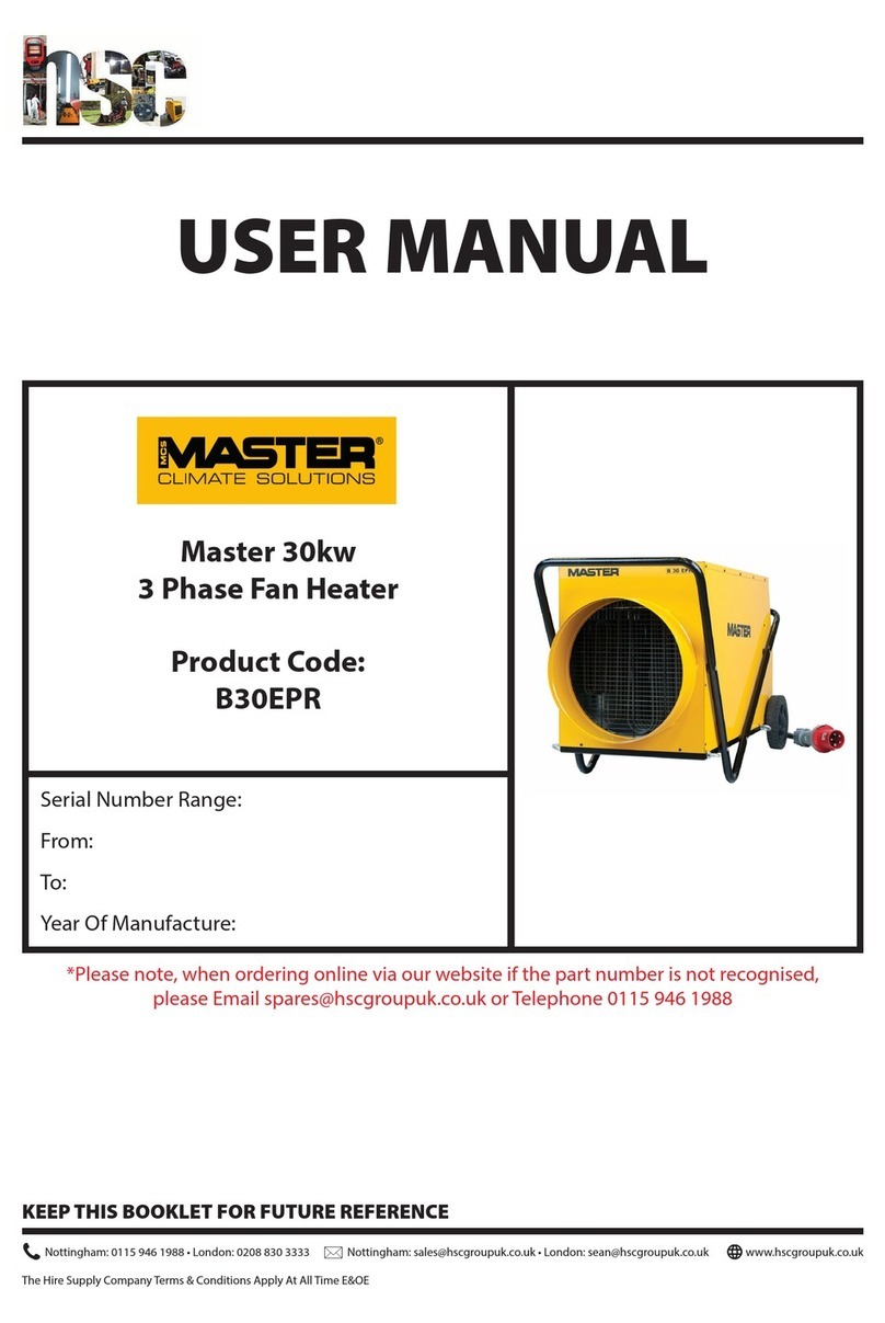
MCS Master BV 170DV Manual

USER MANUAL
Master Dual Voltage
Indirect Oil-Fired Heater
Product Code:
BV170DV
Serial Number Range:
From:
To:
Year Of Manufacture:
*Please note, when ordering online via our website if the part number is not recognised,
please Email spares@hscgroupuk.co.uk or Telephone 0115 946 1988
KEEP THIS BOOKLET FOR FUTURE REFERENCE
Nottingham: 0115 946 1988 • London: 0208 830 3333 Nottingham: [email protected] • London: [email protected]
The Hire Supply Company Terms & Conditions Apply At All Time E&OE
www.hscgroupuk.co.uk

4035.840 Edition 22 Rev. 1
B 130 - B 180 - B 230 - B 230DV - B 360 - B 360DV
BV 69E - BV 69DV - BV 77E - BV 77DV
BV 110E - BV 110DV - BV 170E - BV 170DV - BV 290E - BV 290DV
USER AND MAINTENANCE BOOK
en
LIBRETTO USO E MANUTENZIONE
it
BEDIENUNGS- UND WARTUNGSANLEITUNG
de
MANUAL DE INSTRUCCIONES PARA EL USO Y MANTENIMIENTO
es
MANUEL D’UTILISATION ET DE MAINTENANCE
fr
HANDLEIDING VOOR GEBRUIK EN ONDERHOUD
nl
MANUAL DE USO E MANUTENÇÃO
pt
VEJLEDNING OM BRUG OG VEDLIGEHOLDELSE
da
KÄYTTÖ- JA HUOLTO-OHJE
HEFTE FOR BRUK OG VEDLIKEHOLD
no
ANVÄNDAR- OCH UNDERHÅLLSHANDBOK
sv
INSTRUKCJA OBSŁUGI I KONSERWACJI
pl
РУКОВОДСТВО ПО ЭКСПЛУАТАЦИИ И ТЕХНИЧЕСКОМУ ОБСЛУЖИВАНИЮ
ru
PŘÍRUČKA PRO POUŽITÍ A ÚDRŽBU
cs
HASZNÁLATI ÉS KARBANTARTÁSI KÉZIKÖNYV
hu
PRIROČNIK Z NAVODILI ZA UPORABO IN VZDRŽEVANJE
sl
KULLANIM VE BAKIM K
i
TAPÇIĞI
tr
KNJIŽICA O UPORABI I ODRŽAVANJU
hr
NAUDOJIMO IR PRIEŽIŪROS KNYGELĖ
lt
LIETOŠANAS UN TEHNISKĀS APKOPES GRĀMATIŅA
lv
KASUTUS- JA HOOLDUSJUHEND
et
MANUAL DE UTILIZARE ŞI ÎNTREŢINERE
ro
PRÍRUČKA PRE POUŽITIE A ÚDRŽBU
sk
НАРЪЧНИК ЗА ИЗПОЛЗВАНЕ И ПОДДРЪЖКА
bg
КЕРІВНИЦТВО З ЕКСПЛУАТАЦІЇ Й ТЕХНІЧНОГО ОБСЛУГОВУВАННЯ
uk
KNJIŽICOM O UPOTREBI I ODRŽAVANJU
bs
ΕΓΧΕΙΡΙΔΙΟ ΧΡΗΣΗΣ ΚΑΙ ΣΥΝΤΗΡΗΣΗΣ
el
使用和维护手册
zh
ПАЙДАЛАНУ ЖӘНЕ ТЕХНИКАЛЫҚ ҚЫЗМЕТ КӨРСЕТУ ЖЕТЕКШІЛІГІ
kk

BV 110DV BV 170DV BV 290DV
MAX
34 kW-кВт
29.200 kcal/h-ккал/ч
116.000 Btu/h-БТЕ/ч
49 kW-кВт
42.100 kcal/h-ккал/ч
167.200 Btu/h-БТЕ/ч
85 kW-кВт
73.100 kcal/h-ккал/ч
290.000 Btu/h-БТЕ/ч
1.800 m³/h-м³/ч 1.800 m³/h-м³/ч 3.300 m³/h-м³/ч
2,71 kg/h-кг/ч 3,9 kg/h-кг/ч 6,8 kg/h-кг/ч
DIESEL-HVO100-KEROSENE
дизель-HVO100-керосин
DIESEL-HVO100-KEROSENE
дизель-HVO100-керосин
DIESEL-HVO100-KEROSENE
дизель-HVO100-керосин
65 l-л 65 l-л 105 l-л
~110/240 V-В (-15%÷10%)
50 Hz-Гц
7,5/3,5 A 0,8 kW-кВт
~110/240 V-В (-15%÷10%)
50 Hz-Гц
7,5/3,5 A 0,8 kW-кВт
~110/240 V-В (-15%÷10%)
50 Hz-Гц
9,2/4,6 A 0,8 kW-кВт
61 kg-кг 67 kg-кг 101 kg-кг
0,65 US gal/h 80°S
DANFOSS
1,00 US gal/h 80°S
DANFOSS
1,50 US gal/h 80°S
DANFOSS
1.200 kPa-кПа
12 bar-бар
1.000 kPa-кПа
10 bar-бар
1.200 kPa-кПа
12 bar-бар
IMPORTANT: Please use only one of the following fuels: HVO 100 Biofuel, Diesel B7 and Kerosene.
IMPORTANT: In order to have a correct function you must use an electrical generator in class G3 or more (frequency variation ±1%,
tension variation ±2%). The maximum power of electrical generator must be three time the nominal power of device that you must connect.
TECHNICAL DATA TABLE - TABELLA DATI TECNICI - TECHNISCHE DATENTABELLE - TABLA
DE DATOS TÉCNICOS - TABLEAU DES DONNÉES TECHNIQUES - TABEL TECHNISCHE
GEGEVENS - TABELA DE DADOS TÉCNICOS - TEKNISK DATATABEL - TEKNISTEN TIETOJEN
TAULUKKO - TABELL FOR TEKNISKE DATA - TABELL MED TEKNISKA EGENSKAPER -
TABELA DANYCH TECHNICZNYCH - ТАБЛИЦЕ ТЕХНИЧЕСКИХ ДАННЫХ - TABULKA
TECHNICKÝCH ÚDAJŮ - MŰSZAKI ADATOK TÁBLÁZATA - TEHNIČNI PODATKI - TEKNİK
VERİLER TABLOSUNDA - TABLICI S TEHNIČKIM PODACIMA - TECHNINIŲ DUOMENŲ
LENTELĖJE - TEHNISKO DATU TABULA - TEHNILISTE ANDMETE TABEL - TABELUL CU
DATE TEHNICE - TABUĽKA TECHNICKÝCH ÚDAJOV - ТАБЛИЦА ТЕХНИЧЕСКИ ДАННИ
- ТАБЛИЦІ ТЕХНІЧНИХ ДАНИХ - TABELI SA TEHNIČKIM PODACIMA - ΠΙΝΑΚΙΔΑ ΤΩΝ
ΤΕΧΝΙΚΩΝ ΣΤΟΙΧΕΙΩΝ - 技术参数 - ТЕХНИКАЛЫҚ КӨРСЕТКІШТЕР КЕСТЕСІ

PICTURES - FIGURE - ABBILDUNGEN - FIGURAS - FIGURES - FIGUREN
- FIGURAS - FIGURER - KUVAT - FIGURER - FIGUR - RYSUNKI - РИСУН-
КИ - OBRÁZKY - ÁBRÁK - SLIKE - ŞEKİLLER - SLIKE - PAVEIKSLĖLIAI -
ATTĒLI - JOONISED - IMAGINI - OBRÁZKY - ФИГУРА - МАЛЮНКИ - SLIKE
- ΕΙΚΟΝΕΣ - 图 - СУРЕТТЕР
3
4

5
6
PICTURES - FIGURE - ABBILDUNGEN - FIGURAS - FIGURES - FIGUREN
- FIGURAS - FIGURER - KUVAT - FIGURER - FIGUR - RYSUNKI - РИСУН-
КИ - OBRÁZKY - ÁBRÁK - SLIKE - ŞEKİLLER - SLIKE - PAVEIKSLĖLIAI -
ATTĒLI - JOONISED - IMAGINI - OBRÁZKY - ФИГУРА - МАЛЮНКИ - SLIKE
- ΕΙΚΟΝΕΣ - 图 - СУРЕТТЕР

ABCD
E
F
ABCD
E
7
8
PICTURES - FIGURE - ABBILDUNGEN - FIGURAS - FIGURES - FIGUREN
- FIGURAS - FIGURER - KUVAT - FIGURER - FIGUR - RYSUNKI - РИСУН-
КИ - OBRÁZKY - ÁBRÁK - SLIKE - ŞEKİLLER - SLIKE - PAVEIKSLĖLIAI -
ATTĒLI - JOONISED - IMAGINI - OBRÁZKY - ФИГУРА - МАЛЮНКИ - SLIKE
- ΕΙΚΟΝΕΣ - 图 - СУРЕТТЕР

910
11 12
14
15
110V
240V
240V
110V
240V
110V
13
16
PICTURES - FIGURE - ABBILDUNGEN - FIGURAS - FIGURES - FIGUREN
- FIGURAS - FIGURER - KUVAT - FIGURER - FIGUR - RYSUNKI - РИСУН-
КИ - OBRÁZKY - ÁBRÁK - SLIKE - ŞEKİLLER - SLIKE - PAVEIKSLĖLIAI -
ATTĒLI - JOONISED - IMAGINI - OBRÁZKY - ФИГУРА - МАЛЮНКИ - SLIKE
- ΕΙΚΟΝΕΣ - 图 - СУРЕТТЕР

17 18
19
22
23 24
20
BA
B
A
B
A
C
21
PICTURES - FIGURE - ABBILDUNGEN - FIGURAS - FIGURES - FIGUREN
- FIGURAS - FIGURER - KUVAT - FIGURER - FIGUR - RYSUNKI - РИСУН-
КИ - OBRÁZKY - ÁBRÁK - SLIKE - ŞEKİLLER - SLIKE - PAVEIKSLĖLIAI -
ATTĒLI - JOONISED - IMAGINI - OBRÁZKY - ФИГУРА - МАЛЮНКИ - SLIKE
- ΕΙΚΟΝΕΣ - 图 - СУРЕТТЕР

25 26
27
PICTURES - FIGURE - ABBILDUNGEN - FIGURAS - FIGURES - FIGUREN
- FIGURAS - FIGURER - KUVAT - FIGURER - FIGUR - RYSUNKI - РИСУН-
КИ - OBRÁZKY - ÁBRÁK - SLIKE - ŞEKİLLER - SLIKE - PAVEIKSLĖLIAI -
ATTĒLI - JOONISED - IMAGINI - OBRÁZKY - ФИГУРА - МАЛЮНКИ - SLIKE
- ΕΙΚΟΝΕΣ - 图 - СУРЕТТЕР

NOTE:_______________________________________________________________
______________________________________________________________________
______________________________________________________________________
______________________________________________________________________
______________________________________________________________________
______________________________________________________________________
______________________________________________________________________
______________________________________________________________________
______________________________________________________________________
______________________________________________________________________
______________________________________________________________________
______________________________________________________________________
______________________________________________________________________
______________________________________________________________________
______________________________________________________________________
______________________________________________________________________
______________________________________________________________________
______________________________________________________________________
______________________________________________________________________
______________________________________________________________________
______________________________________________________________________
______________________________________________________________________
______________________________________________________________________
______________________________________________________________________
______________________________________________________________________
______________________________________________________________________
______________________________________________________________________
______________________________________________________________________

en
it
de
es
fr
nl
pt
da
no
sv
pl
ru
cs
hu
sl
tr
hr
lt
lv
et
ro
sk
bg
uk
bs
el
zh
IMPORTANT: READ AND UNDERSTAND THIS MANUAL PRIOR TO
ASSEMBLING, STARTING UP OR CONDUCTING MAINTENANCE ON THIS
HEATER. USING THE HEATER INCORRECTLY CAN CAUSE SERIOUS
INJURY. KEEP THIS MANUAL FOR FURTHER REFERENCE.
1. DESCRIPTION
This series of heaters is particularly suited to
heating medium to large-sized rooms or areas.
The series is divided into direct heaters and
indirect heaters.
Direct heaters (PIC. 1-2) mix hot air with
combustion fumes. For this reason they are
particularly suited for outdoor environments or
areas with high air renewal where there is a
need to heat up, defrost or dry.
Thanks to a heat exchanger, indirect heaters
(PIC. 3-4) separate combustion gases from the
hot air released into the environment. This way
it is possible to introduce a ow of clean hot air
in the area that needs to be heated up and direct
exhaust fumes outside.
These heaters have been designed in line with
the most recent safety, operating and duration
criteria. The safety devices ensure the machine
always operates correctly.
2. SAFETY INFORMATION
WARNINGS
IMPORTANT: This air heater has
been designed for mobile and temporary
professional applications. It has not been
designed for domestic use nor for thermal
comfort of human.
IMPORTANT: This appliance is not
suitable for use by persons (including
children) with reduced physical, sensory
and mental capacities or with lack of ex-
perience or knowledge unless supervised
by a person responsible for their safety.
Children must be supervised to make sure
they do not play with the appliance.
DANGER: Suocation by carbon
monoxide can be fatal.
The rst symptoms of suocation by carbon
monoxide are similar to those of u with
headache, light-headedness and/or nausea.
These symptoms could be caused by the
faulty functioning of the heater. IF THESE
SYMPTOMS OCCUR, GO OUTDOORS
IMMEDIATELY and have the heater repaired
by a technical service centre.
►►2.1. REFUELLING:
►2.1.1. Personnel appointed to carry out re-
fuelling must be qualied and fully familiar
with this manual and current regulations
on how to refuel heaters safely.
►2.1.2. Only use the type of fuel specied
on the heater’s identication plate.
►2.1.3. Before refuelling, turn o the heater
and wait for it to cool down.
►2.1.4. The fuel storage deposit tanks must
be located in a separate facility or build-
ing.
►2.1.5. All fuel tanks must be kept at a mini-
mum distance from the heater, in accor-
dance with current safety regulations.
►2.1.6. Fuel must be stored in areas where
the oor surface does not allow under-
neath dripping, or any other leakage which
may ignite the fuel.
►2.1.7. Fuel must be stored in accordance
with current safety regulations.
►►2.2. SAFETY:
►2.2.1. Never use the heater in areas with
petrol, paint solvents or other highly am-
mable vapours.
►2.2.2. Comply with all local legislation and
current regulations when using the heater.
►2.2.3. Heaters used near tarpaulins, cur-
tains or other similar covering materials
must be kept at a safe distance. It is ad-
vised to use re-proof covering material.
►2.2.4. Only use heaters in well-ventilated
areas. Set-up a suitable open and venti-
lated area, with the purpose of introduc-
ing fresh air from outdoors, in compliance
with the current safety standards.
►2.2.5. Heaters must be powered only with
the correct voltage and frequency values
as specied on the heater’s identication
plate.
►2.2.6. Only use suitable earthed extension
cable.
►2.2.7. The recommended safety distances
between heaters and ammable substanc-
es are: front output = 2,5 m; side/top/rear
output = 1,5 m.
►2.2.8. Avoid re hazards by placing the hot
or functioning heater on a at level sur-
face.

en
it
de
es
fr
nl
pt
da
no
sv
pl
ru
cs
hu
sl
tr
hr
lt
lv
et
ro
sk
bg
uk
bs
el
zh
►2.2.9. Always keep animals at a safe dis-
tance.
►2.2.10. Disconnect the heater from the
main power supply when not in use.
►2.2.11. When controlled by a thermostat,
the heater can turn on at any time.
►2.2.12. Never use the heater in frequently
used rooms or in bedrooms.
►2.2.13. Never block the heater’s air inlet
(rear) or the air outlet (front).
►2.2.14. Never move, handle, refuel or con-
duct maintenance on the heater when it is
hot or when connected to the power sup-
ply or when in operation.
►2.2.15. Only use original kit/hose to direct
air ow (in and out) (where applicable).
►2.2.16. Keep heater’s hot parts at as safe
distance from inammable materials (in-
cluding the power supply cable).
►2.2.17. If the power supply cable is dam-
aged, it must be replaced by a technical
service centre, in order to prevent further
risks.
3. UNPACKING
WARNING: The packaging material is not
a toy. Keep the plastic bag out of the reach
of children; danger of suocation!
►3.1. Remove all packaging materials used to
wrap and deliver the heater and dispose them
in compliance with current regulations.
►3.2. If the heater is placed on a moving
platform, make sure it is moved gently.
►3.3. Check for any damage that might have
happened during transport. If the heater looks
damaged, immediately inform the dealer from
which it was purchased.
4. ASSEMBLY
These heaters are tted with wheels, a handle
and a chimney depending on the model (PIC.
5-6). These parts, which come with the relative
nuts and bolts, are in the heater’s packaging.
5. FUEL
WARNING: The heater only works with
HVO 100 Biofuel, Diesel B7 or Kerosene.
In order to avoid explosions or any re hazards,
use only diesel or kerosene fuel.
Never use petrol, naphtha, paint solvents, alco-
hol or any other highly inammable fuels.
Non-toxic, anti-freeze additives can be used in
case of very low temperatures.
It is advisable to use winter diesel below 5°C.
6. OPERATING PRINCIPLES
A. Combustion chamber and burner, B. Fan,
C. Motor, D. Pump, E. Tank, F. Chimney
(indirect models).
The pump draws fuel from the tank and brings
it to the operating pressure. The fuel is brought
to the nozzle that sprays it into the combustion
chamber. The combustion is carried out with a
mix of air and fuel and the ow of air generated
is pushed outside via the rotation of the fan.
In direct models (PIC. 7) combustion products
ow together with heated air. In indirect models
(PIC. 8) combustion products are directed
outside through the chimney. A series of
sensors connected to an electronic control
board constantly keep the correct operation of
the heater monitored and stops the cycle in the
event of anomalies.
7. OPERATION
WARNING: Carefully read the “SAFETY
INFORMATION” before switching on the
heater.
IMPORTANT: In models with dual voltage
(...DV), check the position of the dual
voltage switch (220-240V / 110-120V) (PIC.
9). If the voltage set on the heater does not
correspond to the mains supplied voltage,
it is necessary to adjust it. Unscrew the
two securing screws of the cover (PIC.
10), adjust/press the switch to the correct
voltage (PIC. 11) and reassemble the cover
(PIC. 12).
VERIFY THE CONGRUENCE BETWEEN
POWER TENSION SUPPLY, SETTING OF
DUAL VOLTAGE SWITCH AND TYPE OF
PLUG, BECAUSE IMPROPER USE MAY
CAUSE DAMAGE TO THE HEATER.
►►7.1. SWITCHING ON THE HEATER:
►7.1.1. Please follow the safety instructions.
►7.1.2. Check if there is enough fuel in the tank.
►7.1.3. Close the tank cup (PIC. 13).
►7.1.4. Connect the power supply plug to the
mains electricity (PIC. 14) (SEE VOLTAGE IN
THE “TECHNICAL DATA TABLE”).
►7.1.5. Set the “I/0” switch to “I” (PIC. 15). The
heater should turn on within a few seconds. If
the heater does not start, refer to paragraph
“12. TROUBLESHOOTING”.
►7.1.6. For models with a room thermostat,
check the position of the knob (PIC. 16).
PLEASE NOTE: IF THE HEATER SWITCHES
OFF DUE TO LACK OF FUEL, TOP UP THE

en
it
de
es
fr
nl
pt
da
no
sv
pl
ru
cs
hu
sl
tr
hr
lt
lv
et
ro
sk
bg
uk
bs
el
zh
TANK AND RESET THE HEATER (SEE PAR.
7.2.).
IMPORTANT: In indirect models,
combustion products are directed outside
through suitable chimney. CARRY OUT
THE CHIMNEY IN ACCORDANCE WITH
CURRENT SAFETY REGULATIONS AND
FOLLOW THE INSTRUCTIONS IN THE
RELEVANT SECTION OF THE MANUAL.
►►7.2. RESETTING THE HEATER:
The appliance stops when an anomaly occurs.
The reset button turns on with a steady red light
(PIC. 17), it means the heater needs to be reset.
To reset the heater, press the reset button all
the way down (PIC. 18). Identify and remove
the cause that stopped the appliance (for
instance, obstruction of air intake and/or outlet,
total block of the fan, etc.). Please contact an
appointed service center for assistance in case
it is impossible to solve the problem.
►►7.3. SWITCHING OFF THE HEATER:
Set the “I/0” button to “0” (PIC. 19). Flames
extinguish and the fan keeps on working until
the combustion chamber has fully cooled down.
Do not pull the plug out until the cooling
cycle has totally ended.
8. CLEANING THE FILTERS
THE FILTERS MAY NEED TO BE CLEANED
DEPENDING ON THE QUALITY OF THE
FUEL USED.
►►8.1. FUEL TANK FILTER (PIC. 20):
►8.1.1. Remove tank (A) cap.
►8.1.2. Take out the lter (B) from the tank.
►8.1.3. Clean the lter (B) with clean fuel,
without damaging it.
►8.1.4. Put the lter (B) back in the tank.
►8.1.5. Close cap (A).
►►8.2. INTAKE FILTER, (PIC. 21)
DEPENDING ON THE MODEL:
►8.2.1. Take out the lter (A).
►8.2.2. Remove the pipe-clamping straps (B).
►8.2.3. Take out the pipes (C).
►8.2.4. Replace the lter (A) with an original
spare part.
►8.2.5. Put the pipes (C) back.
►8.2.6. Put the pipe-clamping straps (B) back.
►8.2.7. Put the lter (A) back into its original
position.
►►8.3. INTAKE FILTER, (PIC. 22)
DEPENDING ON THE MODEL:
►8.3.1. Remove the cup (A).
►8.3.2. Take out the lter (B) from the cup.
Keep gaskets for later use.
►8.3.3. Clean the lter (B) with clean fuel,
without damaging it.
►8.3.4. Put the lter (B) back in the cup.
►8.3.5. Put the glass (A) back on and
reassemble the gaskets correctly.
►►8.4. FUEL PUMP FILTER:
See the preventive maintenance schedule.
9. STORAGE AND TRANSPORT
WARNING: Before moving the appliance,
the heater must be stopped (SEE PAR.
7.3.) and disconnected from the power
supply by pulling out the plug (PIC. 23),
wait for a complete cool down and close
the tank cap properly to prevent fuel
leakage. Keep the heater in horizontal and
stable position during transport.
IN ORDER TO KEEP THE HEATER IN
THE BEST POSSIBLE CONDITIONS, WE
RECOMMEND TO FOLLOW THE BELOW
PROCEDURE:
►9.1. Empty the fuel by removing the drain
cap at the bottom of the tank (PIC. 24-25).
Dispose the fuel in an appropriate container
in accordance with the current safety
regulations.
►9.2. To remove any residual remaining, pour
clean fuel and rinse the tank again.
►9.3. Close the drain cap and the tank cap.
►9.4. In order to keep the heater in the best
possible conditions, we recommend placing it
in a dry and safe place.
10. CONNECTING THE ROOM
THERMOSTAT
In models with a thermostat connection, remove
the cap connected to the appliance and connect
the room thermostat (optional) (SEE PIC. 26-
27).

en
it
de
es
fr
nl
pt
da
no
sv
pl
ru
cs
hu
sl
tr
hr
lt
lv
et
ro
sk
bg
uk
bs
el
zh
WARNING: BEFORE PERFORMING ANY MAINTENANCE OR REPAIRS, UNPLUG HEATER
FROM THE MAIN POWER SUPPLY AND MAKE SURE THE HEATER IS TOTALLY COOL.
11. PREVENTIVE MAINTENANCE SCHEDULE
COMPONENT MAINTENANCE FREQUENCY MAINTENANCE PROCEDURE
Fuel tank Clean once a year or as required Empty and rinse the tank with clean
fuel (SEE PAR. 9.)
Filters Clean or replace once a year or as
required (make sure they are intact)
Clean the lters (SEE PAR. 8.)
Fuel pump lter Clean or replace once a year or as
required (make sure they are intact)
Contact a service centre
Electrodes Clean as required Contact a service centre
Fan Clean as required Contact a service centre
Combustion
chamber
Clean as required Contact a service centre
12. TROUBLESHOOTING
PROBLEM POSSIBLE CAUSE POSSIBLE SOLUTION
The heater does
not start or does
not operate
1. Starter switch in “OFF” (0)
position
2. No power supply
3. Power supply cable
interrupted
4. Electronic control board
blocked or malfunctioning
5. Incorrect setting of the room
thermostat (if present)
6. No fuel
7. External substances or dirt
in the fuel circuit
1. Set starter switch to “ON” (|) position (PIC.
15)
2a. Insert the power plug into the mains
socket correctly (PIC. 14)
2b. Check voltage of your electric supply
system
2c. In dual voltage models (…DV) (PIC.
9), set the switch to the correct voltage
position required
3. Contact a service centre
4a. Reset the heater (SEE PAR. 7.2.)
4b. Contact a service centre
4c. Contact a service centre
5. Set the room thermostat to a temperature
higher than the working environment
temperature (PIC. 16)
6. Top up fuel and reset heater
7a. Empty, rinse and rell the tank
7b. Rinse the lters (SEE PAR. 8.)
7c. Contact a service centre
Smoke while
operating
1. External substances or dirt
in the fuel circuit
2. Obstructed inlet air vent
1a. Empty and rell the tank with clean fuel
1b. Rinse fuel lters
1c. Contact a service centre
2. Remove all air vent obstructions
The heater does
not turn o
1. Faulty electronic system 1. Contact a service centre

FLUE CONNECTIONS DIAGRAM - SCHEMA DI FISSAGGIO - HINWEISE
FÜR DEN SCHORNSTEINBAU - ESQUEMA DE FIJACIÓN - SCHÉMA DE
FIXAGE - BEVESTIGINGSSCHEMA - ESQUEMA DE FIXAÇÃO - FASTSPÆN-
DINGSSKEMA - KIINNITYSKAAVIO - FESTESKJEMA - MONTERINGSSCHE-
MA - SCHEMAT MOCOWANIA - СХЕМА КРЕПЛЕНИЯ - SCHEMAT MONTAŻU
PRZYŁĄCZA KOMINOWEGO - RÖGZÍTÉSI RAJZ - SHEMA ZA PRITRJEVANJE
- SABİTLEME ŞEMASI - SHEMA PRIČVRŠĆIVANJA - TVIRTINIMO SCHEMA
- NOSTIPRINĀŠANAS SISTĒMA - KINNITAMISE SKEEM - SCHEMĂ DE FIXA-
RE - SCHÉMA ZAPOJENIA DYMOVODU - СХЕМА ЗА ЗАКРЕПВАНЕ - СХЕМА
КРІПЛЕННЯ - ŠEMA PRIČVRŠĆIVANJA - ΣΧΗΜΑ ΣΤΕΡΕΩΣΗΣ - 固定装置示意图 -
БЕКІТУ СҮЛБЕСІ
A
AØ > 120 mm-мм BV 69...
BV 77...
Ø > 150 mm-мм BV 110...
BV 170...
BV 290...

DUCTING INSTRUCTIONS - INDICAZIONI PER LA CANALIZZAZIONE - HINWEI-
SE FÜR DEN SCHORNSTEINBAU - INDICACIÓN PARA LA CANALIZACIÓN - INDI-
CATIONS POUR LA CANALISATION - AANWIJZINGEN VOOR DE KANALISERING
- INDICAÇÕES PARA A CANALIZAÇÃO - ANVISNINGER TIL KANALISERING
- KANAVOINTIOHJEET - INDIKASJONER FOR KANALISERING - ANVISNINGAR
FÖR KANALISERING - ZALECENIA ODNOŚNIE MONTAŻU INSTALACJI KOMI-
NOWEJ - УКАЗАНИЯ ДЛЯ КАНАЛИЗАЦИИ - SCHÉMA ZAPOJENÍ KOUŘOVODU
- ÚTMUTATÓ CSŐRENDSZER KIÉPÍTÉSÉHEZ - NAVODILA ZA KANALIZIRANJE
- KANALİZASYON TALİMATLARI - INDIKACIJE ZA SPROVOĐENJE U CIJE-
VI - NURODYMAI DĖL ORO IŠLEIDIMO - CAURUĻVADU INDIKĀCIJAS - TORU
PAIGALDAMISE JUHEND - INDICAŢII PRIVIND DIRECŢIONAREA - SCHÉMA
ZAPOJENIA DYMOVODU - УКАЗАНИЯ ЗА КАНАЛИЗАЦИЯТА - ВКАЗІВКИ З
ВИКОНАННЯ КАНАЛІВ - INDIKACIJE ZA SPROVOĐENJE U CIJEVI - ΟΔΗΓΙΕΣ
ΓΙΑ ΤΗ ΔΙΟΧΕΤΕΥΣΗ - 管道设置说明 - КӘРІЗ ЖҮЙЕСІНЕ АРНАЛҒАН НҰСҚАУЛАР
AB
C
D
B
AB
C
D
E
A> 1 m-м
B≥ 1 m-м
CAs short as possible - Il piu corto possibile - Die kürzestmögliche - Tan corto como sea posible - Le plus
court possible - Zo kort mogelijk - O mais curto possível - Så kort som muligt - Mahdollisimman lyhyt - Kor-
test mulig - Så kort som möjligt - Możliwie jak najkrótszy - Nasadka kominowa - Как можно короче - Co
možná nejkratší - Lehető legrövidebb - Najkrajše - Mümkün olduğunca kısa - Što su kraće moguće - Kiek
įmanoma trumpesnis - Pēc iespējas īsākas - Võimalikult lühike - Cât mai scurt posibil - Pokiaľ možno čo
najkratšie - Възможно най-късият - Найбільш короткий шлях, по можливості - Što su kraće moguće -
Όσο πιο μικρό γίνεται - 尽量短 - Мүмкіндігінше қысқарақ
D> 5°
EWindproof terminal - Terminale antivento - Windschutzanschluss - Terminal antiviento - Terminal anti-
vent - Windkerend eindpunt - Terminal antivento - Vindafskærmning - Tuulenpitävä terminaali - Vindtett
terminal - Vindskyddat rörslut - Nasadka kominowa - Ветрозащитный наконечник - Koncový díl proti
větru - Szélálló csatlakozás - Terminal proti vetru - Rüzgar geçirmez terminal - Završni dio otporan na
vjetar - Apsaugojantis nuo vėjo terminalas - Vēja aizsardzības termināls - Tuulekindel tagumine osa - Ter-
minal anti-vânt - Koncový diel proti vetru - Терминално устройство за предпазване от вятър - Кінцевий
пристрій для захисту димоходу від вітру - Završni dio otporan na vjetar - Αντιανεμικό τερματικό - 防风
终端 - Желден қорғайтын ұштық

ELECTRODES REGULATION - REGOLAZIONE ELETTRODI - REGULIERUNG DER
ELEKTRODEN - REGULACIÓN DE LOS ELECTRODOS - REGULATION DES ELEC-
TRODES - AFSTELLING ELEKTRODEN - REGULAÇÃO DE ELÉTRODOS - REGULE-
RING AF ELEKTRODER - ELEKTRODIEN SÄÄTÖ - REGULERING AV ELEKTRODER
- ELEKTRODREGLERING - REGULACJA ELEKTROD - РЕГУЛЯЦИЯ ЭЛЕКТРОДОВ
-NASTAVENÍ ELEKTROD - AZ ELEKTRÓDÁK BEÁLLÍTÁSA - NASTAVITEV ELE-
KTROD - ELEKTROT AYARI - REGULIRANJE ELEKTRODA - ELEKTRODŲ REGU-
LIAVIMAS - ELEKTRODU REGULĒŠANA - ELEKTROODIDE REGULEERIMINE
- REGLAREA ELECTROZILOR - NASTAVENIE ELEKTRÓD - РЕГУЛИРАНЕ ЕЛЕК-
ТРОДИ - РЕГУЛЮВАННЯ ЕЛЕКТРОДОВ - KONTROLA ELEKTRODE - ΡΥΘΜΙΣΗ
ΗΛΕΚΤΡΟΔΙΩΝ -
电极规定
电极规定 - ЭЛЕКТРОДТАРДЫ РЕТТЕУ
A
B
C
A3 mm-мм
B6 mm-мм
C3 mm-мм

COMBUSTION AIR DAMPER ADJUSTMENT - REGOLAZIONE SERRANDA
ARIA COMBURENTE - LUFTEINLASSREGISTER EINSTELLUNG - REGULA-
CIÓN DE LA COMPUERTA DE AIRE COMBURENTE - RÉGLAGE DU VOLET AIR
COMBURANT - AFSTELLING REGELKLEP VERBRANDINGSLUCHT - REGU-
LAÇÃO DO REGULADOR DE VAZÃO DO AR COMBURENTE - REGULERING AF
LUFTINDTAGSDÆMPNING - PALAMISILMAN SULKIMEN SÄÄTÖ - REGULE-
RING BRANNGASSPJELD - REGLERING AV FÖRBRÄNNINGSLUFTENS SPJÄLL
- REGULACJA SZCZELINY POWIETRZNEJ - РЕГУЛИРОВКА ЗАСЛОНКИ
ВОСПЛАМЕНЯЮЩЕГОСЯ ВОЗДУХА - NASTAVENÍ KLAPKY SPALOVACÍHO
VZDUCHU - ÉGÉSI LEVEGŐ ZSALU SZABÁLYOZÁSA - NASTAVITEV LOPUTE
ZGOREVALNEGA ZRAKA - YANMA HAVASI SÜRGÜSÜ AYARI - PRILAGODBA
ZAKLOPA ZRAKA ZA IZGARANJE - DEGIMO PRODUKTŲ SKLENDĖS RE-
GULIAVIMAS - GAISA IEPLŪDES AIZVERES REGULĒŠANA - PÕLEMISÕHU
AVA REGULEERIMINE - REGLAREA CLAPETEI PENTRU AERUL DE COMBU-
STIE - NASTAVENIE KLAPKY SPAĽOVACIEHO VZDUCHU - РЕГУЛИРАНЕ
НА ЖАЛУЗИЙНАТА РЕШЕТКА ЗА ГОРИВЕН ВЪЗДУХ - РЕГУЛЮВАННЯ
ЗАСЛІНКИ ДЛЯ ПОВІТРЯ, ЩО ПІДТРИМУЄ ГОРІННЯ - PRILAGOĐAVANJE
ZAKLOPA ZRAKA ZA SAGORIJEVANJE - ΡΥΘΜΙΣΗ ΤΟΥ ΚΛΕΙΣΤΡΟΥ ΑΕΡΑ
ΚΑΥΣΗΣ - 助燃气体门窗调节
- ЖАНАТЫН АУА ЗАСЛОНКАЛАРЫН РЕТТЕУ
A
A6 mm-мм BV 69...
BV 77...
7 mm-мм BV 110...
14 mm-мм BV 290...
16 mm-мм B 230...
25 mm-мм B 360...
20 mm-мм BV 170...

B 230 - B 360 - BV 110E - BV 170E - BV 290E
B 230DV - B 360DV - BV 110DV - BV 170DV - BV 290DV
WIRING DIAGRAMS - SCHEMI ELETTRICI - SCHALTPLÄNE - ESQUEMAS
ELÉCTRICOS - SCHEMAS ELECTRIQUES - ELEKTRISCHE SCHEMA’S - ESQUE-
MAS ELÉCTRICOS - ELEKTRISKE SKEMAER - SÄHKÖKAAVIOT - KOPLINGS-
SKJEMA - ELEKTRISKA KOPPLINGSSCHEMAN - SCHEMATY ELEKTRYCZNE
- ЭЛЕКТРИЧЕСКИЕ СХЕМЫ - ELEKTRICKÁ SCHÉMATA - VILLANYBEKÖTÉSI
RAJZOK - ELEKTRIČNE SHEME - ELEKTR EMALARI - ELEKTRIČNE SH-
EME - ELEKTROS SCHEMOS - ELEKTRISKĀS SHĒMAS - ELEKTRISKEEMID
- SCHEME ELECTRICE - ELEKTRICKÉ SCHÉMY - ЕЛЕКТРИЧЕСКИ СХЕМИ
- ЕЛЕКТРИЧНІ СХЕМИ - ELEKTRIČNE ŠEME - ΗΛΕΚΤΡΙΚΑ ΣΧΕΔΙΑ - 线路图
-
ЭЛЕКТРЛІ СҮЛБЕЛЕР

TS Overheat thermostat - Termostato di sicurezza - Sicherheitsthermostat - Termostato de seguridad - Thermostat
de sécurité - Veiligheidsthermostaat - Termóstato de segurança - Sikkerhedstermostat - Turvatermostaatti -
Sikkerhetstermostat - Säkerhetstermostat - Termostat bezpieczeństwa - Термостат безопасности - Bezpečnostní
termostat - Biztonsági termosztát - Varnostni termostat - Emniyet termostatı - Sigurnosni termostat - Apsauginis
termostatas - Drošības termostats - Turvatermostaat - Termostat de siguranţă - Varnostni termostat - Предпазен
термостат - Термостат безпеки - Bezbjednosni termostat - Θερμοστάτης ασφαλείας - 安全调温器 - Қауіпсіздік
термостаты
EV Solenoid valve - Elettrovalvola - Elektroventil - Electroválvula - Électrovalve - Elektroklep - Eletroválvula -
Magnetventil - Solenoidiventtiili - Magnetventil - Magnetventil - Zawór elektromagnetyczny - Соленоид - Elektrický
ventil - Mágnesszelep - Elektromagnetni ventil - Elektrovalf - Električni ventil - Elektrinis vožtuvas - Elektrovārsts -
Solenoidventiil - Electrovalvă - Elektrický ventil - Електроклапан - Електроклапан - Električni ventil - Ηλεκτροβαλβίδα
- 电磁阀 - Соленоид
IG Transformer - Trasformatore - Transformator - Transformador - Transformateur - Transformator - Transformador - Tran-
sformer - Muuntaja - Transformator - Transformator - Transformator - Трансформатор - Transformátor - Transzformátor
- Transformator - Transformatör - Transformator - Transformatorius - Trasformators - Trafo - Transformator - Tran-
sformátor - Трансформатор - Трансформатор - Transformator - Μετασχηματιστής - 变压器 - Трансформатор
IN Switch - Interruttore - Schalter - Interruptor - Interrupteur - Schakelaar - Interruptor - Afbryder - Katkaisin - Bryter
- Brytare - Włącznik - Включатель - Vypínač - Kapcsoló - Stikalo - Açma kapama düğmesi - Prekidač - Jungiklis -
Slēdzis - Lüliti - Întrerupător - Vypínač - Прекъсвач - Вимикач - Prekidač - Διακόπτης - 开关 - Қосқыш
RRelay - Relè - Relais - Relé - Relais - Relais - Relé - Relæ - Rele - Relè - Relä - Przekaźnik - Реле - Relé - Relé - Relè
- Röle - Relej - Relė - Relejs - Relee - Releu - Relé - Реле - Реле - Relej - Ρελέ - 继电器 - Relay
MMotor - Motore - Motor - Motor - Moteur - Motor - Motor - Motor - Moottori - Motor - Motor - Silnik - Двигатель - Motor
- Motor - Motor - Motor - Motor - Variklis - Dzinējs - Mootor - Motor - Motor - Двигател - Двигун - Motor - Κινητήρας
- 电机 - Тежегіш
FPH Fuel pre-heater - Filtro pre-riscaldo - Vorwärmlter - Filtro pre-calentamiento - Filtre préchauage - Filter voorverwar-
ming - Filtro pré-aquecido - Forvarmningslter - Esilämmityksen suodatin - Filter forvarming - Föruppvärmningslter
- Podgrzewacz paliwa z ltrem - Фильтр предварительного нагрева - Filtr předehřevu - Előmelegítő szűrő - Filter
za pred-ogrevanje - Ön ısıtma ltresi - Filtar za predzagrijavanje - Pirminio šildymo ltras - Iepriekšējās sildīšanas
ltrs - Eelsoojenduse lter - Filtru pre-încălzire - Filter predohrevu - Филтър за предварително загряване - Фільтр
попереднього нагрівання - Filter za predzagrijavanje - Φίλτρο προθέρμανσης - 预热过滤装置 - Алдын ала фильтрі
FU Fuse - Fusibile - Schmelzsicherung - Fusibile - Fusée - Veiligheid - Fusível - Sikring - Sulake - Fuse - Säkring -
Bezpiecznik - Предохранитель - Pojistka - Biztosíték - Fuse - Sigorta - Osigurač - Saugiklių - Drošinātājs - Kaitse
- Siguranţă - Poistka - Предпазител - Запобіжник - Fuse - Ασφάλεια - 保险丝 - Сақтандырғыш
TA Room thermostat - Termostato ambiente - Raumthermostat - Termostato ambiente - Thermostat d’ambiance -
Omgevingsthermostaat - Termóstato ambiente - Rumtermostat - Huonetermostaatti - Romtermostat - Rumstermostat
- Termostat pomieszczeniowy - Комнатный термостат - Termostat prostředí - Szobatermosztát - Sobni termostat -
Oda termostatı - Ambijentalni termostat - Aplinkos termostatas - Vides termostats - Ümbritseva keskkonna termostaat
- Termostat ambiental - Termostat prostredia - Ресет - Термостат температури зовнішнього середовища -
Ambijentalni termostat - Θερμοστάτης περιβάλλοντος - 温控器 - Бөлме термостаты
FO Photoresistance - Fotoresisteza - Fotowiderstand - Fotorresistencia - Photorésistance - Fotoweerstand - Foto-resis-
tência - Fotomodstand - Valovastus - Fotomotstand - Fotomotstånd - Fotokomórka - Фоторезистор - Fotoelektrický
odpor - Fotócella ellenállás - Fotoupor - Fotorezistans - Fotootpornost - Fotorezistorius - Fotorezistors - Fototakisti
- Fotorezistenţă - Fotoelektrický odpor - Фоторезистор - Розпалювач - Fotootpornik - Φωτοαντίσταση - 光电感应
器 - Фоторезистор
FR Filter noise - Filtro rete - Netzlter - Filtro red - Filtre réseau - Netlter - Filtro de rede - Netværkslter - Verkon suodatin
- Nettlter - Nätlter - Filtr sieciowy - Сетевой фильтр - Síťový ltr - Hálózati szűrő - Mrežni lter - Ağ ltresi - Filtar
mreže - Tinklo ltras - Filtru tīkls - Võrgu lter - Filtru reţea - Sieťový lter - Филтър мрежа - Мережний фільтр - Filter
mreže - Φιλτρο δικτυου - 过滤器网 - Желі фильтрі
LLine - Linea - Leitung - Línea - Ligne - Lijn - Linha - Linje - Linja - Linje - Linje - Przewód fazowy - Линия - Linka - Sor
- Linija - Hat - Linija - Linija - Līnija - Liin - Linie - Linka - Линия - Фаза - Linija - Γραμμή - 线 - Сызық
NNeutral - Neutro - Nullleiter - Neutro - Neutre - Neutraal - Neutro - Neutral - Neutraali - Nøytral - Noll - Przewód nautral-
ny - Нейтраль - Neutrální - Semleges - Nevtralni vod - Nötr - Neutralna - Neutralus - Neitrāls - Neutraal - Nul - Neutrál
- Неутрално - Нейтраль - Neutralna - Ουδέτερο - 零线 - Нейтраль
ST Dual-voltage switch - Interruttore cambiatensione - Spannungswahlschalter - Interruptor de cambio de tensión - In-
terrupteur changeur de tension - Schakelaar voor omschakeling spanning - Interruptor para modicar a tensão -
Spændingsvælger - Jännitteen vaihdon kytkin - Bryter spenningsvalg - Spänningsomkopplare - Przełącznik napięcia
- Переключатель напряжения - Přepínač napětí - Feszültségváltó kapcsoló - Stikalo za spremembo napetosti - Ge-
rilim değiştirme düğmesi - Prekidač za promjenu napona - Įtampos keitimo jungiklis - Sprieguma selektora slēdzis
- Pinge reguleerimise lüliti - Întrerupător de schimbare a tensiunii - Prepínač napätia - Прекъсвач за смяна на
напрежение - Перемикач напруги - Prekidač za promjenu napona - Διακόπτης αλλαγής τάσης - 电压交换开关 -
Кернеуді ауыстырғыш
AT Autotransformer - Autotrasformatore - Autotransformator - Autotransformador - Autotransformateur - Autotran-
sformator - Autotransformador - Autotransformer - Automaattimuuntaja - Autotransformator - Autotransformator
- Autotransformator - Автотрансформатор - Autotransformátor - Autotranszformátor - Autotransformator - Oto-
transformatör - Autotransformator - Autotransformatorius - Autotrasformators - Autotrafo - Autotransformator - Auto-
transformátor - Автотрансформатор - Автотрансформатор - Autotransformator - Αυτομετασχηματιστής - 自动转换
器 - Автотрансформатор
This manual suits for next models
15
Table of contents
Other MCS Master Heater manuals

MCS Master
MCS Master B 35CEL Manual

MCS Master
MCS Master BLP 17M DC Manual
MCS Master
MCS Master EKO 3 Manual

MCS Master
MCS Master B3 EPB Manual

MCS Master
MCS Master B 18 EPR Manual

MCS Master
MCS Master BLP 17M DC Manual

MCS Master
MCS Master XL 9ER User manual
MCS Master
MCS Master B 2 PTC Manual

MCS Master
MCS Master BLP 33ET Manual

MCS Master
MCS Master 2 EPB User manual