MCS Master XL 9ER User manual

Operating manual - Libretto uso e manutenzione - Bedienungsanleitung - Manual de Uso y Mantenimiento -
Manuel d’instructions - Handleiding voor gebruik en onderhoud - Brug- og vedligeholdelsesmanuale - Instrukcja obsługi - Ekspluatâcijas
Instrukcija - Kasutus- ja hooldusjuhend - Návod k obsluze - Használati utasítás - Instrucţiunile de utilizare - Инструкция за експлоатация
- Инструкция по обслуживанию - Käyttö- ja huolto-ohje - Manual for bruk og vedlikehold
►en - Radiant hot air heater
►it - Generatore d’aria calda ad infrarossi
►de - Infrarotheizgerät
►es - Generador de calor por Infrarrojos
►fr - Générateur de chaleur à l’infrarouge
►nl - Infrarood warmeluchtgenerator
►da - Varmluft generator med infrarøde stråler
►pl - Promiennikowa nagrzewnica powietrza
►lv - Karstâ gaisa izstarotâjs
►et - Kiirgus-õhusoojendi
►cs - Naftové infračervené topidlo
►hu - Légbefúvós hősugárzó
►ro - Radiator infrarosu
►bg - Инфрачервен въздушен отоплител
►ru - Инфракрасный нагреватель воздуха
► - Infrapuna kuumailmageneraattori
►no - Infrarød stråleovn
XL 9ER - XL 9SR
4117.399
Edition 14
Rev. 05
►en - IMPORTANT: Be sure to read and understand this operating manual before assembling, the set up and functioning or the maintenance of this heater. The misuse of this heater
can cause serious injuries. Conserve this manual for future reference. ►it - IMPORTANTE: Leggere e comprendere questo manuale operativo prima di effettuare l’assemblaggio, la
messa in funzione o la manutenzione di questo riscaldatore. L’uso errato del riscaldatore può causare lesioni gravi. Conservare questo manuale a titolo di futuro riferimento. ►de -
WICHTIG: Lesen und verstehen Sie dieses Handbuch vor der Montage, der Inbetriebnahme oder der Wartung dieses Heizgerätes. Falscher Gebrauch des Heizgerätes kann zu schweren
Schäden führen. Bewahren Sie dieses Handbuch für zukünftiges Nachschlagen auf. ►es - IMPORTANTE: Leer atentamente este manual de Uso y Mantenimiento, antes de utilizar por
primera vez este equipo, prestando mucha atención a todas las recomendaciones indicadas. El uso inadecuado del calentador, puede causar daños graves a personas, animales o
cosas. Conservar este manual en lugar seguro y siempre a disposición para futuras consultas. ►fr - IMPORTANT: Lire attentivement et comprendre ce manuel avant d’effecteur l’as-
semblage, la mise en marche ou l’entretien du réchauffeur. Le mauvais usage de celui-ci peut provoquer de graves lésions. Conserver ce manuel comme futur objet de référence. ►nl -
BELANGRIJK: Bestudeer deze handleiding alvorens het apparaat in elkaar te zetten, in gebruik te nemen, of van een onderhoudsbeurt te voorzien. Verkeerd gebruik van de verwarming
kan ernstig letsel tot gevolg hebben. Bewaar deze handleiding voor verdere naslag. ►da - VIGTIGT: Denne manuale bør læses og forstås før monteringen, ibrugtagningen eller ved-
ligeholdelsen af dette varmeapparat udføres. Et ukorrekt brug af varmeapparatet kan medføre alvorlige personlige skader. Opbevar denne manuale for yderligere henvisninger. ►pl
- WAŻNE: Przed przystąpieniem do montażu, ustawiania i eksploatacji lub konserwacji promiennikowej nagrzewnicy powietrza należy przeczytać i zrozumieć informacje zamieszczone
w niniejszej instrukcji obsługi. Niewłaściwe użytkowanie nagrzewnicy może skutkować poważnymi obrażeniami ciała. Instrukcję należy zachować do wykorzystania w przyszłości. ►lv
- SVARÎGI: Uzmanîgi izlasiet visas instrukcijas pirms sâksiet iekârtas ekspluatâciju vai tehnisko apkopi. Ěeneratora nepareiza lietođana var izraisît nopietnus miesas bojâjumus: tâdus
kâ apdegumi ugunsgrçka vai sprâdziena gadîjumâ, elektriskais đoks, nosmakšana no tvana gâzes. ►et - OLULINE TEAVE: Enne soojendi paigaldamist, käivitamist või hooldamist
lugege kogu käesolev kasutusjuhend hoolikalt läbi. Soojendi ebaõige kasutamine võib tekitada tõsiseid kehavigastusi. Hoidke kasutusjuhend alles. ►cs - DŮLEŽITÉ UPOZORNĚNÍ:
Než přistoupíte k montáži, nastavení a používání či údržbě naftového infračerveného topidla, pečlivě si přečtěte informace uvedené v tomto návodu k obsluze. Nesprávné používání
topidla může mít za následek vážná zranění. Návod pečlivě uschovejte pro pozdější použití. ►hu - FONTOS: A hősugárzó összeszerelése, beállítása, működtetése vagy karbantartása
előtt gyelmesen olvassa el és értse meg az alábbi használati utasításban leírt információkat. A hősugárzó helytelen használata komoly testi sérüléseket okozhat. A használati utasítást
tartsa meg későbbi használatra is. ►ro - IMPORTANT: Înainte de a trece la montarea, setarea, punerea în funcţiune sau orice altă operaţie legată de conservarea încălzitorului,
trebuie să citiţi cu atenţie şi să înţelegeţi bine prezenta instrucţiune. Utilizarea neadecvată a încălzitorului poate duce la accidente şi răniri. Instrucţiunile trebuie păstrate pentru a
utilizate în viitor. ►bg - ВАЖНО: Преди започване на работа на инфрачервения въздушен отоплител или на каквито и да било действия свързани с поддръжката му,
внимателно трябва да се прочете тази инструкция за експлоатация. Неправилната експлоатация на инфрачервения отоплител може да доведе до сериозни нара-
нявания, в резултат на изгаряне, пожар, експлозия, токов удар или отравяне с въглероден окис. ►ru - ВАЖНО: Перед началом монтажа, установки и эксплуатации
или техобслуживания инфракрасного нагревателя воздуха следует ознакомиться и соблюдать указания, содержащиеся в данной инструкции по обслуживанию.
Неправильная эксплуатация нагревателя может стать причиной серьезных телесных повреждений. Инструкцию следует сохранить для использования в будущем.
► - TÄRKEÄÄ: Lue ja ymmärrä tässä käyttöoppaassa annetut ohjeet ennen tämän generaattorin kokoamista, käyttöönottoa tai huoltoa. Generaattorin väärä käyttö vai aiheuttaa
vakavia henkilövahinkoja. Säilytä tätä käyttöohjetta tulevaa tarvetta varten. ►no - VIKTIG: Les og forstå denne manualen før du utfører montering, igangsetting eller vedlikehold av
dette varmeapparatet. Feil bruk av varmeapparatet kan føre til alvorlige skader. Ta vare på denne manualen for fremtidig bruk.

INDEX
1. PRODUCT PRESENTATION
1. UNPACKING
2. SAFETY INFORMATION
3. PRODUCT IDENTIFICATION
4. COMBUSTIBLE
4. THEORY OF OPERATION
4. OPERATING INSTRUCTION
4. SAFETY DEVICE
4. MOVING AND TRANSPORTATION
5. PREVENTATIVE MAINTENANCE SCHEDULE
6. ACCESSORIES
7. FAULTS AND THEIR LIKELY CAUSES
PRODUCT PRESENTATION
XL 9 is a generator of heat by radiation. Radiation technology
is based on the same physical principle behind the warmth of
by waves of radiation. The radiation method is becoming highly
popular among professional clients because of the countless
advantages it offers. XL 9 was designed on the basis of this
physical principle and has become irreplaceable in environ-
ments which require a constant, even source of heat for warmth,
defrosting and drying. In addition, its extremely low noise level
makes it suitable for working without having to put up with the
noise that other types of heater normally produce. The genera-
tor has rubber wheels for ease of movement and it can also
be raised and set at different heights by means of eyebolts. Its
extended autonomy and automatic thermostat function grant the
operator maximum freedom of use. The external fuel-tank indi-
cator provides an easy check on whether fuel needs topping up.
The SR model has a dual power device that enables a more ef-
the various seasons of the year.
UNPACKING AND PACKAGING
UNPACKING
Remove the supports used to pack the appliance (Fig. 1).
Open top side of the box.
Remove the cardboard from the top.
Remove the supports that hold the generator to the pallet (Fig.
2).
Delicately lower the heater off the pallet.
Dispose of the material used to pack the generator according
to the current government regulations in your area.
Check the machine for eventual damages incurred during
transportation, if the machine appears damaged immediately
inform the store where you purchased it.
ON PACKAGING AND STORING
If the generator needs to be placed in storage, or if it has suffered
major damage in transport, or needs to be repaired:
Check for damage, in particular of a nature which could cause
loss of fuel. In this case, empty the tank of the remaining fuel.
For storage, place the generator on the same pallet from which
it was unpacked and, for return, on any suitable EPA-branded
euro-pallet.
Firmly anchor the generator to the pallet (Fig. 2).
Whenever possible, slide the cardboard packing from the
materials (Fig. 1).
Store the machine in a suitable, dry place and do not stack
more than two. Despatch the generator preferably as shown
Fig. 1 or at least as shown in Fig. 2.
Figur 1 - Packaging
Figur 2 - On pallett
1
en

SAFETY INFORMATION
WARNING
IMPORTANT: Read this entire manual carefully before op-
erating or effectuating any maintenance procedures on
this generator. The misuse of the generator can cause
serious of fatal injuries due to burns, res, explosions,
electrical shock or asphyxiation from carbon monoxide.
DANGER: Carbon monoxide asphyxiation can be fatal.
Carbon Monoxide Asphyxiation -
-
aches, dizziness and/or nausea. These symptoms could be
caused by the malfunctioning of the generator. In this case go
outside immediately. Have the generator repaired. Then you
may start it again. Some people are more affected by the effects
of carbon monoxide than others, especially pregnant women,
those who suffer from heart or lung disease or anaemic people;
also those who have consumed alcoholic beverages, and those
who are at high altitudes. Be sure to read and understand all of
the warnings. Conserve this manual for future reference: it will
provide you with instructions to operate your generator safely
and correctly.
-
sion. Never use gasoline, naphtha, paint thinners, alcohol or
and completely familiar with the factory instructions and
the current governmental regulations regarding the secure
provision of generators.
the pilot light and wait for the generator to cool down.
junctions to check for fuel losses. Any losses must be
repaired before starting the generator again.
e) Under no circumstances should you conserve a quantity of
combustible superior to that which is necessary to maintain in
function the heater for one day in the same building or nearby
the heater. The fuel storage cisterns should be located in a
separate building.
f) All of the fuel tanks should be located a minimum safety
distance from the heater, (like current government regulation),
as well as oxyhydrogen blowpipe/ torches, welding equipment
and similar ignition sources (with the exception of the fuel
tank incorporated in the generator).
h) All fuel storage must be effectuated in compliance with the
current government regulations.
-
current government regulations.
-
er similar materials must be situated at a safe distance from
these objects. The minimum safety distance is that which is
advised by the current regulations in the your country. It is also
-
terials should be fastened in a safe manner, so as to avoid
caused by wind.
least an air exchange system that meets the current govern-
mental regulations in your area so that fresh air will be pro-
vided.
to a grounded plug.
current governmental regulations in your area.
function it will be on a stable and level surface, so that you
position in order to avoid fuel loss.
timer), the heater could turn itself on at any time.
maintenance should be performed on it.
evaporation of organic materials (ceramic) present in the com-
bustion tank and anticorrosion oil present on the surface of the
burner. After a few minutes the smoke will stop.
2
en

PRODUCT IDENTIFICATION
A. Combustion chamber, B. Hole for raising generator, C. Fuel
, D. Fuel supply, E. Fuel Re-Fuel Re-
turn, F. Fuel tank cap, G. Foot or wheel (optional), H. Fuel level
indicator, I. Block of the group combustion, L. ,
M. Fuel drain plug, N. Fuel tank, O. Handle to move the genera-Handle to move the genera-
tor, P. Hinge block, Q. Burner, R. Inclination regulator
A.
B.
C.
D.
E.
F.
G.
H.
I.
R. Q.
P.
O.
N.
M.
L.
Figur 3
Figur 4
A.
B.
C.
D. E.
G.
H.
F.
R.
I. D. L. M. N1. O1.
Q.
T.
S.
P.
U1.
U2.
U1.
N2.
N2.
O2.
Figur 5 - Function controls
Figur 6 - Components burner
A. Air vent regulator, B. Lighted ON/OFF button, C. ON/OFF
switch depending on power option (XL 9SR), D. RESET But-
ton, E. Power indicator, F. Burner coffer, G. Thermostat plug, H.
Screw for burner block, I. Post-ventilation device, L. Flame con-
trol device, M. Transformer, N1. Pressure regulator (XL 9ER) of
the pump, N2. Pressure regulator (XL 9SR) of the pump, O1.
(XL 9ER) fuel pump, O2. (XL 9SR) fuel pump, P. Condenser, Q.
Motor, R. Burner tube, S. Combustion head regulator , T. Photo-
resistance, U1. (XL 9ER-SR), U2.
(XL 9SR)
3
en

COMBUSTIBLE
WARNING: The generator runs ONLY on kerosene or die-
sel fuel.
The use of impure combustible can cause:
At low temperatures use non-toxic antifreeze.
THEORY OF OPERATION
The ventilation needed for proper combustion is produced by a
fan inside the burner. The air exits the burner sleeve and mixes
with the fuel which is nebulised by a high-pressure nozzle. The
fuel is aspirated from the fuel tank by a rotary pump which forces
it at high pressure up to the nozzle for nebulisation.
OPERATING INSTRUCTIONS
WARNING: Before putting the generator in function, and
therefore before connecting it to the electrical system,
you must check to see if the electrical systems technical
characteristics correspond to those on the identication
plate of the generator.
STARTING THE GENERATOR
1. Follow all of the safety information.
2. Fill the tank with diesel fuel or kerosene.
3. Close the fuel cap.
4. Plug the alimentation cord into a grounded wall plug with
the same tension as the one written on the generator’s
STARTING WITHOUT A THERMOSTAT
• XL 9ER
Set the switch (B Fig. 5) to the ON position (I). It begins the
ones the combustion has beginning.
• XL 9SR
WARNING: Before starting the generator to make sure
that the button (C Fig. 5) is in position .
Set the switch (B Fig. 5) to the ON position (I). It begins the pe-
the combustion has beginning.
For having the maximum potentiality portare set the switch (C
Fig. 5) to the position.
STARTING WITH A THERMOSTAT
Regulate the thermostat or the control device (for example a
timer), if connected, so that it will allow the generator to function.
WARNING: The generator can ONLY function automatically
when the control device, for example a Thermostat or
a Timer, is connected to the generator. To connect the
control device to the machine consult the paragraph
entitled “ELECTRIC DIAGRAM”.
Before starting the machine or after the fuel line has been
that stops the generator. In this case, after having waited
approximately one minute, push the Reset button (D Fig. 5 and
6) and start the machine.
1. Make sure that the fuel tank (N Fig. 4) still contains fuel.
2. Press the Restart button (D Fig. 5 and 6).
WARNING: Before the second ignition (machine extin-
guished and adequately cold) to assure the blocking of
the screws that block the anterior deector (L Fig. 4).
WARNING: The electric power that feeds the generator
must be grounded and have a differential magnetic-
thermal switch. The generator’s electric cord must be
attached to a plug equipped with a section switch.
TURNING THE GENERATOR OFF
Turn the switch (B Fig. 5) to the OFF position (O) or turn the ther-
mostat or control device (Timer) off if there is one connected.
WARNING: Before unplugging the alimentation cord from
the wall, wait until the post-ventilation cycle is complete-
ly nished (it will take approximately 3 minutes to cool
down).
SAFETY DEVICE
The generator is equipped with a safety device (L Fig. 6), which
generator is functioning, the device will block the burner and the
RESET button (D Fig. 5 or 6) will light up.
The generator also has a post-ventilation device which enables
optimal, automatic cooling of the combustion chamber for some
3 minutes.
Before turning the generator on again you must identify and
eliminate the cause that blocked the machine.
MOVING AND TRANSPORTATION
NOTICE: Before raising or moving the machine ensure
that the fuel tank caps (F and H Fig. 3) are rmly closed.
TRANSPORT
position thanks to its special eye-bolt mechanism (B Fig. 3 or
Fig. 7). This enables it to be set in the most suitable position for
heating, defrosting and drying.
Figur 7 - Hooks in order to raise
4
en

MOVEMENT
Before picking up or moving the machine you must check to in-
sure that the tank caps (G Fig. 3) are tightly shut. The generator
-
ing allows it you may push the generator like a cart. In the case
the machine does not have rotating wheels it is necessary to
unblock the hinge (P Fig. 4) located on one of the lateral struts of
the generator and position it so that it is resting on the two an-
terior wheels.
WARNING: Before moving the machine you must: turn
the machine off by following the indications provided in
paragraph “TURNING OFF THE GENERATOR”; unplug
the electrical source by pulling the plug out of the wall
and waiting for the generator to cool down.
PREVENTATIVE MAINTENANCE
SCHEDULE
WARNING: Before beginning any maintenance operation
you must: turn off the machine following the instructions
in the “TURNING OFF THE GENERATOR” paragraph; un-
plug the electrical alimentation by unplugging the cord
from the wall plug and waiting for the generator to cool
down.
The instructions in this paragraph regarding the time between
service checks depend a lot on the cleanliness of the fuel and
the type of environment the generator is used in - the times giv-
en are for well-ventilated environments with little dust and con-
sidering the use of clean fuel.
-
TER) extract and clean it.
-
CLEANING THE FUEL FILTER
(cartridge).
CLEANING THE PUMP FILTER
the burner (O Fig. 6).
to the pump.
nut to the pump.
Figur 8 - Position close handles
Figur 9 - Position open handles
A.
B.
C.
D.
A. O-rings,
B. Plastic cup,
C. Filtering
element,
D. Body of IN/
OUT of the fuel
Figur 10 - Filter
A.
B.
C.
D.
A.
B.
C.
D.
A. Nut for
blocking the
B. Single elec-
trovalve for
XL 9ER doble
electrovalve
for XL 9SR,
C. Filter,
D. Pump
Figur 11 - Pomp of burner
5
en

C.
H.
D.
4 mm
4 mm
6-7 mm
E.
F.
G.
22 mm
Figur 13 - Disassembly group diskame-electrodes
Figur 14 - Distances electrodes nozzle
A. Burner tube, B. Screw of the burner tube, C. Screw of the
D. Flame disk, E. Electrodes, F.
Tube, G. Nozzle, H. Screw
ROTATING WHEEL WITH BRAKES
PRE-HEATING FILTER
WARNING: Before beginning any maintenance operation
you must: stop the machine according to the instructions
provided in the paragraph “TURNING OFF THE GENERA-
TOR”; disinsert the electrical supply by unplugging it and
waiting for the generator to cool down.
A. C.
B.
Figur 12 - Disassembly shell-burner
CONNECTING THE CONTROL DEVICE
ACCESSORIES
THERMOSTAT
CLEANING THE BURNER
in the combustion chamber.
(A Fig. 12).
electrodes and pull out the nozzle holder (F Fig. 14).
14) clean it and if necessary replace it.
distance as the illustration (Fig. 14) shows.
6
en

FAULTS AND THEIR LIKELY CAUSES
WARNING: Before beginning any maintenance operation you must: stop the machine according to the instructions pro-
vided in the paragraph “TURNING OFF THE GENERATOR”; disinsert the electrical supply by unplugging it and waiting for
the generator to cool down.
SYMPTOMS POSSIBLE CAUSE SOLUTION
The machine stops with
RESET button (D Fig. 5 o
6) on
1. Photo-resistance circuit is broken or the Pho-
to-resistance is dirty with smoke residue
3. Flame Control device Circuit is broken
4. Flame disk or tube (Fig. 12, 13, 14) dirty
1. Clean or replace the Photo-resistance
4. Dismantle and clean it
The machine stops, spray-
ing fuel without verifying the
5 o 6) on
1. The electrical system is not compatible
2. Ignition Transformer (M Fig. 6) disconnected or
broken
3. Ignition Transformer wires short circuit to
ground
4. The electrodes are not at the proper distance
5. The electrodes short circuit to ground because
they are dirty or the insulation is damaged
1. Verify the entire circuit
2. Replace it
3. Replace it
4. Reposition them at the correct distance (see
Fig. 14)
5. Clean them or, if necessary replace them
The machine doesn’t spray
fuel and stops.
RESET button (D Fig. 5 o
6) on
1. Photo-electric cell sees a strong source of light
2. The power supply is missing a phase to the
motor
3. Fuel is not arriving to the pump
4. No fuel in the tank
5. Nozzle clogged
1. Place the machine so that the light source
2. Control the electric system
3. Control the fuel supply lines (D Fig. 3)
4. Resupply the fuel tank
5. Dismantle and clean or replace it
The burner doesn’t start 1. The control device (Thermostat or Timer) is on
2. Short circuit in Photo-resistance (T Fig. 6)
3. Power loss due to: disconnected switch (4) or
disconnected main switch due to power loss in
the line
4. The installation of the control device (Thermo-
stat or Timer) is not correct
6. Fuse inside the burner bonnet
1. Raise the value or control the Timer settings
2. Replace it
3. Turn off the electric system and then turn off
the switches or wait for the power supply to
return
4. Control the installation following the descrip-
5. Replace it
6. Open the burner coffer (F Fig. 5) and replace
it
with an unpleasant odour,
-
-
tor
1. Low pulverisation pressure
3. Nozzle clogged because it is dirty or old
4. Water in the fuel. Poor quality fuel
5. The tank is running out of fuel
1. Reestablish the correct value
2. Increase the combustible air
3. Clean or replace the nozzle
4. Drain the fuel from the appropriate drain plug
(M Fig. 4)
5. Resupply the tank
7
en

1
it
INDICE
1. PRESENTAZIONE DEL PRODOTTO
1. DISIMBALLAGGIO E IMBALLAGGIO
2. INFORMAZIONI SULLA SICURAZZA
3. IDENTIFICAZIONE DEI PRODOTTI
4. COMBUSTIBILE
4. PRINCIPIO DI FUNZIONAMENTO
4. MESSA IN FUNZIONE
4. DISPOSITIVI DI SICUREZZA
4. TRASPORTO E MOVIMENTAZIONE
5. PROGRAMMA DI MANUTENZIONE PREVENTIVA
6. ACCESSORI
7. INDIVIDUAZIONE DEI GUASTI
PRESENTAZIONE DEL PRODOTTO
XL 9 è un generatore di calore ad irraggiamento. La tecnolo-
sta alla base del riscaldamento della luce solare. Il sole, infatti,
irraggianti. Il sistema ad irraggiamento sta ottenendo un vasto
consenso presso la clientela professionale, in virtù degli innu-
merevoli vantaggi offerti da questo tipo di tecnologia. XL 9 è
-
do un particolare generatore di calore indispensabile la dove si
desideri una fonte di calore omogenea ed uniforme adatta per
riscaldare, scongelare ed asciugare. Inoltre, la sua grande si-
lenziosità consente di lavorare con macchina in funzione senza
dover soffrire dei rumori normalmente causati da altri sistemi
di riscaldamento. Il generatore è dotato di ruote gommate, può
essere agevolmente spostato da un ambiente ad un altro, come
altresì può essere sollevato e posizionato a diversi livelli d’im-
piego, tramite la disposizione si speciali golfari. La grande auto-
nomia di prestazione, insieme alla possibilità di funzionamento
in automatico tramite termostato, consentono all’operatore una
grande libertà di utilizzo. Un indicatore esterno per il controllo
quantitativo di carburante presente nel serbatoio consente una
-
bile. La possibilità di avere nella versione SR due stadi di poten-
za, permette un migliore sfruttamento della macchina in diversi
regimi di applicazione e nelle diverse stagioni dell’anno.
DISIMBALLAGGIO E IMBALLAGGIO
DISIMBALLAGGIO
Rimuovere le regge usate per imballare l’apparecchio (Fig. 1).
Aprire l’imballo dal lato superiore.
Togliere il cartone dall’alto.
Rimuovere le regge che vincolano il generatore sul pallet (Fig. 2).
Far scendere delicatamente il riscaldatore dal pallet.
Smaltire il materiale usato per imballare il generatore secondo
le normative vigenti nello stato di appartenenza.
Controllare la macchina alla ricerca di eventuali danni subiti
durante il trasporto. Se l’apparecchio appare danneggiato,
informare tempestivamente il concessionario presso il quale è
stato effettuato l’acquisto.
IMBALLAGGIO E STOCCAGGIO
Nel caso in cui il generatore debba essere stoccato o presenti
ingenti danni subiti durante il trasporto o debba essere riparato,
si deve:
Controllare che la macchina non presenti danni, in particolar
modo perdite di combustibile. In tal caso svuotare il serbatoio
dal carburante residuo.
Posizionare il generatore sullo stesso bancale da cui è stato di-
simballato (stoccaggio) o su bancale idoneo per la restituzione
(euro-pallet marchiato EPA).
Fissare adeguatamente il generatore al bancale (Fig. 2).
Posizionare, quando possibile, l’imballo in cartone dall’alto so-
Stoccare la macchina in un luogo opportuno e non umido, non
sovrapporre più di due macchine. Spedire il generatore come
Fig. 1 o almeno come in Fig. 2.
Figura 1 - Imballo
Figura 2 - Su pallett

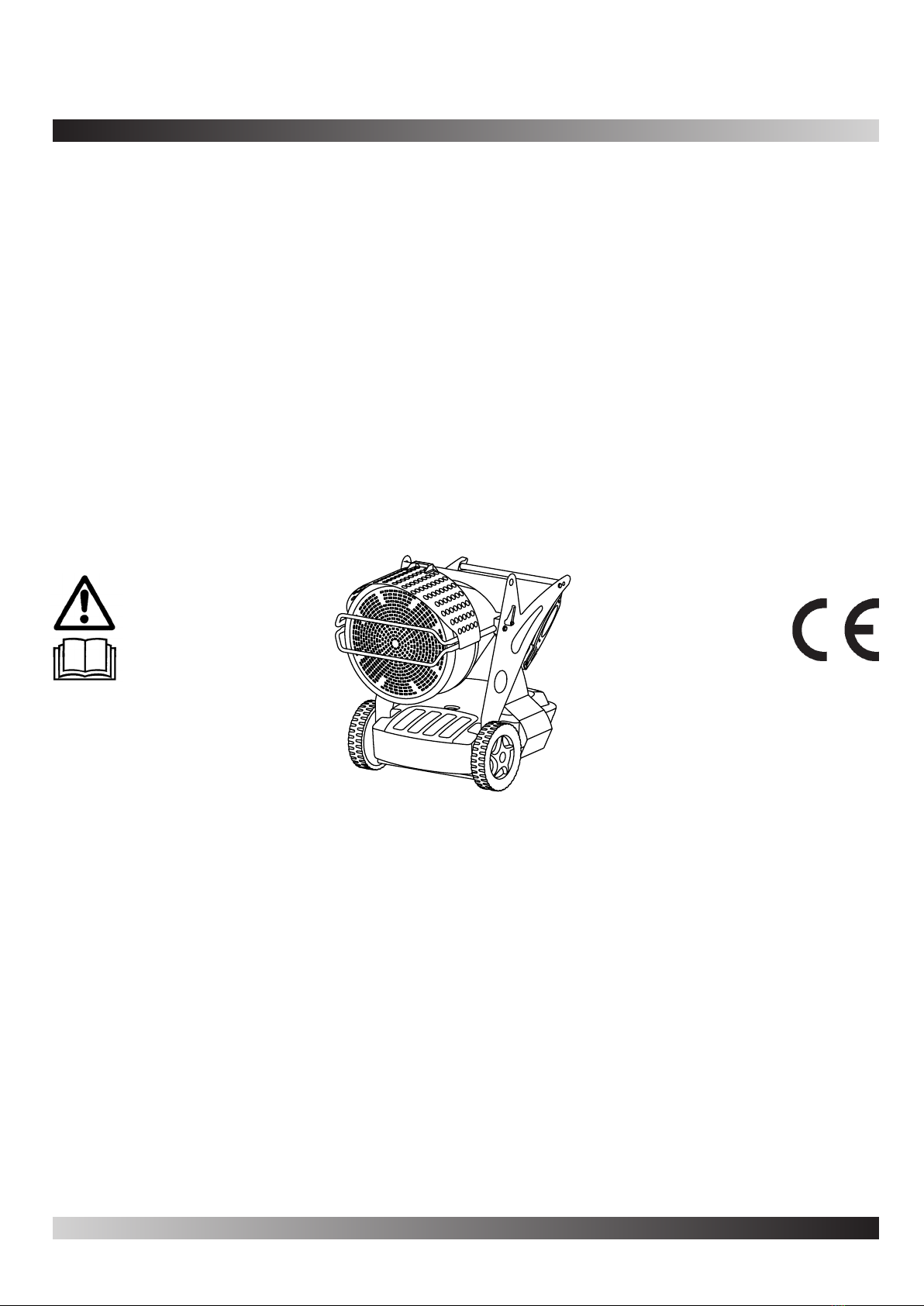
INFORMAZIONI SULLA SICUREZZA
ATTENZIONE
IMPORTANTE: Leggere attentamente e completamente il
manuale d’istruzioni prima di mettere in funzione o effet-
tuare la manutenzione di questo generatore. L’uso errato
del generatore può causare lesioni gravi o fatali a segui-
to di ustioni, incendio, esplosione, scariche elettriche o
asssia da ossido di carbonio.
PERICOLO: L’asssia da ossido di carbonio può risultare
fatale.
Asssia da ossido di carbonio
cefalee, capogiri e/o nausea. Tali sintomi potrebbero essere
causati dal funzionamento difettoso del generatore. In tal caso
uscire immediatamente all’aperto. Far riparare il generatore.
Accertarsi di leggere e comprendere tutte le avvertenze.
Conservare questo manuale a titolo di futuro riferimento: funge
infatti da guida al funzionamento sicuro e corretto del generatore.
incendio o di esplosione. Non fare mai uso di benzina, nafta,
-
mabili.
Rifornimento:
-
cato ed avere totale dimestichezza con le istruzioni del fab-
bricante e con la normativa vigente in merito al rifornimento
sicuro dei generatori.
b) Usare solamente il tipo di combustibile espressamente speci-Usare solamente il tipo di combustibile espressamente speci-
c)
ed attendere che il generatore si raffreddi.
d) Nel corso del rifornimento, ispezionare tutte le linee del com-Nel corso del rifornimento, ispezionare tutte le linee del com-
bustibile ed i relativi raccordi, alla ricerca di eventuali perdite.
Qualsiasi perdita va riparata prima di rimettere in funzione il
generatore.
-
cio, in vicinanza del riscaldatore, una quantità di combustibile
superiore a quella necessaria per mantenere in funzione il
riscaldatore per una giornata. Le cisterne di magazzinaggio
del carburante devono trovarsi in una struttura separata.
f) Tutti i serbatoi del combustibile devono trovarsi ad una di-
stanza minima di sicurezza (secondo la normativa vigente)
da riscaldatori, cannelli ossidrici, attrezzature per la saldatura
e simili fonti di accensione (ad eccezione del serbatoio del
combustibile incorporato nel generatore).
g) Il combustibile va conservato in locali il cui pavimento non
permetta la penetrazione ed il gocciolio del combustibile su
h) La conservazione del combustibile va effettuata in conformità
alla normativa vigente.
elevate concentrazioni di polvere.
locali ed alla normativa vigente.
di copertura simili devono essere situati a distanza di sicurezza
da essi. La distanza minima di sicurezza consigliata è quella
consigliata dalle normative vigenti nello stato di appartenenza.
Si consiglia anche di usare materiali di copertura di tipo igni-
che prendano fuoco e prevenire interferenze con il generatore
causate dal vento.
Usare solamente in aree ben ventilate. Predisporre pertanto
un’apertura o comunque un ricambio d’aria adeguato secondo
le normative vigenti nello stato di appartenenza allo scopo di
immettere aria fresca dall’esterno.
Alimentare il generatore solamente con corrente avente la ten-
a massa.
Mantenere una distanza minima di sicurezza tra il riscaldatore
e sostanze combustibili secondo le normative vigenti nello
stato di appartenenza.
e livellata, in modo da evitare i rischi di incendio.
Quando si sposta o si conserva il generatore, mantenerlo in
posizione livellata, per evitare la fuoriuscita del combustibile.
Tenere lontani i bambini e gli animali dal generatore.
Scollegare il generatore dalla presa di rete quando non lo si
usa.
Quando è controllato da un dispositivo di controllo (termostato
ambiente), il riscaldatore può accendersi in qualsiasi momen-
to.
Non usare mai il generatore in stanze frequentemente abita-
te.
Non ostruire mai le griglie di aspirazione o di dissipazione.
Quando il riscaldatore è caldo, collegato alla rete o in funzione
non deve mai essere spostato, maneggiato, rifornito né sog-
getto ad alcun intervento di manutenzione.
Il fumo che fuoriesce dalla prima combustione è dovuto al-
l’evaporazione di materiale organico (ceramiche) presente
nella camera di combustione e da olio anticorrosione presente
minuto il fumo sparirà.
Utilizzare la macchina all’interno di una temperatura ambiente
2
it

3
it
IDENTIFICAZIONE DEI PRODOTTI
A. Camera di combustione, B. Foro sollevamento apparecchio,
C.D. Mandata
combustibile, E. Ritorno combustibile, F. Tappo carico combu-
stibile, G. Piede o ruota (optional), H. Indicatore livello combu-
stibile, I. Vite bloccaggio gruppo combustione, L.M.
Tappo di scarico del serbatoio, N. Serbatoio combustibile, O.
Maniglie trasporto generatore, P. Perno bloccaggio maniglia, Q.
Bruciatore, R. Maniglione di rotazione della camera combustio-
ne
A.
B.
C.
D.
E.
F.
G.
H.
I.
R. Q.
P.
O.
N.
M.
L.
A.
B.
C.
D. E.
G.
H.
F.
R.
I. D. L. M. N1. O1.
Q.
T.
S.
P.
U1.
U2.
U1.
N2.
N2.
O2.
A. Regolazione aria, B. Interruttore ON/OFF, C. Interruttore
ON/OFF seconda potenzialità (XL 9SR), D. Pulsante RESET,
E. Spia tensione, F. Cofano bruciatore, G. Spina per termosta-
to ambiente, H.I. Apparecchiatura di
post-ventilazione, L. M.
Trasformatore, N1. Regolazione pressione della pompa (XL
9ER), N2. Regolazione pressione della pompa (XL 9SR), O1.
Pompa combustibile (XL 9ER), O2. Pompa combustibile (XL
9SR), P.Condensatore, Q. Motore, R. Canotto bruciatore, S.
Regolazione testa di combustione, T. Fotoresistenza, U1. Elet-
U2. Elettrovalvola
Figura 3
Figura 4
Figura 5 - Comandi
Figura 6 - Componenti bruciatore

COMBUSTIBILE
ATTENZIONE: Il generatore funziona SOLO a cherosene
o gasolio.
L’utilizzo di combustibile impuro può causare:
A temperature basse utilizzare additivi antigelo non tossici.
PRINCIPIO DI FUNZIONAMENTO
L’aria necessaria per garantire una corretta combustione viene
prodotta dalla rotazione di una ventola interna al bruciatore. Il
combustibile che viene polverizzato da un ugello ad una elevata
pressione. Il combustibile polverizzato dall’ugello è garantito da
una pompa rotativa che aspira il combustibile dal serbatoio e lo
spinge ad alta pressione sino all’ugello per la polverizzazione.
MESSA IN FUNZIONE
AVVERTENZE: Prima di mettere in funzione il generatore
e, quindi, prima di collegarlo alla rete elettrica di alimen-
tazione si deve controllare che le caratteristiche della rete
elettrica corrispondano a quelle riportate sulla targhetta
identicativa del generatore.
ACCENSIONE DEL GENERATORE
1. Seguire tutte le istruzioni relative alla sicurezza.
2. Riempire il serbatoio di combustibile.
3. Chiudere il tappo del serbatoio.
4. Inserire la spina del cavo di alimentazione in una presa a
muro collegata a massa e avente tensione uguale a quella
ACCENSIONE SENZA TERMOSTATO AMBIENTE
• XL 9ER
Portare l’interruttore (B Fig. 5) nella posizione ON (I). Inizia il
combustione.
• XL 9SR
AVVERTENZA: Prima di accendere il generatore assicu-
rarsi che l’interruttore (C Fig. 5) sia nella posizione .
Portare l’interruttore (B Fig. 5) nella posizione ON Inizia il pe-
combustione.
Per avere la massima potenzialità portare l’interruttore (C Fig. 5)
nella posizione ( ).
ACCENSIONE CON TERMOSTATO AMBIENTE
Regolare il termostato ambiente o il dispositivo di controllo (ad
esempio un timer), se collegato, in modo da consentire il fun-
zionamento.
ATTENZIONE: Il generatore può funzionare in modo
automatico SOLO quando un dispositivo di controllo,
quale ad esempio un Termostato Ambiente o un Timer
e collegato al generatore. Per collegare il dispositivo di
controllo all’apparecchio consultare il paragrafo “SCHE-
MA ELETTRICO”.
Alla prima messa in servizio o dopo lo svuotamento completo
-
atteso per circa un minuto, premere il pulsante di Reset (D Fig.
5 e 6) e riavviare l’apparecchio.
In caso di mancato funzionamento le prime operazioni da fare
sono le seguenti:
1. Controllare che il serbatoio (N Fig. 4) contenga ancora gasolio.
2. Premere il pulsante di riarmo (D Fig. 5 o 6).
Se dopo tali operazioni il generatore non funziona, si deve con-
la causa del mancato funzionamento.
ATTENZIONE: Prima della seconda messa in funzione (a
generatore spento e adeguatamente freddo) assicurare il
serraggio delle viti che bloccano il deettore anteriore (L
Fig. 4)
AVVERTENZA: La linea elettrica di alimentazione del
generatore deve essere provvista di messa a terra e di
interruttore magneto-termico differenziale. La spina
elettrica del generatore deve essere allacciata ad una
presa munita di interruttore di sezionamento.
SPEGNIMENTO GENERATORE
se collegato, sul termostato ambiente o sul dispositivo di con-
-
post-ventilazione (raffreddamento).
AVVERTENZA: Prima di staccare il cavo di alimentazione
dalla presa, attendere il completamento del ciclo di post-
ventilazione (raffreddamento di circa 3 min).
DISPOSITIVI DI SICUREZZA
Il generatore è dotato di un’apparecchiatura di sicurezza (L Fig.
durante il funzionamento, tale apparecchiatura provoca il blocco
del bruciatore e l’accensione della spia del pulsante RESET (D
Fig. 5 o 6).
Il generatore è dotato anche di un’apparecchiatura di post-venti-
lazione. Questa apparecchiatura consente il raffreddamento ot-
timale ed automatico della camera di combustione per un tempo
di circa 3 min.
Prima di rimettere in funzione il generatore si deve individuare
ed eliminare la causa che ha prodotto il blocco.
TRASPORTO E MOVIMENTAZIONE
AVVERTENZA: Prima di sollevare o spostare la macchina
ci si deve assicurare che i tappi del serbatoio (F e H Fig.
3) siano ben chiusi.
TRASPORTO
Il generatore può essere agevolmente spostato da un ambiente
ad un altro, come altresì può essere sollevato e posizionato a
diversi livelli d’impiego, tramite la disposizione si speciali gol-
fari (B Fig. 3 o 7). È possibile pertanto ancorare la macchina
e sollevarla per posizionarla dove è necessario per riscaldare,
scongelare e asciugare.
4
it

5
it
MOVIMENTAZIONE
Il generatore può essere fornito di ruota piroettante (G Fig. 3).
In questo caso, se il terreno lo consente, occorre spingere il
generatore come un carrello. Nel caso l’apparecchio fosse
sprovvisto di ruota piroettante occorre sbloccare il perno (P
Fig. 4) posizionato su uno dei montanti laterali del generatore.
9). Sollevare il generatore e spostarlo facendolo scorrere sulle
ruote anteriori.
AVVERTENZA: Prima di spostare l’apparecchio si deve:
arrestare la macchina secondo le indicazioni descritte
nel paragrafo “SPEGNIMENTO GENERATORE”; disinse-
rire l’alimentazione elettrica scollegando la spina dalla
presa elettrica a muro ed attendere che il generatore si
raffreddi.
PROGRAMMA DI MANUTENZIONE
PREVENTIVA
AVVERTENZA: Prima di iniziare qualsiasi operazione di
manutenzione si deve: arrestare la macchina secondo le
indicazioni descritte nel paragrafo “ARRESTO”; disinse-
rire l’alimentazione elettrica estraendo la spina dalla pre-
sa elettrica ed attendere che il generatore si raffreddi.
Le istruzioni presenti in questo paragrafo, che riguardano i tempi
di manutenzione, sono strettamente connesse alla pulizia del
combustibile e al tipo di ambiente di utilizzo del generatore. In
particolare, le tempistiche sotto riportate si riferiscono ad am-
bienti di lavoro ventilati e poco polverosi nonché all’utilizzo di
combustibile pulito.
-
Smontare il bruciatore e pulire all’interno del canotto del bru-
-
PULIZIA FILTRO GASOLIO
(cartuccia).
Pulirlo adeguatamente con cherosene.
-
PULIZIA FILTRO POMPA
pompa del bruciatore (O Fig. 6).
pompa.
A.
B.
C.
D. A. Guarni-
zioni,
B. Bicchiere,
C. Elemento
D.
Corpo in-
gresso/uscita
combustibile
Figura 10 - Filtro
A.
B.
C.
D.
A.
B.
C.
D.
A.-
B. Elettroval-
vola singola
per XL 9ER,
doppia per XL
9SR,
C. Filtro,
D. Corpo
pompa
Figura 11 - Pompa bruciatore
Figura 7 - Golfari di ancoraggio
Figura 8 - Posizione maniglie chiuse
Figura 9 - Posizione maniglie aperte

146
it
PULIZIA DEL BRUCIATORE
Svitare la vite (H Fig. 5) che blocca il bruciatore alla camera di
combustione (A Fig. 3).
Estrarre il bruciatore dalla camera di combustione (vedi Fig. 3).
Svitare le tre viti (B Fig. 12) che bloccano il canotto del
bruciatore (A Fig. 12).
Ruotare il canotto in senso orario guardando il bruciatore e
Svitare l’ugello (G Fig. 14) dal portaugello (F Fig. 14). Pulirlo, o
se necessario, sostituirlo.
Rimontare l’ugello (G Fig. 14) nella sua sede.
-
guatamente le distanze secondo l’immagine (Fig. 14) rappre-
sentativa.
ACCESSORI
TERMOSTATO AMBIENTE
COLLEGAMENTO DEL TERMOSTATO AMBIENTE
AVVERTENZE: Prima di iniziare l’operazione di collega-
mento del dispositivo di controllo si deve: arrestare la
macchina secondo le indicazioni descritte nel paragrafo
“SPEGNIMENTO GENERATORE”; disinserire l’alimenta-
zione elettrica estraendo la spina dalla presa elettrica ed
attendere che il generatore si raffreddi.
FILTRO PRE-RISCALDO COMBUSTIBILE
RUOTA GIREVOLE CON FRENO
A. C.
B.
Figura 12 - Smontaggio canotto-bruciatore
C.
H.
D.
4 mm
4 mm
6-7 mm
E.
F.
G.
22 mm
Figura 13 - Smontaggio gruppo disco amma-elettrodi
Figura 14 - Distanze elettrodi ugello
A. Canotto, B. Vite canotto, C. D.
E. Elettrodi, F. Portaugello, G. Ugello. H. Vite

7
it
INDIVIDUAZIONE DEI GUASTI
AVVERTENZA: Prima di iniziare qualsiasi operazione di manutenzione si deve: arrestare la macchina secondo le indicazioni
descritte nel paragrafo “SPEGNIMENTO GENERATORE”; disinserire l’alimentazione elettrica estraendo la spina dalla presa
elettrica ed attendere che il generatore si raffreddi.
GUASTO POSSIBILE CAUSA SOLUZIONE
L’apparecchio va in bloc-
Pulsante di RESET (D
Fig. 5 o D Fig. 6) acceso
1. Circuito della fotoresistenza guasto o fotoresi-fotoresistenza guasto o fotoresi-
stenza sporca di fumo
2. Filtro Combustibile sporco
guasto
1. Pulire o sostituire la fotoresistenza
2.
4. Pulire
L’apparecchio va in bloc-
co spruzzando combus-
Pulsante di RESET (D
Fig. 5 o D Fig. 6) acceso
1. Impianto elettrico non conforme
2. Trasformatore (M Fig. 4) guasto
3. I cavetti del trasformatore di accensione scarica-
no a massa
4. Le punte degli elettrodi non sono alla giusta di-
stanza
5. Gli elettrodi scaricano a massa perchè sporchi o
per isolante danneggiato
2. Sostituire
3. Sostituire
4. Riportarle nella posizione prescritta (vedi Fig.
14)
5. Pulire o se necessario sostituire
L’apparecchio va in
blocco senza spruzzare
combustibile.
Pulsante RESET (D Fig.
5 e 6)
1. Fotoresistenza vede una intensa fonte di luce
2. Manca una fase al motore
3. Combustibile non arriva alla pompa
4. Manca combustibile nel serbatoio
5. Ugello otturato
1. Posizionare la macchina evitando la fonte di
2. Controllare la linea di alimentazione
3. Controllare la tubazione di mandata (D Fig. 3)
4. Effettuare il rifornimento
5. Smontare e pulire o se necessario sostituire
Bruciatore non parte 1. Dispositivo di controllo (termostato ambiente o
timer)
2. Fotoresistenza (T Fig. 6) in corto circuito
3. Manca la tensione per interruttore generale aper-
to o interruttore di massima del contattore scatta-
to o mancanza di tensione nella linea elettrica
4. L’installazione del dispositivo di controllo (termo-
stato ambiente o timer) non è corretta
5. Guasto interno dell’apparecchiatura di controllo
6. Fusibile bruciato
1. Regolare il dispositivo di controllo
2. Sostituire la fotoresistenza
3. Chiudere gli interruttori o attendere il ritorno
della corrente
4. Controllare l’installazione secondo la descri-
5. Sostituirla
6. Aprire il cofano (F Fig. 5) e sostituire
Fiamma non ben
confermata con odore
cattivo, fumo nero e
1. Pressione di polverizzazione bassa
3. Ugello otturato perchè sporco o logoro
4. Acqua nel combustibile. Carburante di cattiva
qualità
5. Il serbatoio sta esaurendo il combustibile
1. Ripristinarla al valore previsto
2. Aumentare l’aria di combustione
3. Pulire o sostituire l’ugello
4. Scaricare il combustibile dall’apposito tappo di
scolo (M Fig. 4)
5. Effettuare il rifornimento di combustibile

1
de
VERZEICHNIS
1. DAS PRODUKT
1. AUSPACKEN UND VERPACKUNG
2. SICHERHEITSINFORMATIONEN
3. PRODUKTBESCHREIBUNG
4. BRENNSTOFF
4. ARBEITSWEISE
4. INBETRIEBNAHME
4. SICHERHEITSVORRICHTUNG
4. TRANSPORT UND BEWEGBARKEIT
5. VORBEUGENDE WARTUNGSVERFAHREN
6. ZUSÄTZLICHES ZUBEHÖR
7. FEHLERSUCHE
DAS PRODUKT
XL9isteinStrahlungswärmegenerator.DieStrahlungstechnologie
verwendet das gleiche physikalische Prinzip, das für die Wärme
des Sonnenlichts verantwortlich ist. Die Sonne erwärmt Körper
nicht durch Warmluftströmung, sondern mit Strahlungswellen.
Das Strahlungssystem ist sehr erfolgreich bei unseren
professionellen Kunden, da diese Technologie sehr viele Vorteile
bietet. XL 9 beruht auf diesem physikalischen Prinzip und ist
somit ein besonderer Wärmegenerator, der dort eingesetzt
wird, wo eine gleichmäßige, homogene Wärmequelle benötig
wird, die wärmt, auftaut und trocknet. Darüber hinaus kann man
dank seiner Geräuschlosigkeit bei eingeschaltetem Generator
arbeiten, ohne durch den normalerweise von diesen Maschinen
verursachten Lärm gestört zu werden. Der Generator ist mit
Reifen ausgestattet und kann so leicht umgestellt werden,
außerdem kann er auch angehoben und mittels spezieller
Ringschrauben auf unterschiedlichen Höhen genutzt werden.
Seine große Leistungsfähigkeit und die Möglichkeit, ihn durch
Einschalten des Thermostats auf Automatik zu schalten,
gewähren dem Nutzer eine große Einsatzfreiheit. Ein außen
angebrachter Anzeiger erlaubt es zu überprüfen, wie viel
Brennstoff noch im Tank ist und ob es nötig ist, nachzufüllen.
Das Modell SR bietet zwei Potenzstufen und ermöglicht so eine
Einsatz und der Jahreszeit.
AUSPACKEN UND VERPACKUNG
AUSPACKEN
Die zur Verpackung des Gerätes verwendeten Bänder entfer-
nen (Abb. 1).
Die Verpackung an der Oberseite öffnen.
Den Karton von oben her abnehmen.
Die Bänder entfernen, mit denen das Heizgerät an der Palette
befestigt ist (Abb. 2).
Das Gerät vorsichtig von der Palette fahren.
Das Verpackungsmaterial gemäß den gesetzlichen Bestim-
mungen entsorgen.
Das Gerät auf eventuelle Transportschäden überprüfen. Wenn
das Heizgerät beschädigt ist, sofort den Händler benachrichti-
gen, bei dem das Gerät erworben wurde.
VERPACKUNG UND LAGERUNG
Falls der Generator gelagert werden soll oder große
Transportschäden aufweist oder repariert werden soll, muss:
Kontrolliert werden, dass die Maschine keine Schäden
aufweist, vor allem Verlust von Brennstoff. Sollte dies der Fall
sein, den Tank leeren.
Der Generator auf die gleiche Palette gestellt werden, auf
der er ausgepackt wurde (Lagerung) oder auf eine für die
Rückgabe geeignete Palette (Euro-Pallet EPA).
Der Generator entsprechend an der Palette befestigt werden
(Abb. 2).
Wenn möglich die Kartonverpackung von oben auf der Palette
(Abb. 1).
Stellen das Gerät in geeigneten und nicht naßen Ort. Nicht
mehr als 2 Geräte übereinanderlegen. Schicken das Heizer
als Abbildung Abb. 1 oder wenigstens als Abb. 2.
Abbildung 1 - Verpackung
Abbildung 2 - Auf der palette

2
de
SICHERHEITSINFORMATIONEN
WARNHINWEISE
WICHTIG: Lesen Sie diese Bedienungsanleitung vor der
Inbetriebnahme oder der Wartung dieses Heizgerätes
sorgfältig und vollständig durch. Unsachgemäße Verwen-
dung dieses Heizgerätes kann schwere Verletzungen oder
Tod durch Verbrennung, Feuer, Explosion, Elektroschock
sowie Kohlenmonoxydvergiftung zur Folge haben.
GEFAHR: Eine Kohlenmonoxydvergiftung kann tödlich
sein.
Kohlenmonoxydvergiftung - Die frühen Anzeichen einer Koh-
lenmonoxydvergiftung gleichen denen einer Grippe, wie zum
Beispiel Kopfschmerzen, Schwindel und/oder Übelkeit. Diese
Symptome können durch eine fehlerhafte Funktionsweise Ihres
Heizgerätes bedingt sein. In diesem Fall begeben Sie sich
sofort ins Freie. Lassen Sie Ihr Heizgerät überprüfen und re-
parieren. Gewisse Personen sind anfälliger für Kohlenmonoxyd
als andere: z.B. schwangere Frauen, Personen mit Herz- oder
Vergewissern Sie sich, dass Sie alle Warnhinweise gelesen und
verstanden haben. Bewahren Sie diese Betriebsanleitung zum
Nachschlagen auf. Sie dient Ihnen als Führer für die sichere und
sachgemäße Bedienung dieses Heizgerätes.
Verwenden Sie nur Kerosin oder Dieselkraftstoff, um Feuer-
und Explosionsgefahr zu vermeiden. Auf keinen Fall Benzin,
Naphtha, Farblösungsmittel, Alkohol und andere hochent-
zündliche Brennstoffe verwenden.
a) Das mit dem Auffüllen von Brennstoff beschäftigte Personal
muss geschult werden und mit den Anweisungen des Her-
stellers und den geltenden Vorschriften für das sichere Auffül-
len von Heizgeräten vollkommen vertraut sein.
b) Es darf nur die Art des Brennstoffes verwendet werden, die
auf dem Datenschild des Heizgerätes angegeben ist.
c) Vor dem Auffüllen muss jede Flamme, einschließlich der
-
rät abgekühlt ist.
d) Während des Auffüllens von Brennstoff müssen alle Brenn-
-
sucht werden. Eventuelle undichte Stellen müssen vor er-
neuter Inbetriebnahme des Heizgeräts abgedichtet werden.
e) Unter keinen Umständen darf mehr als der Tagesbedarf an
Brennstoff im gleichen Gebäude, in der Nähe des Heizgerätes,
gelagert werden. Große Brennstoffvorräte müssen außerhalb
des Gebäudes aufbewahrt werden.
f)
von 762 cm zu Heizgeräten, Brennern, Schweißgeräten und
ähnlichen Entzündungsquellen (ausgenommen der im Heiz-
g) Der Brennstoff muss an Orten gelagert werden, an denen die
Bodenbeschaffenheit Ansammlungen von ausgelaufenem
Brennstoff verhindert und Brennstoff nicht durch tiefer gele-
gene Feuerquellen entzündet werden kann.
h) Die Aufbewahrung von Brennstoff hat gemäß den geltenden
Vorschriften zu erfolgen.
Das Heizgerät niemals in der Nähe von Benzin, Farblösungs-
mitteln oder anderen leicht entzündbaren Dämpfen betreiben.
Während der Verwendung dieses Heizgeräts müssen alle ört-
lich dafür geltenden Bestimmungen und Vorschriften beachtet
werden.
Heizgeräte, die in der Nähe von Abdeckplanen, Zeltplane oder
ähnlichen Abdeckungsmaterialien betrieben werden, sind in
einem sicheren Abstand zu diesen Materialien aufzustellen.
Der empfohlene Mindestabstand entspricht dem von den zu-
ständigen Behörden vorgeschriebenen Abstand. Es wird au-
ßerdem empfohlen, feuerfeste Abdeckungsmaterialien zu ver-
wenden. Jene Materialien müssen sicher befestigt sein, um sie
vor Entzündung zu schützen und um zu verhindern, dass sie
das Heizgerät bei Windstößen berühren und umstoßen.
Nur in gut belüfteten Räumen betreiben. Vorzusehen ist eine
Lüftungsöffnung oder zumindest ein angemessener Luftaus-
tausch gemäß den geltenden Vorschriften, um ausreichende
Frischluftzufuhr zu gewährleisten.
Nur an Orten verwenden, an denen keine entzündbaren
Dämpfe bzw. kein hoher Staubgehalt vorhanden ist.
Nur unter der auf dem Datenschild angegebenen Stromspan-
nung und -frequenz betreiben.
Stets ein ordnungsgemäß geerdetes Verlängerungskabel be-
nutzen.
Mindestabstand des Generators zu entzündbaren Stoffen
nach den gesetzlich geltenden Bestimmungen der zuständi-
gen Behörde.
Zur Vermeidung von Feuergefahr muss das heiße oder in Be-
aufgestellt sein.
Das Heizgerät muss in waagerechter Position bewegt und ge-
lagert werden, um das Verschütten von Brennstoff zu vermei-
den.
Kinder und Haustiere vom Heizgerät fernhalten.
Den Stecker aus der Steckdose ziehen, wenn das Heizgerät
nicht in Betrieb ist.
Wenn das Gerät durch eine Kontrollvorrichtung (Umgebungs-
thermostat oder Timer) gesteuert wird, kann sich das Heizge-
rät jederzeit einschalten.
Das Heizgerät niemals in Wohnräumen benutzen.
Niemals den Lufteinlass oder den Luftauslass des Heizgeräts
versperren.
-
schlossene Heizgerät niemals bewegen, bedienen, mit Brenn-
stoff auffüllen oder warten.
Der Rauch, der bei der ersten Verbrennung austritt, wird durch
die Verdunstung von organischem Material (Keramik) im Ver-
der Komponenten des Brenners verursacht. Nach ein paar Mi-
nuten hört der Rauch auf.
benutzen.

3
de
PRODUKTBESCHREIBUNG
A. Verbrennungsraum, B. Öse für Gerätetransport, C. Brenn-
, D. Brennstoff-ein-
gang, E. Brennstoffausgang, F. Tankdeckel, G. Drehbares Rad
(optional), H. Brennstoffanzeige, I. Feststellknopf für Verbren-
nungsaggregat, L. Heizscheibe (Infrarotstrahler), M. Brennstoff-
auslassdeckel, N. Brennstofftank, O. Handgriffe zum Transport,
P. Feststellstifte für Handgriffe, Q. Brenner, R. Neigungsregler
A.
B.
C.
D.
E.
F.
G.
H.
I.
Abbildung 3
R. Q.
P.
O.
N.
M.
L.
Abbildung 4
A.
B.
C.
D. E.
G.
H.
F.
Abbildung 5 - Schaltung
R.
I. D. L. M. N1. O1.
Q.
T.
S.
P.
U1.
U2.
U1.
N2.
N2.
O2.
A. Luftregulierung, B. ON/OFF-Schalter mit Leuchte, C. Schal-
ter für Brennstoffbeheizung (optional) (XL 9SR), D. RESET-
Schalter, E. Spannungskontrollleuchte, F. Brennergehäuse, G.
Anschluss für Umgebungsthermostat, H. Schraube, I. Nachven-
tilationskarte, L. Flammenkontrollautomat, M. Transformator,
N1. Regulierung Druck (XL 9ER) der Pumpe, N2. Regulierung
Druck (XL 9ER) der Pumpe, O1. Kraftstoffpumpe (XL 9ER), O2.
Kraftstoffpumpe (XL 9SR), P. Kondensator, Q. Motor, R. Bren-
nerrohr, S. Regulierung der Luftklappe, T. Fotowiderstand, U1.
Elektrisches Ventil 1. Stufe der Flamme (XL 9ER-S), U2. Elektri-
sches Ventil 2. Stufe der Flamme (XL 9SR)
Abbildung 6 - Brennerkomponenten

BRENNSTOFF
WARNHINWEIS: Heizgerät NUR mit Kerosin oder Diesel-
kraftstoff betreiben.
Der Gebrauch von unreinem Brennstoff führt zu:
Bei niedrigen Temperaturen ist der Zusatz eines ungiftigen
Frostschutzmittels notwendig.
ARBEITSWEISE
Für die für eine korrekte Verbrennung nötige Sauerstoffzufuhr
wird durch die Drehung eines im Brenner angebrachten Flügel-
rads gesorgt. Die Luft tritt aus dem Rohr des Brenners aus und
vermischt sich mit dem Brennstoff, der bei hohem Druck von
einer Düse pulverisiert wird. Der von der Düse pulverisierte
Brennstoff wir von einer rotierenden Pumpe garantiert, die den
Brennstoff aus dem Tank saugt und ihn unter hohem Druck zur
Düse transportiert, wo er pulverisiert wird.
INBETRIEBNAHME
WICHTIG: Vor der Inbetriebnahme und vor dem Anschluss
an das Stromnetz, muss kontrolliert werden, ob die Span-
nung des Stromnetzes mit der auf dem Generator ange-
gebenen Spannung übereinstimmt.
EINSCHALTEN DES HEIZGERÄTS
1. Alle Sicherheitsanweisungen befolgen.
2. Auftanken mit Dieselkraftstoff oder Kerosin.
3. Den Tankdeckel schließen.
4. Das Netzkabel des Heizgeräts an eine standardmäßige
Schutzkontaktsteckdose anschließen. Darauf achten, dass
die Spannung des Stromnetzes mit der auf dem Generator
angegebenen Spannung übereinstimmt.
BETRIEB OHNE UMGEBUNGSTHERMOSTAT
•XL 9ER
Den Schalter (B Abb. 5) in Position ON (I) bringen. Die Vorven-
-
brennung.
•XL 9SR
ACHTUNG: Vor die Ausschaltung achten sie das die Taste
(C Abb. 5) in Position ist.
Den Schalter (B Abb. 5) in Position ON (I) bringen. Die
die Verbrennung.
Um die maximale Stärke zu erreichen, bringen sie die Taste (C
Abb. 5) in Position ( ).
BETRIEB MIT UMGEBUNGSTHERMOSTAT
Den Umgebungsthermostat oder, falls angeschlossen, die Kon-
trollvorrichtung (zum Beispiel ein Timer) so einstellen, dass das
Gerät betrieben werden kann.
ACHTUNG: Das Heizgerät kann NUR dann automatisch
betrieben werden, wenn eine Kontrollvorrichtung, zum
Beispiel ein Umgebungsthermostat oder ein Timer, am
Gerät angebracht ist. Um die Kontrollvorrichtung an das
Heizgerät anzuschließen, ziehen Sie bitte den Absatz
„SCHALTPLAN“ zu Rate.
Bei der ersten Inbetriebnahme oder nach der vollständigen Ent-
der Düse unausreichend sein und zum Einschreiten der Sicher-
heitsvorrichtung führen, welche die Flamme kontrolliert (siehe
Heizgerät aus. In diesem Fall warten Sie bitte etwa eine Minute,
drücken dann den RESET-Knopf (D Abb. 5 or 6) und schalten
den Apparat erneut ein.
Im Falle ausbleibenden Betriebes, sind zunächst folgende
Schritte durchzuführen:
1. Überprüfen Sie, ob sich noch Brennstoff im Tank (N Abb. 4)
2. Den RESET-Knopf (D Abb. 5 or 6) drücken.
Wenn danach das Heizgerät nach wie vor nicht funktioniert, le-
ACHTUNG: Vor die zweite Zündung (Gerät ausgeschaltet
und ausreichend kühl) versichern sie die Schrauben die
das vorhergehende Umlenkblech (L Abb. 4) blockieren.
WARNHINWEIS: Das Netzkabel des Apparates muss ge-
erdet und mit einem thermomagnetisch differenzierten
Schalter ausgestattet sein. Der Netzstecker des Heizge-
rätes muss an eine Steckdose mit ON/OFF-Schalter ange-
schlossen sein.
AUSSCHALTEN DES GERÄTES
Den Schalter (B Abb. 5) in Position OFF (O) bringen oder, falls
angeschlossen, das Umgebungsthermostat oder die Kontroll-
vorrichtung (Timer) richtig einstellen. Die Flamme erlischt und
die Ventilation wird fortgesetzt bis die Nachventilation (Abküh-
lung) abgeschlossen ist.
WARNHINWEIS: Das Netzkabel erst dann aus der Steck-
dose ziehen, wenn die Nachventilation (Abkühlung von
ca. 3 min) abgeschlossen ist.
SICHERHEITSVORRICHTUNG
Das Gerät ist mit einer Sicherheitsvorrichtung (L Abb. 6) aus-
gestattet, welche die Flamme kontrolliert. Wenn Unregelmäßig-
keiten während des Betriebes auftreten, bewirkt diese Vorrich-
des RESET-Knopfes (D Abb. 5 und 6).
Der Generator verfügt auch über eine Vorrichtung zur Post-Ven-
tilation. Dieses Systems erlaubt eine optimale und automatische
Abkühlung der Brennkammer über einen Zeitraum von circa drei
Minuten. Vor dem erneuten Einschalten des Gerätes muss die
Ursache des Stopps herausgefunden und beseitigt werden.
TRANSPORT UND BEWEGBARKEIT
ACHTUNG: Bevor der Generator umgestellt oder angeho-
ben wird, muss man sich versichern, dass die Tankdeckel
(F und H Add. 3) gut verschlossen sind.
TRANSPORT
Der Generator kann leicht umgestellt werden, außerdem kann
er auch angehoben und, mittels spezieller Ringschrauben, auf
unterschiedlichen Höhen genutzt werden (B Abb. 3 oder Abb.
7). Man kann ihn also befestigen und anheben, um ihn dort ein-
zusetzen, wo erwärmt, aufgetaut und getrocknet werden soll.
4
de

BEWEGBARKEIT
Das Heizgerät kann mit einem drehbaren Rad (G Abb. 3) verse-
hen sein. In diesem Fall kann das Gerät je nach Bodenbeschaf-
fenheit wie ein Wagen geschoben werden. Wenn das Heizgerät
nicht über ein drehbares Rad verfügt, muss man den Feststell-
stift (P Abb. 4) lösen, der sich seitlich am Rahmen des Gerätes
herunterziehen. Die Griffe drehen und in die „Bewegungspositi-
Vorderrädern schieben.
WARNHINWEIS: Bevor das Heizgerät bewegt wird muss
man: das Gerät gemäß den Anleitungen, beschrieben im
Absatz „AUSSCHALTEN DES GERÄTES“, abstellen. Die
Stromversorgung durch herausziehen des Netzsteckers
unterbrechen und warten bis das Heizgerät abgekühlt ist.
VORBEUGENDE
WARTUNGSVERFAHREN
WARNHINWEIS: Vor dem Beginn jeglicher Wartungsar-
beiten muss man: das Heizgerät gemäß den Anleitungen,
beschrieben im Absatz „AUSSCHALTEN DES GERÄTES“,
abstellen. Die Stromversorgung durch herausziehen des
Netzsteckers unterbrechen und warten bis das Heizgerät
abgekühlt ist.
Die in diesem Paragraphen enthaltenen Anweisungen für die
Wartung hängen direkt von der Sauberkeit des Brennstoffs und
dem Einsatzort des Generators ab. Die unten aufgeführten An-
merkungen beziehen sich auf gut gelüftete Arbeitsräume, die
weitgehend staubfrei sind, und sauberen Brennstoff.
Die Filterkartusche aus der Leitung montieren (siehe „REINI-
GUNG DES BRENNSTOFFILTERS
reinigen.
„SÄUBERN
DES FILTERS DER PUMPE).
Den Brenner abmontieren und im Inneren des Brennerrohrs
die Brennscheibe und Elektroden säubern und, wenn notwen-
dig, deren Abstände regulieren (siehe „REGELMÄSSIGE REI-
NIGUNG DES BRENNERS
REINIGUNG DES BRENNSTOFFFILTERS
-
sche) herausnehmen.
-
setzen und das Plastikgefäß an den festen Teil des Brennstoff-
SÄUBERN SIE DEN FILTER DER PUMPE
Brenners (O. Abb. 6) kennzeichnen.
Filterelement zur Pumpe blockiert.
seines Platzes.
.
Setzen Sie das Filterelement zurück in seinen Platz ein und
schrauben Sie die Nuß zur Pumpe.
5
de
A.
B.
C.
D. A. Dichtun-
gsringe,
B. Plastik-
schale,
C. Filtere-
lement,
D. Körper von
IN/OUT
des
Kraftstoffs
Abbildung 10 - Filter
Abbildung 7 - Haken zwecks anheben
Abbildung 8 - Ruheposition
Abbildung 9 - Bewegungsposition
This manual suits for next models
1
Table of contents
Languages:
Other MCS Master Heater manuals

MCS Master
MCS Master B3 EPB Manual

MCS Master
MCS Master B 130 Manual

MCS Master
MCS Master 2 EPB User manual

MCS Master
MCS Master BLP 17M DC Manual

MCS Master
MCS Master B 2 PTC Manual

MCS Master
MCS Master EKO 3 Manual

MCS Master
MCS Master BLP 17M DC Manual

MCS Master
MCS Master B 18 EPR Manual

MCS Master
MCS Master BV 170DV Manual

MCS Master
MCS Master BV 471S Quick start guide