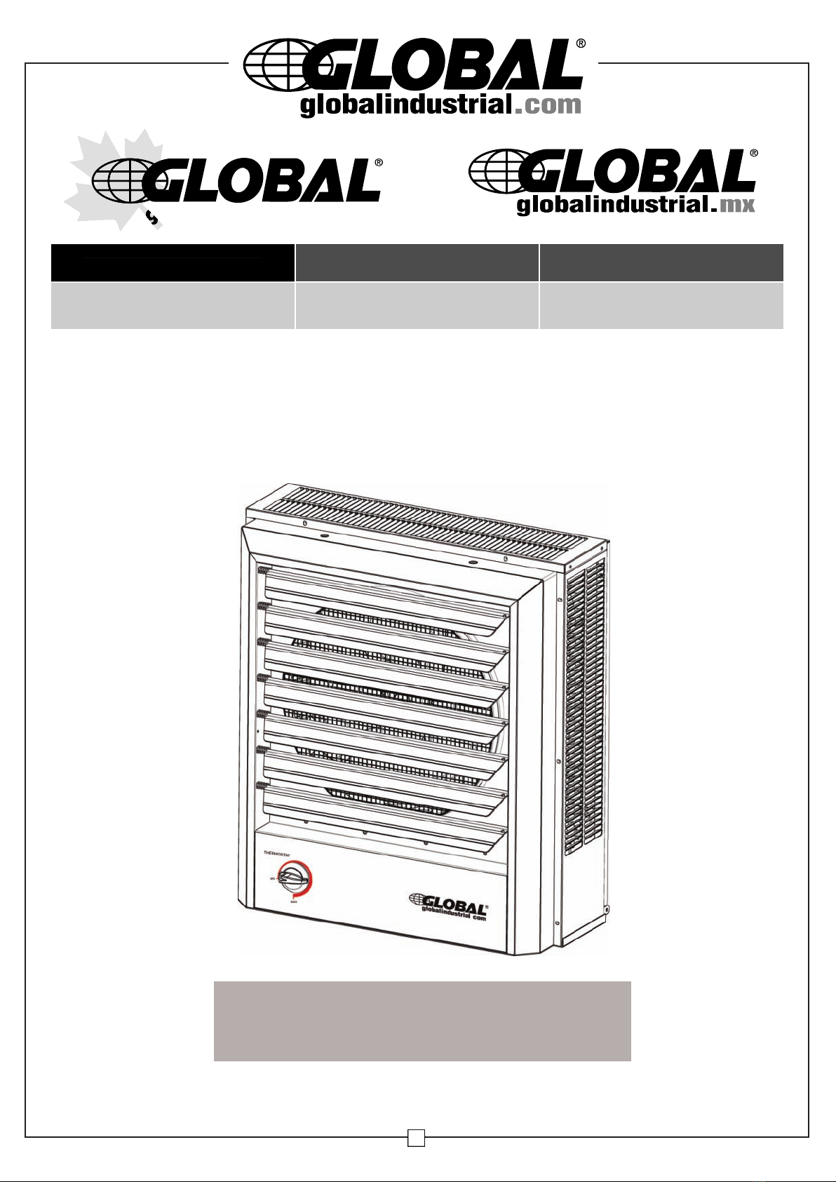
Vertical or Horizontal Downflow Unit Heater User’s Manual
2
IMPORTANT INSTRUCTIONS
When using electrical appliances, basic precautions should
always be followed to reduce risk of fire, electrical shock and
injury to persons or property, including the following:
Please read all instructions before using this heater.
NOTE: This product must be installed by a certified electrician
in accordance with local codes.
Traces of smoke or odor when unit is initiated indicates that small
amounts of oil leaked on heating coil during manufacturing. It will
evaporate quickly and should not re-occur. Make sure the appli-
ance location is well ventilated during operation. It is normal for the
unit to emit sounds when turned on for the first time.
Make sure that the room in which the appliance is located is well
ventilated during this operation.
1.Read all instructions before using this heater.
2.This heater is hot when in use. To avoid burns, do not let
bare skin touch hot surfaces. Keep combustible materials,
such as furniture, pillows, bedding, papers, clothes and
curtains at least 3 ft. (0.9 meters) from the front and top of the
heater and keep them away from the sides and rear.
3.Extreme caution and reasonable supervision is necessary
when any heater is used by or near children, invalids or pets
and whenever the heater is left operating and unattended.
4. Always switch off the heater when not in use.
5. Do not operate any heater after the heater malfunctions, has
been dropped or damaged in any manner. Disconnect power
at service panel and have heater inspected by a qualified
electrician before reusing.
6. Do not use outdoors.
7. To disconnect heater, turn off power to heater circuit at main
disconnect panel.
8.Do not install less than 6 feet (1.8 m) high from the floor.
9.Do not insert or allow foreign objects to enter any ventilation or
exhaust opening as this may cause an electric shock or fire, or
damage the heater.
10.To prevent a possible fire, do not block air intakes or exhaust
in any manner.
11.A heater has hot and arcing or sparking parts inside. To reduce
the risk of fire, do not use it in areas where gasoline, paint, or
flammable vapors and liquids are used or stored.
12.Use this heater only as described in this manual. Any other use
not recommended by the manufacturer may cause fire, electric
shock, or injury to persons.
13. Do not install closer than 1 foot (0.3 m) from both sides and
rear of heater to any adjacent surface/wall.
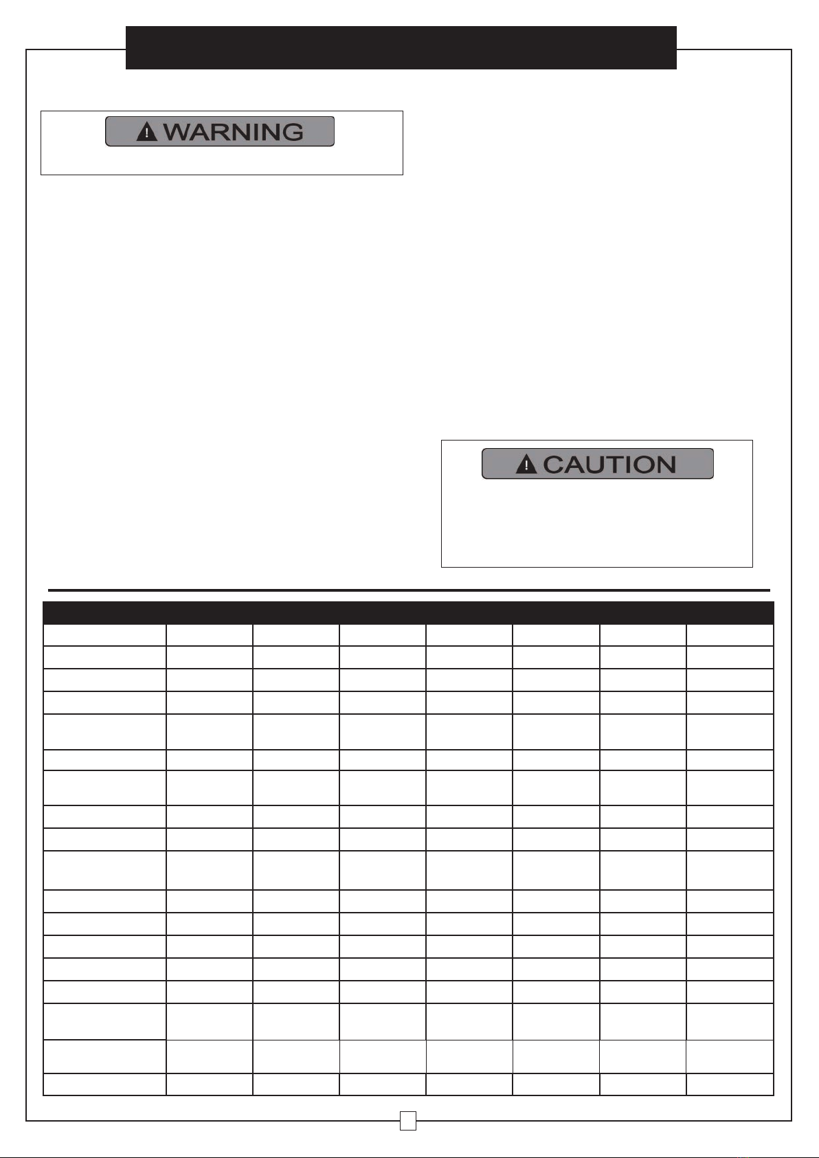
High temperature, risk of fire, keep electrical
cords, drapery, furnishings, and other
combustibles at least 3 feet (0.9 m) from the
front of the heater and away from the side
and rear.
Product Specifications
Model 246725 246132 246104 246133 246103 246134 246727
Length Inches 81/2 81/2 81/2 81/2 81/2 133/4 1313/16
Width Inches 14 19 19 19 19 19 191/4
Height Inches 16 217/16 217/16 217/16 217/16 217/16 211/2
Wire Size For
Installation 14AWG 8AWG 14AWG 6AWG 14AWG 12AWG 10AWG
Net Weight Lbs 28 41 41 41 41 58 64.8
Construction Cold Rolled
Steel
Cold Rolled
Steel
Cold Rolled
Steel
Cold Rolled
Steel
Cold Rolled
Steel
Cold Rolled
Steel
Cold Rolled
Steel
Btu High 17,000 25,600/19,100 25,600 34,100/25,600 34,100 51,200 68,200
Cfm High 350 650 650 650 650 910 1320
Outlet Air Tempera-
ture
150°F @ Ambi-
ent Temp. 77°F
140°F @ Ambi-
ent Temp. 77°F
140°F @ Ambi-
ent Temp. 77°F
149°F @ Ambi-
ent Temp. 77°F
149°F @ Ambi-
ent Temp. 77°F
152°F @ Ambi-
ent Temp. 77°F
160°F @ Ambi-
ent Temp. 77°F
Voltage 480 208/240 480 208/240 480 480 480
Phase 3 1or3 31or3 333
Amps 6 31.3/27 942/36 12 18 24
Watts 5,000 5,600/7,500 7,500 7,500/10,000 10,000 15,000 20,000
Kilowatts 5 5.6/7.5 7.5 7.5/10 10 15 20
Circuit Breaker Amp
rating 20A 40A 15A 55A 15A 25A 30A
Limited Warranty
Years 1111111
Certification UL/cUL UL/cUL UL/cUL UL/cUL UL/cUL UL/cUL UL/cUL