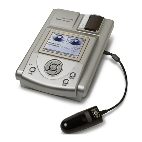
Mcube BioCon-500 User manual

I
User Guide

II

III
CUBESCAN BioCon-500TM
Bladder Volume Measurement System
User Guide
CAUTION: Federal Law restricts this device to sale by or on the
order of a physician.
• Information in this User Guide may change at any time without notice. Examples of
ultrasound images in this User Guide are fictitious and do not in any way represent real
patient data. For up-to-date user information contact your local distributor or
mcube@mcubetech.co.kr.
• Non-Mcube Technology product names may be trademarks or registered trademarks of
their respective owners.
Manufactured by
M ube Te hnology Co., Ltd.
Room#803 Shinnae-Technotown 485
Sangbong-Dong Chungnang-Gu Seoul
Korea 131-220
Tel: +82-2-3421-7780
Fax: +82-2-3421-7076
E-mail: m[email protected]o.kr

IV

V
Table of Contents
1 DEFINITIONS ............................................................................................. 1
2 GENERAL INFORMATION ......................................................................... 2
2.1 INDICATIONS FOR USE ..................................................................................................... 2
2.2 CONTRAINDICATIONS ....................................................................................................... 2
2.3 PRESCRIPTION STATEMENT ............................................................................................. 2
2.4 SAFETY .......................................................................................................................... 3
2.5 SAFE HANDLING PROCEDURES FOR TRANSPORTER ........................................................ 14
2.6 USER INTERFACE ICON DEFINITIONS .............................................................................. 14
3 INTRODUCTION ....................................................................................... 15
3.1 PRODUCT DESCRIPTION ................................................................................................ 15
3.2 SYSTEM COMPONENTS ................................................................................................. 17
3.3 FUNCTIONS OF EACH PART ............................................................................................ 18
4 SETUP ...................................................................................................... 22
4.1 INSTALLING OR REMOVING THE BATTERY ........................................................................ 22
4.2 CHANGING THE THERMAL PAPER ................................................................................... 23
4.3 CHARGING THE BATTERY MODULE OF THE BIOCON-500TM .............................................. 24
4.4 CONNECTING THE PROBE TO THE SYSTEM ..................................................................... 26
4.5 ROLLING CART ASSEMBLY ............................................................................................. 27
5 HOW TO USE ........................................................................................... 38
5.1 QUICK GUIDE ................................................................................................................ 38
5.2 DEVICE CONTROLS AND CONTEXTUAL MENUS ................................................................ 40
5.3 MEASURING URINE VOLUME .......................................................................................... 43
5.4 CHANGING THE PATIENT ID ............................................................................................ 49
5.5 LOADING THE SAVED DATA ............................................................................................ 50
5.6 SETTING THE CLINIC NAME ............................................................................................ 52
5.7 SETTING THE DATE & TIME ............................................................................................ 54
5.8 CUSTOMIZING OTHER SETUP OPTIONS .......................................................................... 55
5.9 CALIBRATING THE BIOCON-500 USING THE CALIBRATION KIT .......................................... 57
5.10 BUTTONS AND THEIR CONTEXTUAL MENU ABBREVIATIONS............................................... 60

VI
5.11 SUMMARY OF EACH SCREEN AND ITS CONTEXT MENUS .................................................. 61
5.12 SUMMARY OF MENUS NOT SHOWN ON CONTEXT MENUS ................................................. 65
6 THE OPTIONAL SOFTWARE(CUBESCANPC) ....................................... 66
6.1 GENERAL INFORMATION ................................................................................................ 66
6.2 INTENDED USE .............................................................................................................. 67
6.3 INSTALLING CUBESCANPC SOFTWARE .......................................................................... 67
6.4 UNINSTALLING SOFTWARE ............................................................................................. 72
6.5 DEVICE DESCRIPTION.................................................................................................... 74
6.6 GETTING STARTED ........................................................................................................ 74
6.7 USE OF THE SOFTWARE ................................................................................................ 76
6.8 SETTING UP CUBESCANPC ........................................................................................... 81
7 TROUBLESHOOTING .............................................................................. 82
7.1 TROUBLESHOOTING ...................................................................................................... 82
8 MAINTENANCE ........................................................................................ 83
8.1 BATTERY CARE ............................................................................................................. 83
8.2 CHANGING THE BATTERY MODULES ............................................................................... 83
8.3 CHANGING THE THERMAL PAPER ................................................................................... 83
8.4 CLEANING & DISINFECTION ............................................................................................ 83
8.5 WEEKLY INSPECTION ..................................................................................................... 84
8.6 DEVICE REPAIR ............................................................................................................. 85
8.7 DISPOSAL ..................................................................................................................... 85
9 SPECIFICATIONS .................................................................................... 86
9.1 SYMBOL DIRECTORY ..................................................................................................... 86
9.2 ACOUSTIC OUTPUT TABLE ............................................................................................. 87
9.3 DEFINITIONS AND SYMBOLS ........................................................................................... 89
9.4 SPECIFICATION OF COMPONENTS................................................................................... 94
10 ENVIRONMENTAL CONDITIONS ............................................................ 96
10.1 BIOCON-500TM ............................................................................................................. 96
10.2 BATTERY MODULE ........................................................................................................ 97
11 GLOSSARY .............................................................................................. 98
12 REFERENCES .......................................................................................... 99

1
1 DEFINITIONS
These definitions are used in this user guide.
WARNING: Describes precautions necessary to prevent injury or loss of life.
CAUTION: Describes precautions necessary to protect the products.
IMPORTANT:
Describes information that a user should know for safe and
effective use of this system.
SCAN : Tactile switch
SCAN : Context menu based on system state (Screen)

2
2 GENERAL INFORMATION
2.1 Indi ations for Use
The BioCon-500TM is a B-mode pulsed-echo ultrasound device. The BioCon-
500TM is intended as a portable battery-operated device. The BioCon-500TM
projects ultrasonic energy through the abdomen of the patient obtaining images
of the bladder in order to calculate the urine volume non-invasively. The
BioCon-500TM is intended to be used only by qualified medical professionals.
Contraindications for the BioCon-500TM are fetal use and use on pregnant
patients.
2.2 Contraindi ations
Do not use the BioCon-500TM on following cases:
a) Fetal use or pregnant patients.
b) Patients with ascites.
c) Patients with open or damaged skin.
d) Wounds in the suprapubic region.
2.3 Pres ription Statement
Caution: Federal Law restricts this device to sale by or on the order of a
physician.

3
2.4 Safety
This guide covers components function maintenance storage and precautions
needed to use this system. All users must read and thoroughly understand this
entire guide prior to using the BioCon-500TM. This section has information on safe
use of the BioCon-500TM (Electrical Safety Battery Safety EMC (Electromagnetic
Compatibility) Equipment Safety).
WARNING:
Risk of explosion:
To avoid the risk of injury do not operate the device in the
presence of flammable gasses or anesthetics. The hazard
of potential explosion exists.
2.4.1 Ele tri al Safety
This device meets IEC 60601-1 ClassⅠ Type BF isolated patient-applied parts
safety requirements. This device complies with the applicable medical equipment
requirements published in the Canadian Standards Association (CSA) European
Harmonized Standards and Underwriters Laboratories(UL) safety standards.
Please review and follow the following safety warnings.
WARNING:
The power supply should be properly grounded. The power
supply must be connected to an AC socket that is medical
grade or equivalent. The grounding pin must not be
removed or tampered with.
Do not use the device if the power cord is damaged.
Do not open the device’s enclosures. All servicing except
battery and printer paper replacement must be made by a
qualified technician.
Inspect the transducer and cable prior to using the device.
Do not use if the transducer or cable is damaged.
Use the device within operating conditions specified in
chapter 10 “Environmental conditions.”
Do not use the device with any defibrillator at the same
time.
Use accessories only recommended by Mcube Technology.
Do not use if the transducer that has been immersed
beyond the specified cleaning or disinfection level.

4
WARNING: The device should be used with ultrasonic gel either applied
on the probe or patient’s abdomen. Thus users should
avoid using this device on patients with skin disease or
injury.
Power Cord:
Make sure the power cord is the correct type for your area.
The equipment has a universal power adapter that allows
operation at either 100-120V AC or at 200-240V AC without
the need for user adjustment.
Always use a hospital grade power cord with the correct
plug type. The cord must be rated for 125VAC at 15A and
be of type SJT or better.
Adapter:
The device complies to the above standards only when
used with the power cord included.. Only use adapters
supplied by Mcube Technology. (see chapter 9.4
Specification of adapter ).
Computer onne tion:
When connecting the BioCon-500TM to a computer the
computer must be certified to EN/IEC/CSA/UL 60950 or
60101-1 standard to maintain the device’s compliance to
EN/IEC/CSA/UL 60601-1-1 standard.
Transmission of data:
When transmitting data to or from a computer make sure
that the BioCon-500TM any accessories and the computer
are at least 2 meters or 6.5 feet away from the patient.

5
2.4.2 Battery Safety
BioCon-500TM uses a Lithium-ion battery pack. To ensure safe use of the
battery observe the following warnings and cautions. If there are any problems
with the battery module immediately discontinue use of the battery and contact
Mcube Technology or your local distributor.
WARNING:
The battery module has built in safety mechanisms. Do not
disassemble or tamper with the battery pack.
Only use the charger that is
supplied with the Unit.
Contact Mcube Technology or your local distributor for
replacements. Do not charge the battery outside of the
recommended conditions as it may damage the battery
resulting in possible leakage of the electrolyte or explosion
(see chapter 9.4 Specification of adapter ). Charge the
batteries only when the ambient temperature is between
+10℃ and +40℃ (+50 - +104℉)(in door use).
Do not short-circuit the battery. Short circuiting the battery
may cause rapid heating resulting is possible explosion
.
To avoid short-circuiting do not let the battery come in
contact with metal objects at any time especially when
transporting.
Only use the manufacturer’s recommended battery.
Do not connect the battery in reverse polarity. Do not
charge the battery in reverse polarity as it may cause the
battery to rapidly heat swell or even explode.
Do not use a battery pack when something appears
abnormal. Such as unusual smell deformation
discoloration etc.
If electrolyte leakage occurs do not touch the liquid. If it
should come into contact with the skin or eyes immediately
seek help from a doctor.
If the battery does vent avoid any contact with the smoke.
Do not expose the battery to water moisture or any type of
liquid.
Do not use or store the battery in temperatures above 60℃

6
WARNING:
or next to any heat source. Doing so can cause the
battery pack to swell and explode.
Do not abuse the battery pack. Doing so can cause
damage to the battery resulting in a potentially unsafe
situation.
CAUTION: When connecting the battery module to a console be
careful about polarity. Be sure to securely fasten the
battery cover.
Long term storage:
If the system is not likely to be used for more than a week
remove the battery module from the device and store it
according to the recommended storage conditions. (See
chapter 10 “Environmental conditions”)
IMPORTANT:
To lengthen lifetime of the battery module it is
recommended to charge up to 75% and to discharge to
20%.
If the battery pack lasts less than 5 minutes after a full
charging replace the battery with a new one.

7
2.4.3 Ele tromagneti ompatibility
The BioCon-500TM has been tested and found to comply with the electromagnetic
compatibility (EMC) limits for medical devices as set forth in IEC 60601-1-2:2001.
These limits are designed to provide reasonable protection against harmful
interference in a typical medical installation.
CAUTION:
To reduce the performance degradation of this device use
medical devices that comply with IEC 60601-1-2 EMC
Standards in the vicinity.
Do not use this device simultaneously with devices having
high EMI levels.
Electrostatic discharge (ESD) is a commonly occurring
phenomenon especially when the humidity is low.
Electrostatic discharge can cause damage to
the
transducer or the system. The following procedures can be
useful in reducing the likelihood of ESD: anti-static spray on
carpets anti-static spray on linoleum and anti-static mats.
2.4.3.1 Manufa turer’s de laration - ele tromagneti emissions
The BioCon-500 is intended for use in the electromagnetic environment specified below.
The customer or the user of the BioCon-500 should assure that it is used in such an
environment.
Immunity test Compliance
Electromagnetic environment -guidance
RF Emissions
CISPR 11
Group 1 The BioCon-500 uses RF energy only for its
internal function. Therefore its RF emissions are
very low and are not likely to cause any
interference in nearby electronic equipment
RF Emissions
CISPR 11
Class A The BioCon-500 is suitable for use in all
establishments other than domestic and those
directly connected to the public low-voltage power
supply network that supplies buildings used for
domestic purposes
Harmonic emissions
Class A

8
IEC 61000-3-2
Voltage fluctuations/
Flicker emissions
IEC 61000-3-3
Complies
2.4.3.2 Manufa turer’s de laration - ele tromagneti immunity
The BioCon-500 is intended for use in the electromagnetic environment specified below.
The customer or the user of the BioCon-500 should assure that it is used in such an
environment.
Immunity test
IEC 60601
Test level
Compliance level
Electromagnetic environment
Electrostatic
discharge (ESD)
IEC 61000-4-2
±6kV Contact
±8kV air
±6kV Contact
±8kV air
Floors should be wood
concrete or ceramic tile. If
floors are covered with
synthetic material the
relative humidity should be at
least 30%.
Electrical fast
transient/burst
IEC 61000-4-4
±2kV for power
supply lines
± 1kV for
input/output lines
±2kV for power
supply lines
± 1kV for
input/output lines
Mains power quality should
be that of a typical
commercial or hospital
environment.
Surge
IEC 61000-4-5
±1kV differential
mode
±2kV common
mode
±1kV differential
mode
±2kV common
mode
Mains power quality should
be that of a typical
commercial or hospital
environment.

9
Voltage dips
short
interruptions and
voltage
variations
on power supply
input lines
IEC 61000-4-11
<5% Uт
(>95% dip in Uт)
for 0.5cycle
40% Uт
(60% dip in Uт )
for 5 cycle
70% Uт
(30% dip in Uт)
for 25 cycle
<5% Uт
(<95% dip in Uт )
for 5 s
<5% Uт
(>95% dip in Uт)
for 0.5cycle
40% Uт
(60% dip in Uт )
for 5 cycle
70% Uт
(30% dip in Uт)
for 25 cycle
<5% Uт
(<95% dip in Uт )
for 5 s
Mains power quality should
be that of a typical
commercial or hospital
environment. If the user of
the BioCon-500 requires
continued operation during
power mains interruptions
it is recommended that the
BioCon-500 ultrasound
system be powered from an
uninterruptible power supply
or a battery.
Power frequency
(50/60Hz)
magnetic field
IEC 61000-4-8
3 A/m 3 A/m Power frequency magnetic
fields should be at levels
characteristic of a typical
location in a typical
commercial or hospital
environment.
NOTE Uт is the a.c. mains voltage prior to application of the test level.
2.4.3.3 Manufa turer’s de laration - ele tromagneti immunity
The BioCon-500 is intended for use in the electromagnetic environment specified below.
Users of the BioCon-500 should ensure that use occurs in such an environment
Immunity test
IEC 60601
test level
Compliance
level
Electromagnetic environment
Conducted
RF
IEC 61000-4-
6
3 Vrms
150 kHz to
80MHz
3 Vrms
150 kHz to
80MHz
Portable and mobile RF communications
equipment should be used no closer to any
part of the BioCon-500 including cables
than the recommended separation distance
calculated from the equation applicable to
the frequency of the transmitter.

10
Radiated RF
IEC 61000-4-
3
3 V/m
80 MHz to
2.5GHz
3 V/m
80MHz to
2.5GHz
Re ommended separation distan e
where P is the maximum output power
rating of the transmitter in watts (W)
according to the transmitter manufacturer
and d is the recommended separation
distance in meters (m).
Field strengths from fixed RF transmitters
as determined by an electromagnetic site
survey a
should be less than the compliance level in
each frequency range. b
Interference may occur in the vicinity of
equipment marked with the following
symbol :
NOTE 1) At 80MHz and 800MHz the higher frequency range applies.
NOTE 2) These guidelines may not apply in all situations. Electromagnetic propagation is
affected by absorption and reflection from structures objects and people.
a Field strengths from fixed transmitters such as base stations for radio (cellular/cordless)
telephones and land mobile radios amateur radio AM and FM radio broadcast and TV
broadcast cannot be predicted theoretically with accuracy. To assess the electromagnetic
environment due to fixed RF transmitters an electromagnetic site survey should be

11
considered. If the measured field strength in the location in which the BioCon-500 is used
exceeds the applicable RF compliance level above the BioCon-500should be observed to
verify normal operation. If abnormal performance is observed additional measures may be
necessary such as re-orienting or relocating the BioCon-500.
b Over the frequency range 150kHz to 80MHz field strengths should be less than [V
1
] V/m.

12
2.4.4 Equipment Safety
To prevent damage to the system and/or accessories observe the following
cautions.
CAUTION:
A dirty transducer can degrade the accuracy of the system.
Clean the transducer with a soft cloth dampened in a mild
soap or detergent.
Dropping a transducer or impact on a transducer can cause
the system to malfunction or be inaccurate. Do not drop
or shock the transducer.
To avoid damaging the cable or transducer connector
handle them with care.
Do not immerse the system or the transducer beyond the
level in specified in 8.4 “Cleaning & Disinfection”
If the system is not likely to be used for more than a week
charge the battery up to about a 75% charge level remove
the battery module from the device and store it according to
storage conditions of the battery. This step will help
maximize the lifetime of the battery. (See chapter 10
“Environmental conditions”)
The device has a setting to power down automatically if not
used during a specified time period. This setting may be
adjusted by selecting the ‘Auto Power’ option in ‘Setup
Menu’.
The device will not power on without a battery installed.
When measuring the urine volume of a patient ensure that
the probe’s SCAN button is on the right side of the patient.
When using the system on a medical cart ensure that the
cart is placed on a flat and level surface.
The safe level of immersion for the probe is marked by the
border between the cap of the probe and the body of the
probe. Do not immerse beyond the ‘B’ portion
of the probe
illustrated in the figure to the left.
Only use the transducer which shipped with your unit
The transducers are not interchangeable between units
They are calibrated to a specific machine. If changing the

13
probe associated with a machine it is necessary to
calibrate the two prior to deployment

14
2.5 Safe Handling Pro edures for Transporter
Quarantine: Packages that are crushed punctured or torn open to reveal
contents should not be placed into deployment. Such packages should be
isolated until the shipper has been contacted provides disposition instructions
and if appropriate arranges to have the product inspected and repacked.
Spoiled Produ t: In the event that damage to packaging results in damage to
the battery causing released electrolyte the spill should be contained and the
shipper should be contacted for instructions.
2.6 User Interfa e I on Definitions
Symbol Meaning
Indicates a male patient
Indicates a female patient
Indicates a battery more than 75% charged
Indicates a battery 50~75% charged
Indicates a battery 25~50% charged
Indicates a battery 5~25% charged
Indicates the battery is near depletion or depleted
Other manuals for BioCon-500
3
Table of contents
Other Mcube Measuring Instrument manuals
Popular Measuring Instrument manuals by other brands

Interacoustics
Interacoustics Callisto Instructions for use

JTS
JTS MONACOR INTERNATIONAL SIEM-111 instruction manual

Sonic Driver
Sonic Driver POCKET PLUS-UFM operating instructions

KROHNE
KROHNE OPTISWIRL 2100 Supplementary instructions

Unico
Unico S-1100 Operation manual

Gems Sensors
Gems Sensors 856 Instruction bulletin