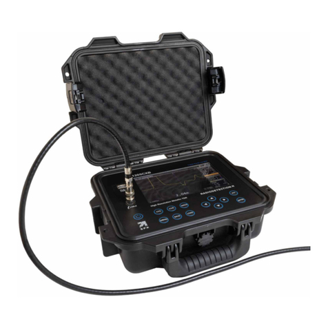
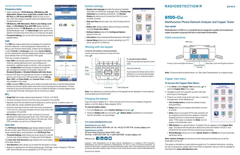
SPX RADIODETECTION 6100 Series User manual

NOTICE
Important Safety Instructions for the 6100 Series
Note: Before you start working with your 6100 device, you need to first read the important safety information provided in
this notice. This document provides information that may supplement or add safety information to the user guide of your
product. Keep this information close at hand. You can obtain a copy of the complete user guide for your product at the
following link: www.radiodetection.com.
Note: The 6100 enclosure may become warm during normal use.
Introducing the 6100 Series
The 6100 is a handheld device designed for installing and activating multiplay services over copper/G.fast/ADSL2+/VDSL2,
and Ethernet, between the service provider and the subscriber premises. It veries that the customer’s modem/router,
equipment and inside wiring are operating correctly. The unit also veries the location of faults during the installation and
repair of voice and DSL circuits.
Typical applications
lAutomatic Pair Quality Test toward remote test head or
far end device (FED)
lMultimeter tests
lNoise tests including power inuence and PSD
lFrequency tests including balance, load coils, and
tracing tone
lFault location tests including TDR and RFL
lSmartR™features including Pair Detective and
FaultMapper
lSupports vectoring and G.INP for operators looking to
mitigate self-FEXT (far end crosstalk) and promote DSL
stability
lADSL2+, VDSL2, and G.fast testing
lOptional ADSL2+ and VDSL2 bonding support
lSupports Ping, FTP, and Traceroute tests with optional
support for Web Browser, VoIP testing, and IPTV
analysis
lEthernet testing for qualifying FTTx service at the
customer premises
lCongurable pass/fail results for automated testing
lProves IPv4 and IPv6 data ow between the network
and the end equipment
Using the 6100
If the equipment is used in a manner not specied by the
manufacturer, the protection provided by the equipment
may be impaired. The 6100 is equipped with a series of
interfaces shown in the following views:
Front
Touchscreen
Power LED
SpeakerBattery LED

Rear
Left side
Battery door
Stylus
Screws Screws
Head Set Jack (2.5mm)
SD Card Port (not used)
USB Host Port
USB Client Port Door
Right side
Door
USB Client Port
DC Power
Stylus
Cable Connections
The graphics below show the connections on the 6100
products.
Ethernet / 1GigE LAN port*
Ground
Terminal
Secondary Tip/A and
Ring/B connectors for DSL
and 4-wire copper testing
Ethernet / 1GigE WAN port
DSL port*
Primary Tip/A and Ring/B
connectors for DSL and
copper testing
Secondary Tip/A wire of phone line
Secondary Ring/B wire
of phone line
Shield of phone line
Primary Tip/A wire of
phone line
Primary Ring/B wire of phone line
WARNING
lA 50 to 500 Vcc limited power source may be present
on connector T/R/G (A/B/E), T1/R1/G (A1/B1/E) when
the unit is testing isolation resistance. Use with caution.
lThese connections are intended for the express
purpose of electrical testing of common telephone line
conductors, within the ranges specied in the Technical
Specications found on the Radiodetection web site.
The device is not intended to be used on telephone
lines having voltages greater than 280 VAC or 400
VDC, and it is also not intended to be used on power
distribution circuits.
CAUTION
The unit is protected against damage caused by fault
voltages that may be present on lines under test. Do not
connect the unit if the maximum expected fault voltage is
greater than 500 volts.
Note: In the 6100-Gfast-Bond model, to test an
ADSL1/2/2+ Annex B interface, the 6100 uses the second
pair (pins 2-5) in the DSL WAN RJ11 connector. When
connecting the unit to a wall socket with a modem cable
that uses the first pair (pins 3-4), use the red cable (pair 2)
of the provided ACC-BD-RJ test cable, RJ14 to dual RJ-11,
and an RJ11 female adapter ACC-RJ11-ADPTR.
*6100-Gfast models only

Getting started with the 6100 Series
Turning the Unit On/O
When you turn the unit on, you may use it immediately
under normal conditions.
To turn the unit on:
Press to start. The unit initializes for a few seconds
and displays the Home pane.
There are two ways to turn o the 6100:
lSuspend: the next time you turn your unit on, you will
quickly return to your work environment.
lShutdown: completely cuts power to the unit; the unit
will perform a complete restart routine the next time
you use it. You should perform a shutdown if you do not
intend to use your unit for a few hours or more.
To enter suspend mode:
Press for about 2 seconds. The 6100 will stay in
suspend mode for 2 hours, after which it will automatically
shut down. This prevents complete battery discharge and
ensures maximum battery performance.
To perform a shutdown:
Hold down for about 4 seconds. The shutdown
process starts.
Note: In both previous cases, if the power adapter is
connected, the 6100 will go through either a fake suspend
or fake shutdown in order to facilitate charging.
Using Menus and Keypad
You can access various tools from the keypad or
menu. Menu options may dier depending on your unit
conguration.
The Home menu is where you can access Copper Test,
DSL/IP Tests, System Settings and Wi-Fi Test (6100-Gfast
models only). Each test has a sub menu.
lTo navigate through the items, use the arrow keys.
lTo conrm a choice or enter a menu, press .
lTo cancel an action or return to the previous item or
pane, press .
lTo return to the home pane, press .
lPresss once to return to the Main test menu or
twice to return to the Home pane.
Note: Pressing while a test is running will also stop the
test and return to the main menu screen.
Note: You can also select an option directly by pressing
the function keys corresponding to the on-screen buttons
at the bottom of the screen. Alternatively, any reference
to pushing buttons on the keypad can be replaced in most
cases by clicking/tapping the touchscreen.
Keypad
Arrow keys
Back
Enter
Power
On-board Help
On-board help is available at any time. Most test operations
pause while you view help, but will resume automatically
when you exit help.
To access help about the current function at any time:
Press and hold the key.
Safety Information
WARNING
You can access various tools from the keypad or menu. Menu
options may dier depending on your unit conguration.
lThe use of controls, adjustments and procedures,
namely for operation and maintenance, other than
those specied herein may result in hazardous radiation
exposure or impair the protection provided by this unit.
lIf the equipment is used in a manner not specied
by the manufacturer, the protection provided by the
equipment may be impaired.
lUse only accessories (such as the car outlet adapter
and batteries) designed for your unit and approved
by Radiodetection. The car outlet adapter contains a
replaceable fuse. Replace the damaged fuse ONLY
with a fuse of the same type: 3AG, UL/CE certied or
equivalent, 16 VDC, 5 A, with an I
2
t between 40 A2s
and 80 A2s. For a complete list of accessories available
for your unit, refer to its technical specications.
lUse only the listed and certied AC adapter provided
by Radiodetection with your unit. It provides reinforced
insulation between primary and secondary, and is
suitably rated for the country where the unit is sold.
Function keys
Home / Help
Start / Stop test

IMPORTANT
lWhen you see the symbol on your unit, make
sure that you refer to the instructions provided in your
user documentation. Ensure that you understand and
meet the required conditions before using your product.
lOther safety instructions relevant for your product are
located throughout this documentation, depending
on the action to perform. Make sure you read them
carefully when they apply to your situation.
Electrical Safety Information
WARNING
The AC adapter/charger provided with this unit (18 W/9 V)
is specically designed to work with your 6100.
lIf you need to ensure that the unit is completely turned
o, disconnect the power cable and remove the batteries.
For more information on how to remove the batteries, see
the section below about replacing the batteries.
lDo not throw batteries into re or water and do not short-
circuit the battery electrical contacts. Do not disassemble.
lRISK OF EXPLOSION IF BATTERY IS REPLACED BY
AN INCORRECT TYPE.
lUse only the certied power cord that is suitably rated
for the country where the unit is used.
lOn the AC/DC adapter, replacing detachable mains
supply cords with inadequately rated cords, may result
in overheating of the cord and create a re risk.
lNever connect the unit to the AC mains when it is used
outdoors.
lOperation of any electrical instrument around ammable
gases or fumes constitutes a major safety hazard.
lTo avoid electrical shock, do not operate the unit if
any part of the outer surface (covers, panels, etc.) is
damaged.
lOnly authorized personnel should carry out
adjustments, maintenance, or repair of opened units
under voltage. A person qualied in rst aid must also
be present. Do not replace any components while the
power cable and batteries are connected.
lUnless otherwise specied, all interfaces are intended
for connection to Safety Extra Low Voltage (SELV)
circuits only.
lUse only the listed and certied AC adapter/charger
provided by Radiodetection with your 6100 unit. It
provides reinforced insulation between primary and
secondary, and is suitably rated for the country where
the unit is sold.
lWhen you use the unit outdoors, ensure that it
is protected from liquids, dust, direct sunlight,
precipitation, and full wind pressure.
CAUTION
lWhen using the 6100 while connected to the AC/DC
adapter/charger, make sure you do not position the
equipment so that it is dicult to disconnect the adapter/
charger from the AC mains.
lYour unit uses smart Lithium Polymer batteries with
built-in protection that have been especially designed
for Radiodetection. For this reason, they can only be
replaced with batteries of the same type and model.
The use of other batteries may damage your unit and
compromise your safety
IMPORTANT
Recycle or dispose of used batteries properly, in
accordance with local regulations. Do not dispose of them
in ordinary garbage receptacles. See your Operation
Manual for more information.
Equipment Ratings
Temperature ranges
Operation
Battery power: 0 °C to 50 °C (32 °F to 122 °F)
AC adapter power: 0 °C to 40 °C (32 °F to 104 °F)
Storage - 40 °C to 70 °C (- 40 °F to 158 °F)
Relative humidity a
Unit: ≤ 95 % non-condensing
AC adapter: 0 % to 80 % non-condensing
Maximum operating altitude
Battery power: 3000 m (9840 ft)
AC adapter power: 2000 m (6560 ft)
Pollution degree
Battery power: 3 b
AC adapter power: 2 c
Overvoltage category
Unit: I
AC adapter: II
Input power d
Unit: 9-24 V; 18 W; 1.67 A
AC adapter: 100 - 240 V; 50/60 Hz; 2.0 A
Measurement category
Not rated for measurement categories
II, III or IV
a. Measured in 0 °C to 31 °C (32 °F to 87.8 °F) range,
decreasing linearly to 50 % at 40 °C (104 °F).
b. Equipment is normally protected against exposure to direct
sunlight, precipitation and full wind pressure.
c. For indoor use only.
d. Not exceeding ± 10 % of the nominal voltage.

Other Safety Symbols on Your Unit
One or more of the following symbols may also appear on
the 6100 or its power supply:
Direct current
Alternating current
General Maintenance
Note: For more information on the maintenance of
your 6100 device, refer to the user guide at
www.radiodetection.com.
The 6100 has been designed to be a rugged and
lightweight piece of test equipment. The 6100 LCD display
should only be cleaned using a soft, lint-free cloth and an
anti-static cleaning solution. Ordinary detergents and other
cleaning solutions may cloud or scratch the surface and
should be avoided.
To help ensure long, trouble-free operation:
lKeep the unit free of dust.
lClean the unit casing and front panel with a cloth slightly
dampened with water.
lStore unit at room temperature in a clean and dry area.
Keep the unit out of direct sunlight.
lAvoid high humidity or signicant temperature
uctuations.
lAvoid unnecessary shocks and vibrations.
lIf any liquids are spilled on or into the unit, turn o the
power immediately and let the unit dry completely.
Battery
The 6100 is equipped with a Lithium Polymer battery.
When fully charged, the battery should provide between 3
and 10 hours of power depending on factors such as: type
of tests performed, display backlight level, and connected
accessories.
When the battery level is very low, tests cannot be
performed. Plug in the AC/DC adapter for continued
operation and to recharge the battery.
Note: Using the unit while charging will significantly
reduce the charge speed.
Note: Using the unit while charging can affect the
measurement performance.
Depending on the grounding, AC power voltage level in
your area, and type of charger used, charging the unit may
trigger a high voltage warning buzzer. Unplug the AC/DC
adapter to confirm if the trigger is influenced from the
charger or a real high voltage on the line.
For optimal charging, stop all tests and disconnect the
measurement cables from the line and/or ground to
continue charging the battery using the AC/DC adapter.
WARNING
lRecharge the battery using only the 6100 and with the
battery properly installed in the unit.
lNever open the battery back panel of the 6100 without
reading the Replacing the Battery section below.
Unit Temperature Handling
When the battery temperature reaches ≥ 55 °C, a warning
message will appear. Tests stop automatically when the
battery temperature reaches 60 °C.
Replacing the Battery
Battery replacement should only be done by a qualied
technician with the appropriate tools on an electronic bench
or similar environment.
To replace the battery:
1. Remove all 4 screws of the battery back panel using a
1.5 mm Allen key. Put aside the screws and the panel
keeping the inside foam seal clean.
2. Pull out the old battery using your ngers. Flipping the
unit, battery-side down, will ease removal. Do not use
tools in order to prevent damage to the battery envelope.
Pull out the electrical connector. Put aside the old
battery.
3. Remove the new battery from its package. Keep the
package for future use. Plug in the electrical connector
ensuring the pins are correctly aligned. Place the new
battery in the 6100.
4. Inspect the inside rib around the 6100 battery
compartment to make sure it is free from any debris.
Remove any debris using a dry cloth. Replace the
battery back panel. Replace the 4 screws with a
moderate torque so the foam seal is evenly compressed
without damaging the screws.

Battery (continued)
WARNING
Only use a Radiodetection battery. Batteries from other
suppliers could result in personal injuries and/or serious
damage to the 6100. See Contacting Technical Support for
information on contacting Radiodetection.
Battery Charging and Replacing
Charging the 6100 battery can take up to 5 hours. This
battery was custom made for your unit; replacement
batteries must be ordered from Radiodetection.
Contacting Technical and Sales Support
Visit https://support.radiodetection.com
or call
UK: +44 (0) 117 976 7776
USA/ Ca: +1 (877) 247 3797
Europe: +31 (0) 314 66 47 00 (Benelux)
+49 (0) 28 51 92 37 20 (Germany)
+33 (0) 2 32 89 93 60 (France)
Asia: +852 2110 8160 (Asia Pacic)
+86 (0) 10 8146 3372 (China)
Aus: +61 (0) 2 9707 3222
For detailed information about technical support,
and for a list of other worldwide locations, visit:
www.radiodetection.com.
Certication Information
North America Regulatory Statement
This unit was certied by an agency approved in both
Canada and the United States of America. It has been
evaluated according to applicable North American
approved standards for product safety for use in Canada
and the United States.
Electronic test and measurement equipment is exempt
from FCC part 15, subpart B compliance in the United
States of America and from ICES-003 compliance in
Canada. However, Radiodetection makes reasonable
eorts to ensure compliance to the applicable standards.
The limits set by these standards are designed to provide
reasonable protection against harmful interference when
the equipment is operated in a commercial environment.
This equipment generates, uses, and can radiate radio
frequency energy and, if not installed and used in
accordance with the Operation Manual, may cause harmful
interference to radio communications. Operation of this
equipment in a residential area is likely to cause harmful
interference in which case the user will be required to
correct the interference at his own expense.
Modications not expressly approved by the manufacturer
could void the user’s authority to operate the equipment.
Simplied EU Declaration of Conformity
Where applicable Radiodetection hereby declares that the
radio equipment type “Wideband Data Transmission” is in
compliance with European Directive 2014/53/EU. The full
text of the EU declaration of conformity is available at www.
radiodetection.com.
Recycling Information
This symbol on the product means that you should
recycle or dispose of your product (including electric
and electronic accessories) properly, in accordance with
local regulations. Do not dispose of it in ordinary garbage
receptacles.
See the Operation Manual for complete recycling/ disposal
procedures and contact information.
Copyright © 2020 Radiodetection Ltd. All rights reserved. Radiodetection is a subsidiary of SPX Corporation. Radiodetection and 6100 are trademarks of Radiodetection Ltd.
Due to a policy of continued development, we reserve the right to alter or amend any published specication without notice. This document may not be copied, reproduced,
transmitted, modied or used, in whole or in part, without the prior written consent of Radiodetection Ltd.
90/6100-NOTICE-ENG/01 1079632
Table of contents
Other SPX Measuring Instrument manuals
Popular Measuring Instrument manuals by other brands
PCB Piezotronics
PCB Piezotronics IMI Sensors EX600B14 Installation and operating manual
ASSEMBLAD
ASSEMBLAD INFRAGAS-196 operating manual

BSS Audio
BSS Audio Case Economic Operation manual

TR-Electronic
TR-Electronic LE-200 user manual

Van Walt
Van Walt Aquaread quick start guide

PCB Piezotronics
PCB Piezotronics IMI SENSORS Y687A01 Installation and operating manual
