BOVIE SPECIALIST ELECTROSURGICAL UNIT
1.
Introduction
INTRODUCTION
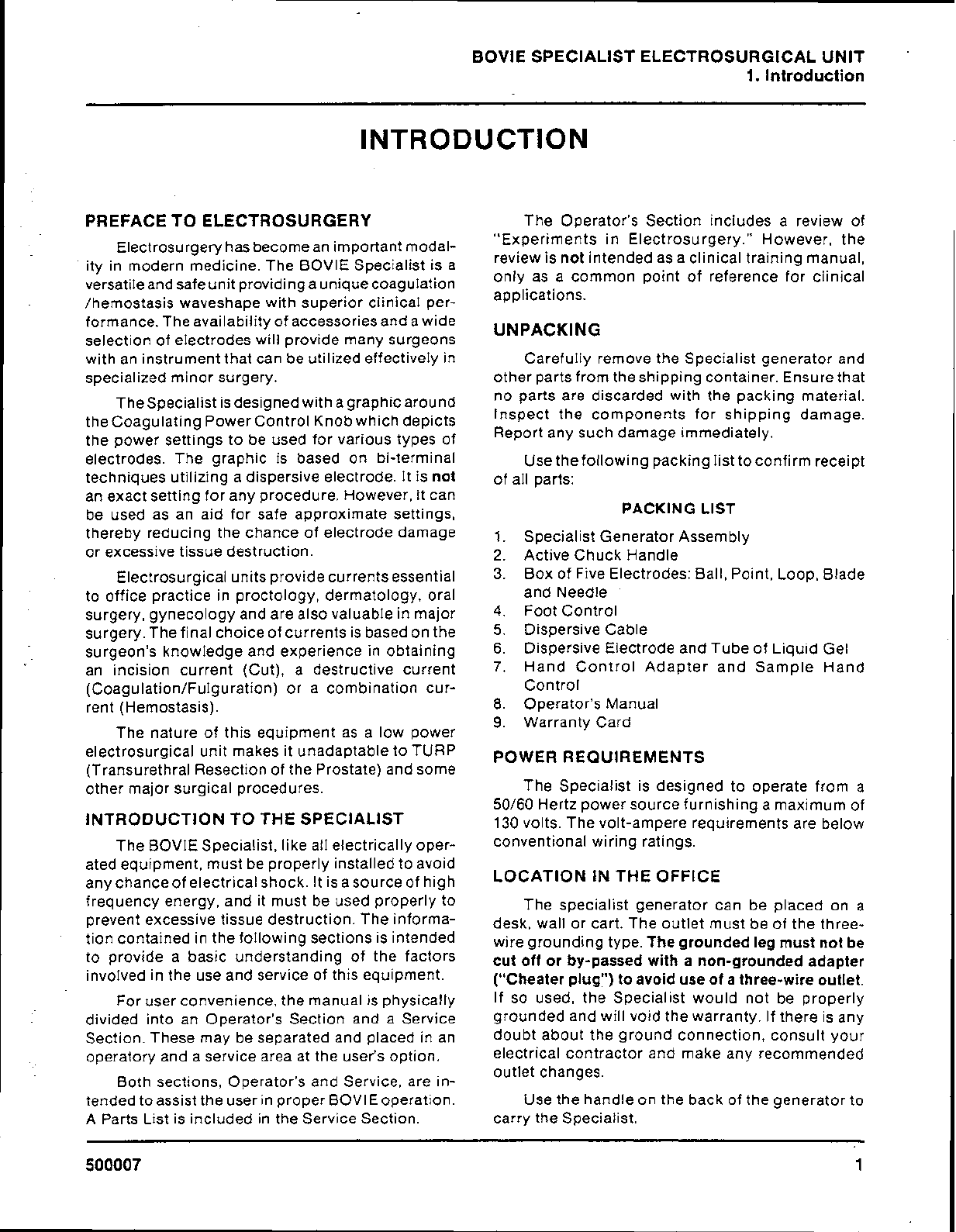
PREFACE TO ELECTROSURGERY
Electrosurgery hasbecomean importantmodal-
ity in modern medicine. The BOVIE Specialist is a
versatileandsafeunitprovidingauniquecoagulation
/hemostasis waveshape with superior clinical per-
formance.Theavailabilityof accessoriesandawide
selection of electrodes will provide many surgeons
with an instrument that can beutilized effectively in
specialized minor surgery.
TheSpecialist isdesignedwithagraphic around
theCoagulatingPowerControlKnobwhich depicts
the power settings to be used for various types of
electrodes. The graphic is based on bi-terminal
techniques utilizing a dispersive electrode. It is
not
an exact setting for any procedure. However, it can
be used as an aid for safe approximate settings,
thereby reducing the chance of electrode damage
or excessive tissue destruction.
Electrosurgical unitsprovidecurrents essential
to office practice in proctology, dermatology, oral
surgery, gynecology andare also valuable inmajor
surgery.Thefinalchoiceof currentsis basedonthe
surgeon's knowledge and experience in obtaining
an incision current (Cut), a destructive current
(Coagulation/Fulguration)
or a combination cur-
rent (Hemostasis).
The nature of this equipment as a low power
The Operator's Section includes a review of
"Experiments in Electrosurgery." However, the
review is
not
intended as aclinical training manual,
only as a common point of reference for clinical
applications.
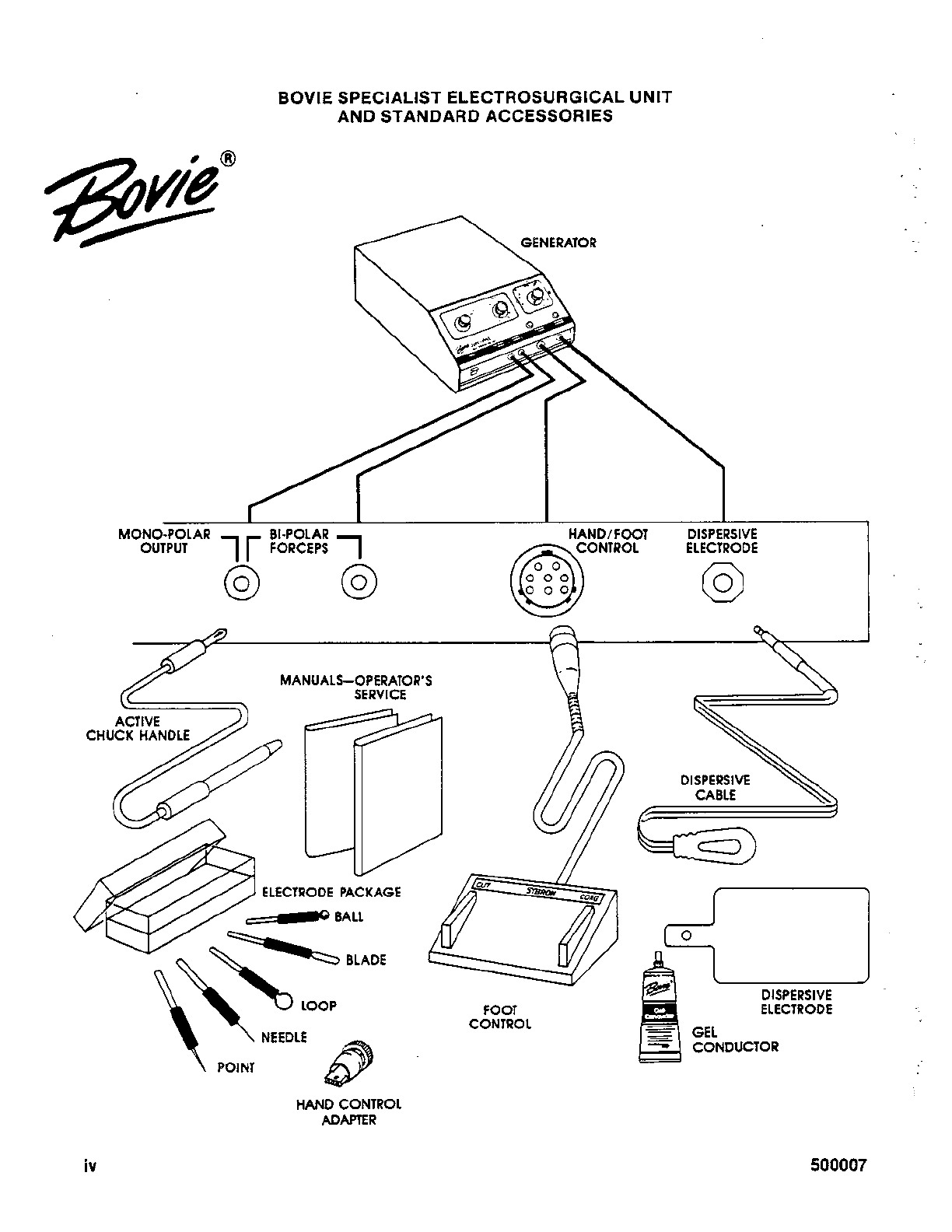
UNPACKING
Carefully remove the Specialist generator and
other partsfromtheshipping container. Ensurethat
no parts are discarded with the packing material.
Inspect the components for shipping damage.
Report any such damage immediately.
Usethefollowingpackinglisttoconfirm receipt
of all parts:
PACKING LIST
1.
Specialist Generator Assembly
2.
Active Chuck Handle
3.
Box of Five Electrodes: Ball,Point,Loop,Blade
and Needle
4.
Foot Control
5. Dispersive Cable
6.
Dispersive Electrode and Tube of Liquid Gel
7.
Hand Control Adapter and Sample Hand
Control
8.
Operator's Manual
9.
Warranty Card
electrosurgical unit makes it unadaptable to TURP
POWER
REQUIREMENTS
(Transurethral Resectionof the Prostate) and some
other major surgical procedures. The Specialist is designed to operate from a
50/60 Hertz power source furnishing amaximum of
INTRODUCTION TO THE SPECIALIST
130 volts. The volt-ampere requirements are below
The BOVIESpecialist, likeall electrically oper- conventional wiring ratings.
atedequipment, must be properly installedto avoid
any chanceof electricalshock. Itis asourceof high
LOCATION INTHE OFFICE
frequency energy, and it must be used properly to
prevent excessive tissue destruction. The informa-
tion contained inthe following sections is intended
to provide a basic understanding of the factors
involved in the use and service of this equipment.
For user convenience,the manual is physically
divided into an Operator's Section and a Service
Section. These may be separated and placed in an
operatory and a service area at the user's option.
Both sections, Operator's and Service, are in-
tendedtoassisttheuser inproperBOVIEoperation.
A Parts List is included in the Service Section.
The specialist generator can be placed
on
a
desk, wall or cart. The outlet must be of the three-
wire grounding type.
The grounded leg must not be
cut off or by-passed with a non-grounded adapter
("Cheater plug") to avoid use of
a
three-wire outlet.
If so used, the Specialist would not be properly
grounded andwill void the warranty. If there is any
doubt about the ground connection, consult your
electrical contractor and make any recommended
outlet changes.
Usethe handleon the back of the generator to
carry the Specialist.