Meanwell PHP-3500-HV User manual

PHP-3500-HV
User's Manual

0. Safety Guidelines
1. Introduction
2. Mechanical Specification and Input/Output Terminals
1.1 Introduction
1.3 Order Information
1.4 Main Specification
1.2 Features
..........................................................................................................
...................................................................................................................
...............................................
...................................................................................................................
.................................................................................................................
.......................................................................................................................
.......................................................................................................
..........................................................................................................
..................................................................................................
.........................................................................................................
.................................................................................................................
........................................................................................
.................................................................................
........................................................................
.................................................................................................
...........................................................................
................................................................................................................
...........................................................................................................
...........................................................................................................
.......................................................................................................................
....................................................................................................
................................................................................................................
......................................................................................................................
...................................................................................
..............................................................................
........................................................................................................
........................................................................................................................
1
1
1
1
1
2
3
3
4
4
12
4
12
13
13
14
4
4
5
6
6
6
6
6
6
7
11
3.Functions
4.Notes on Operation
2.1 Mechanism
3.1 Input Voltage Range
3.2 Inrush Current Limiting
4.1 Derating
3.3 Rated Power
3.4 Power Factor Correction (PFC)
3.5 Output Voltage/Current Adjustment
3.6 Short-Circuit and Over-Current Protection
3.7 Over-Voltage Protection
3.8 Over-Temperature Protection and Alarm
3.9 DC OK Signal
3.10 Remote Control
3.11 Auxiliary Power
3.12 PMBus Communication Interface
3.13 CANBus Communication Interface
4. 3 Water Cooling System
4. 2 External filter
4.4 Warranty
Nov. 2021 Version 0

0.Safety Guidelines
1.Introduction
PHP- 3500-HV User's Manual
◎ Risk of electrical shock and hazard, all failure should be examined by a qualified technician. Please do not remove the case from
the supply by yourself.
1.1 Introduction
1.2 Feature Description
1.3 Order Information
◎ Please do not change any component on the unit or make any kind of modification on it.
◎ Please do not install the unit in places with high ambient temperature or under direct sunlight.
◎ The input voltage range is 100-240Vac(50/60Hz), please do not feed in voltage that is over or less than 10% of that range.
PHP series is a water-cooled power supply designed to provide energy for s, industrial control system battery charging systems
and laser processing equipment.
◎ Universal AC input/Full range.
◎ . Built-in active PFC function, PF>0.95
◎ . Protection: Short circuit/ Overload/ Over voltage/ Over temperature
◎ . Built-in remote ON-OFF control and DC-OK active signal
◎ . Output voltage programming
◎ . Output current programming
◎ . 12V/0.5A auxiliary output
◎ . PMBus serial data transmission function
◎ .Please refer to the safety label sticker on the top of the unit before use (Figure 1-1)
Figure 1-1 PHP-3500 Safety label sticker
◎ 5 years warranty.
1.3.1 Explanation for Encoding
1.3.2 Marking
1
PHP-3500- 115
Output Voltage
Bauar
Sicherh eit
egel gema
t gepru ft
od
be
www .
ID 2000000000
tuv.com
wac g
o s
Bauar
Sicherh eit
egel gema
t gepru ft
od
be
www .
ID 2000000000
tuv.com
wac g
o s
Bauar
Sicherh eit
egel gema
t gepru ft
od
be
www .
ID 2000000000
tuv.com
wac g
o s

2
1.4 Main Specification
105 ~ 115% rated output power
VOLTAGE RANGE Note.4
FREQUENCY RANGE
POWER FACTOR (Typ.)
EFFICIENCY (Peak) Note 10
INPUT
INRUSH CURRENT (Typ.)
LEAKAGE CURRENT
OVER TEMPERATURE
WORKING TEMP.
WORKING HUMIDITY
STORAGE TEMP., HUMIDITY
TEMP. COEFFICIENT
VIBRATION
DIMENSION
OTHERS
NOTE
OVERLOAD
OVER VOLTAGE
AC CURRENT (Typ.)
90 ~ 264VAC 127 ~ 370VDC
Cold start 80A/230VAC 40A/115VAC
2mA / 240VAC
-30 ~ +70℃(Refer to “Derating Curve")
20 ~ 90% RH non-condensing
-40 ~ +85℃, 10 ~ 95% RH non-condensing
±0.03%/℃ (0 ~ 50℃)
10 ~ 500Hz, 2G 10min./1cycle, 60min. each along X, Y, Z axes
192.1K hrs min. 63.9Khrs MIL-HDBK-217F (25℃)
PF 0.95/230VAC at full load PF 0.95/115VAC at 60% load≥ ≥
℃
.
℃ ℃
※ : , https://www.meanwell.com/serviceDisclaimer.aspx
ENVIRONMENT
PROTECTION
380*141.4*60mm (L*W*H)
Protection type :Shut down O/P voltage,re-power on to recover
Protection type :Shut down O/P voltage, recovers automatically after temperature goes down
Adjustment of output voltage is allowable to 50~120% of nominal output voltage.
Please refer to the function manual
20A/230VAC 21A/115VAC
4.5Kg;4pcs/19Kg/2.46CUFT
47 ~ 63Hz
Protection type : unit will shut down after 5 sec, re-power on to recover.Constant current limiting,
FUNCTION
REMOTE ON/OFF CONTROL
AUXILIARY POWER
DC-OK SIGNAL
Power ON : Short circuit Power OFF : Open circuit
12V@0.5A tolerance±10%, ripple 150mVp-p
The TTL signal out, PSU turn on = -0.5 ~ 0.5V ; PSU turn off = 3.5 ~ 5.5V. Please refer to the Function Manual.
SAFETY STANDARDS
SAFETY &
EMC
(Note.7,8)
WITHSTAND VOLTAGE
ISOLATION RESISTANCE
I/P-O/P:6KVDC I/P-FG:4KVDC O/P-FG:4KVDC
I/P-O/P, I/P-FG,O/P-FG:100M Ohms/500VDC/25℃/ 70%RH
UL62368-1,TUV BS EN/EN62368-1, approved ; design refers to BS EN/EN61558-1, BS EN/EN60335-1EAC TP TC 004
MTBF
PACKING
Adjustment of constant current level is allowable to 20 ~ 100% of rated current.
Please refer to the Function Manual.
OUTPUT VOLTAGE
PROGRAMMABLE(PV) Note 5,6
OUTPUT CURRENT
PROGRAMMABLE(PC) Note 6
95% 95.5% 96%
168 ~ 200V 273 ~ 320V 413 ~ 460V
EMC IMMUNITY
EMC EMISSION
Parameter
Parameter
ESD
Radiated
EFT / Burst
Surge
Conducted
Magnetic Field
Voltage Dips and Interruptions
Conducted
Radiated
Harmonic Current
Voltage Flicker
Standard
Standard
EN55032 (CISPR32)
EN55032 (CISPR32)
EN61000-3-12
EN61000-3-3
EN61000-4-2
EN61000-4-3
EN61000-4-4
EN61000-6-2
EN61000-4-6
EN61000-4-8
EN61000-4-11
Test Level / Note
Test Level / Note
Level 3, 8KV air ; Level 2, 4KV contact
Level 3
Level 3
2KV/Line-Line 4KV/Line-Earth
Level 3
Level 4
>95% dip 0.5 periods, 30% dip 25 periods,
>95% interruptions 250 periods
Class B
Class A
-----
-----
OVER VOLTAGE CATEGORY Ⅲ; According to EN61558 ; altitude up to 2000 meters.
VOLTAGE ADJ. RANGE
MODEL
DC VOLTAGE (Factory default)
RATED CURRENT(Max.)
OUTPUT
LINE REGULATION
LOAD REGULATION
SETUP, RISE TIME
HOLD UP TIME (Typ.)
2000ms, 60ms/230VAC at full load 2500ms, 60ms/115VAC at 60% load
16ms/230VAC at 75% load 10ms/230VAC at full load 10ms/115VAC at 60% load
RIPPLE & NOISE (Max.) Note.2
VOLTAGE TOLERANCE Note.3
RATED POWER(Max.) Note.11
1.15Vp-p 2.3Vp-p 3.8Vp-p
±0.5% ±0.5% ±0.5%
±0.5% ±0.5% ±0.5%
±1.0% ±1.0% ±1.0%
PHP-3500-115 PHP-3500-230 PHP-3500-380
3500W 3500W 3500W
115V 230V 380V
26.3A 16.1A 10.5A
110~160V 170~260V 260~400V
By built-in potentiometer, SVR
CURRENT (Factory default)
POWER (Factory default) 2898W
25.2A
SHORT CIRCUIT Protection type : Constant current limiting, unit will shut down after 5 sec, re-power on to recover.
15.2A
3500W
9.2A
3500W

3
2.Mechanical Specification and Input/Output Terminals
2.1 Mechanism
Figure 2-2 PHP-3500 terminal illustration
LED Status Indicator
Figure
※ LED Status Indicators
LED
Green
Red
The power supply functions normally
Description
Abnormal status (Over temperature protection, Overload protection, Fan fail.)
Red (Flashing)
The LED will flash with red light when internal temperature reaches
85℃; under this condition, the unit still operates normally without entering
OTP. (In the meantime, an alarm signal will be sent out through the PMBus
/CANBus interface.)
60 1±
TB1
1
2
3
710
380 0.5±
369 0.5±5.5 0.2±
125 0.3±
141.4 0.3±
-V
+V
SVR
6-ψ5.2 L=12
154 0.3±
8.2 0.2±
183 0.3±
LED
T case
T case
tc
tc
‧ : Max. Case Temperature
tc
CN55
CN47
10 9
2 1
12
2
11
1
Pin No.
1
3
2
Assignment
AC/L
AC/N
AC Input Terminal(TB1) Pin NO. Assignment
Terminal
DECA
T25-EM10-03
Max mounting torque
18Kgf-cm
※DC Output Terminal Pin No. Assignment
Assignment Diagram Maximum mounting torque
10Kgf-cm
+V, -V

4
3.Functions
3.1 Input Voltage Range
3.2 Inrush Current Limiting
3.3 Output Power
◎ . The input voltage range is or AC90~264V DC127~370V
◎ To insure proper operation, AC input should be within the pre-specified range. A wrong input will cause the supply unit operating
improperly, losing PFC function or even damaging the unit in a worst case scenario.
with a lower input voltage. Please refer to 4.1 Derating for more information.
inrush current of the unit.
specified value if the input thermistor is not allowed sufficient time to cool down. After turning off the supply, a 10 second cool down
period is recommended before turning them on again.
◎ The efficiency will be lower and the output current will be automatically limited to a predetermined safe value if the unit is applied
◎ . Built-in inrush current limiting circuit
PHP-3500-115 : 2898W (115V / 25.2A)
PHP-3500-230 : 3500W (230V / 15.2A)
◎ If adding an external switch (a relay/ a circuit breaker) at the input side is required, choose switches that are able to withstand
◎ Since the inrush current limiting circuit mainly consists of a NTC thermistor and a relay, inrush current will be much higher than the
3.4 Power Factor Correction (PFC)
◎ Built-in active power factor correction (PFC) function, power factor (PF) will be 0.95 or better when input voltage is in a range of
90-230Vac and operated at full load condition. PF will be less than 0.95 if the output is not at full load or the input voltage is higher
than 230Vac.
※Control Pin No. Assignment( ) : CN55
Pin No. Function Description
Connection for constant current level programming. (Note.1)
1,3
PC
-V (Signal) Negative output voltage signal.
Connection for output voltage programming. (Note.1)
2,4
PV
7,8,9,10,11,12
Note1: Non-isolated signal, referenced to [-V(signal)].
12
2
11
1
NC
5,6
Pin No. Function Description
※Control Pin No. Assignment( ) : CN47
3The unit can turn the output ON/OFF by electrical signal or dry contact between Remote ON/OFF and +12V-AUX. (Note.1)
Short (10.8 ~ 13.2V) : Power ON ; Open (-0.5 ~ 0.5V) : Power OFF ; The maximum input voltage is 13.2V.
Remote
ON-OFF
5Low (-0.5 ~ 0.5V) : When Vout ≧80%±5%.
The maximum sourcing current is 10mA and only for output. (Note.1)
DC-OK
1Auxiliary voltage output, 10.8~13.2V, referenced to GND-AUX (pin 2).
The maximum load current is 0.5A. This output has the built-in "Oring diodes" and is not controlled by the Remote ON/OFF control.
+12V-AUX
Auxiliary voltage output GND. The signal return is isolated from the output terminals (+V & -V).
2GND-AUX
4GND-AUX(S)
6
High (3.5 ~ 5.5V) : When the internal temperature exceeds the limit of temperature alarm.
Low (-0.5 ~ 0.5V) : When the internal temperature is normal.
T-ALARM
High (3.5 ~ 5.5V) : When the Vout ≦80%±5%.
The maximum sourcing current is 10mA and only for output(Note.1)
The signal return is isolated from the output terminals (+V & -V).
10 9
2 1
9,10
For PMBus model: Serial Data used in the PMBus interface. (Note.1)
For CANBus model: Data line used in CANBus interface. (Note.1)
SDA
CANH
7,8
For PMBus model: Serial Clock used in the PMBus interface. (Note.1)
For CANBus model: Data line used in CANBus interface. (Note.1)
SCL
CANL
Note1: Isolated signal, referenced to GND-AUX(S).
PHP-3500-380 : 3500W (380V / 9.2A)

50
OUTPUT VOLTAGE(%)
100
120
Vout
0.401
4.7
V
4.8
Non-Linear
67 108 167V
115V(default)
230V/380V(default)
160 260 400V
◎The 100% output voltage is 133V/217V/333V.
5
3.6
EXTERNAL VOLTAGE (DC)
5
3.5 Output Voltage/Current Adjustmen
3.5.1 General adjustment
Output voltage can be trimmed by adjusting SVR ( ), please utilize an insulated cross-head screwdriver toon the terminal end
make an adjustment.
3.5.2 Adjustment with an external 0 - 5Vdc source (Output Voltage Programming)
(1) Connect output of the external DC source to PV (PIN1 or PIN3) and -V(signal) (PIN5 or PIN6) on CN55, shown in Figure 3-1.
(2) Relationship between output voltage and external DC source is shown in Figure 3-2.
(3) While increasing the output to a higher voltage level, please reduce the load current accordingly. Output wattage of the
unit should not exceed the rated value under any circumstances.
Figure 3-1 Connection of external DC voltage source
PV
1,3
5,6
0~5V
-V
Figure 3-2
3.5 3.Output current adjustment (Output Current Programming)
※Constant current level can be adjusted within a range of 20 -100% of the rated current via an external DC source, wiring
is shown as below.
Relationship between output current and external DC source is shown as below.
+V
-V
PHP-3500
LOAD
PC
CN55 -V Signal
EXTERNAL
VOLTAGE
3,4
1
◎The rated current should change with the output voltage
programming accordingly.
OUTPUT VOLTAGE (%)
115V 127V 133V 160V
40
20
108V
167V
206V 217V 260V
316V 333V 400V
115V
230V
380V
V
o
OUTPUT CURRENT (%)
67V
60
100
83.3
100% load output
model
model
model
70
95.5
113V
184V
283V
5,6
2,4
20
OUTPUT CURRENT(%)
100
110
Iout
0
EXTERNAL VOLTAGE (DC)
0.4 1
4.7
V
4.8
Non-Linear
5.0
◎The 100% output current is rated current.
◎operation current 100% is recommended.
Maximum <
-V(signal)
-V(signal)
0~5V
Note:The PHP-3500 will trigger OLP to shut down itself if the output stays at constant current level condition for more than
5 seconds.

3.6 Short Circuit Protection & Over Current Protection
3.7 Over Voltage Protection (OVP)
3.8 Over Temperature Protection (OTP) and Alarm
◎ The protection activates when the output is short-circuited or the output current exceeds 110%±5 of the rated output current.
◎ . Built-in over voltage protection circuit
◎ Built-in thermal detection circuit, once the internal temperature exceeds a threshold value, the unit will shut down automatically.
◎ When the internal temperature is within a normal value, there will be a LOW signal (-0.5-0.5V) sent out through T-ALARM on " "
◎ Maximum output current: 10mA
◎ When internal temperature reaches 85℃, trigger point of a thermal alarm, the red LED on the output will flash and there will be an
alarm signal sent out through the PMBus/CANBus (by request) interface, please refer to 3.12.2. Even so, the unit is still operating
normally.
◎ . OVP triggering points vary in different output models. Please refer to the specification sheet for detailed information
◎ Once OVP is triggered, leave the unit off for 20 seconds before recycling AC again.
Re-power on to recover when short-circuit/overload condition is removed.
Please switch off the AC input, remove all possible causes and then leave the unit cooling down to a normal working temperature
(approximate 10 minutes - 1 hour) before repower on again.
CN47; There will be a HIGH signal (3.5-5.5V) sent out through T-ALARM on CN47 when internal temperature exceeds a " "
certain value. (referenced to GND-AUX).
6
3.10 Remote Control
◎ Built-in remote ON/OFF control circuit, refer to Figure 3-3 for the control method.
◎ Please be aware that ON/OFF and +12V-AUX on CN47 should be linked together to allow the unit operate normally; If they " " " "
are kept open, there will be no output voltage.
◎ Maximum input voltage: 13.2V
Figure 3-3 Connection of Remote Control
Remote ON/OFF and +12V-AUX
SW Open
SW Short
Output
OFF
ON
◎ When DC output voltage is out of normal range, there is a HIGH signal (3.5-5.5V) sent out through DC-OK on CN47. " "
◎ Maximum output current: 10mA
◎ When DC output voltage is within a normal value, there is a LOW signal (-0.5-0.5V)sent out through DC-OK on CN47. " "
(referenced to GND-AUX).
(referenced to GND-AUX).
◎ . Built-in DC output voltage detection circuit
3.9 DC OK Signal
+12V-AUX
CN47
Remote ON/OFF
PHP-3500
3
1
3.1 1 Auxiliary Output
◎ Built-in 12V/0.5A auxiliary output.
Switch

7
123
ON
OFF
Module
No.
Module
No.
1 1
A0 A0
0
1
2
3
4
5
6
7
2 2
A1 A1
3 3
A2 A2
ON
ON
ON
ON
OFF
OFF
OFF
OFF
ON ON
ON ON
OFF OFF
OFF OFF
ON
ON
ON
ON
OFF
OFF
OFF
OFF
Device address Device address
DIP switch position DIP switch position
Table 3-1
3.1 2.1 PMBus Addressing
◎ Each PHP-3500 unit should have their unique and own device address to communicate over the PMbus. 7-bit address
setting pins are used to assign a device address for a PHP-3500 unit, as shown in the description below.
A0- A2 allow users to designate an address for PHP-3500 units; these three bits are defined through a 3-pole DIP switch
on the terminal end of the unit. There are up to 8 different addresses are available to be assigned. When DIP switch in the
"ON" position means logic "0"; when it is in the "OFF" position, meaning logic "1", for example, position 3 in "OFF", the
corresponding bit, A2, is set to logic "1". Please refer to Table 3-1 for the detailed setup advice.
3.1 2 PMBus Communication Interface
◎ PHP-3500 is compliant with PMBus Rev.1.1, the maximum communication speed is 100KHz and it has the capability of
identifying up to 8 addressed units.
◎ PMBus communication interface is able to provide the current operating status and information as followings:
. Output voltage, current and internal temperature
Alarm and status.
Manufacture and model data.
1
MSB
0 0 0 A2 A1 A0
LSB
3.1 . 2 2 PMBus Control Setting
3.12.3 Factory Resetting
3.12.4 Initial Operational Behavior Setting
◎ There are two means to control the power supply, analog signals and digital communication. Analog is the default setting
◎ Users can follow the steps below to restore factory settings for commands: , , and 01h 22h 46h BEh.
◎ Initial behavior of the power supply can be changed by setting SYSTEM_CONFIG(BEh), for OPERATION_INIT of
for the supply, signals including PV, PC and SVR can be used immediately once receiving the supply . The digital communication
1. Set DIP switch all in the "ON" position.
example: power on without output. For detailed information, please refer to 3.12.5 PMBus Command List.
2. Turn on the AC without remote on, there should be no voltage at the output.
3. Within 15 seconds, set DIP switch all in the "OFF" position and all back in the "ON" again.
4. The green LED flashing 3 times means the process is successfully done.
5. Restart the supply to load factory settings.
of PMBus is initially uncontrollable but readable. To activate the adjustment Commands of OPEREATION(01h, regarding
remote ON-OFF function), VOUT_TRIM(22h, regarding output voltage programming function) and IOUT_OC_FAULT_
LIMIT(46h, regarding output current programming function), set PM_CTRL of SYSTEM_CONFIG(BEh) at "1" and then
reboot the supply. Once the digital communication dominates the supply, the analog signals become invalid.
NOTE: 1. At default setting of analog, the following commands are invalid but can be written while other PMBus commands
are effective: OPEREATION(01h), VOUT_TRIM(22h) and IOUT_OC_FAULT_LIMIT(46h).
is activated.
2. All written parameters of commands: 01h, 22h and 46h are saved into EEPROM and take effect after the digital

8
3.1 . 2 5 PMBus Command List
◎ The command list of the PHP-3500 is shown in Table3-2. It is compliant with the standard protocol of PMBus Rev 1.1.
For more detailed information, please refer to PMBus official website http://pmbus.org/specs.html)(
Command
Code
01h
02h
19h
20h
21h
# of data
Bytes
1
1
1
1
2
Description
Remote ON/OFF control
ON/OFF function configuration
Capabilities of a PMBus device
Define data format for output voltage
(format: Linear, N= -7)
Output voltage setting value
(format: Linear, N= -7)
Command
Name
OPERATION
ON_OFF_CONFIG
CAPABILITY
VOUT_MODE
VOUT_COMMAND
Transaction
Type
R/W Byte
Read Byte
Read Byte
R Byte
R Word
22h 2 Output voltage trimmed value
(format: Linear, N= -7)
VOUT_TRIM R/W Word
47h
79h
7Ah
7Bh
7Ch
7Dh
1
2
1
1
1
1
Define protection and response when an
output overcurrent fault occurred
Summary status reporting
Output voltage status reporting
Output current status reporting
AC input voltage status reporting
Temperature status reporting
IOUT_OC_FAULT_RESPONSE
STATUS_WORD
STATUS_VOUT
STATUS_IOUT
STATUS_INPUT
STATUS_TEMPERATURE
R Byte
R Word
R Byte
R Byte
R Byte
R Byte
80h
88h
7Eh
8Bh
8Ch
1
2
1
2
2
Manufacture specific status reporting
AC input voltage reading value
(format: Linear, N=-1)
Communication, logic,
Memory status reporting
Output voltage reading value
(format: Linear, N= -7)
Output current reading value
(format: Linear, N= -4)
STATUS_MFR_SPECIFIC
READ_VIN
STATUS_CML
READ_VOUT
READ_IOUT
R Byte
R Word
R Byte
R Word
R Word
46h 2Output overcurrent setting value
(format: Linear, N= -4)
IOUT_OC_FAULT_LIMIT R/W Word
8Dh 2 Temperature 1 reading value
(format: Linear, N= -3)
READ_TEMPERATURE_1 R Word
98h 1 The compliant revision of the PMBus
(default: 11h for Rev. 1.1)
PMBUS_REVISION R Byte
99h 12 Manufacturer's nameMFR_ID Block Read
9Ah
9Bh
9Ch
9Dh
9Eh
BEh
BFh
12
24
3
6
12
2
2
Manufacturer's model name
Firmware revision
Manufacturer's factory location
Manufacture date. (format: YYMMDD)
Product serial number
System setting
System status
MFR_MODEL
MFR_REVISION
MFR_LOCATION
MFR_DATE
MFR_SERIAL
SYSTEM_CONFIG
SYSTEM_STATUS
Block Read
Block Read
Block R/W
Block R/W
Block R/W
R/W Word
Read Word
Command
Code
# of data
Bytes Description
Command
Name
Transaction
Type
Table

Bit 1: 2 OPERATION_INIT: Initial Operational Behavior
Bit 1: DC_OK: The DC Output Status
Bit 2 PFC_OK:The PFC Status
Bit 4 ADL_ON:Active Dummy Load Status
Bit 5 INITIAL_STATE: Initial State Indication
0b00=Power on with 0x00: OFF
0=DC output too low
0=The PFC NOT activate or abnormal
0=Active dummy load NOT activate
0=The unit NOT in an initial state
0b01=Power on with 0x80: ON (default)
1=DC output at a normal range
1=The PFC activate
1=Active dummy load activate
1=The unit in an initial state
Note: Unsupported settings display with "0"
0b10=Power on with the last setting
0b11=Not used
Note: Unsupported settings display with "0"
◎ Definition of Command BEh SYSTEM_CONFIG
◎ Definition of : Command BFh SYSTEM_STATUS
Note:
Bit7
Bit7
Bit6
Bit6
Bit5
Bit5
Bit4
Bit4
Bit3
Bit3
Bit2
Bit2
Bit1
Bit1
Bit0
Bit0
High byte
High byte
-
-
-
-
-
-
-
-
-
-
-
-
-
-
-
-
Low byte
Low byte
-
-
- - -
-
PM_CTRL
M/SDC_OKPFC_OKADL_ON
INITIAL_
STATE
OPERATION_INIT
Low byte
Low byte
Bit 0 PM_CTRL: PMBus Control Selecting
Bit 0 M/S: Master/Slave Indication
0= .Output voltage and current controlled by SVR/PV/PC(default)
0=The unit is a slave
1=Output voltage, current and remote ON/OFF controlled by PMBus (VOUT_TRIM、IOUT_FAULT_LIMIT、OPERATION).
1=The unit is the master
Note:
9
EEPROM
-
EEPER: When EEPROM Access Error occurs, the supply stops working and the LED indicator turns red. The supply needs to re-power on to
recover after the error condition is removed.
Bit 6 EEPER EEPROM Access Error:
0=EEPROM accessing normally
1=EEPROM access error

PMBus command Range ToleranceModel
Table 3-3
3.1 . 2 6 PMBus Data Range and Tolerance
◎ Display parameters
PMBus command Range Tolerance DefaultModel
Table 3-4
◎ Control parameter
Adjustable voltage range
Minimum readable current
Model
Model
Table
Table
Note:
2.When using PMBus to adjust output voltage, VOUT_COMMAND only can be used to display the rated voltage of the unit and
3.Insert a at least 35msec delay between commands.
1.READ_IOUT will display ZERO amp when output current is less than the values in the table below.
cannot be written. It is VOUT_ TRIM that provides voltage trimming function. Take PHP-3500-115 as an examples, to get a
67V output, please set value of VOUT_TRIM to -48V. Adjustable voltage range for each model is shown as below.
10
READ_VIN
READ_TEMPERATURE_1
READ_VOUT
READ_IOUT
(Note. 1)
80 ~ 264V
-40 ~ 100℃
0 ~ 160V
0 ~ 32.6A
0 ~ 260V
0 ~ 28.8A
ALL88h
ALL8Dh
115V
230V8Bh
8Ch
±10V
±5℃
±1.15V
±1.26A
±2.3V
±0.68A
0 ~ 400V380V ±3.8V
0 ~ 11.4A ±0.41A
115V
230V
380V
SYSTEM_CONFIG N/A
01h
ALLBEh
21h
22h
46h
OPERATION
IOUT_OC_FAULT_LIMIT
VOUT_COMMAND
(Note. 2)
VOUT_TRIM
(Note. 2)
00h(OFF) / 80h(ON)
-48 ~ +45V
-122 ~ +30V
N/A
N/A
N/A
80h(ON)
±1.15V
±2.3V
0V
0V
ALL
115V
230V
N/A
5.2 ~ 28.93A
3.22 ~ 17.71A
±1.18A
±0.72A
28.93A
17.71A
02h
N/A380V
-213 ~ +20V ±3.8V 0V
2.1 ~ 11.55A ±0.47A 11.55A
115V
230V
380V
115V
230V
380V
115V
230V
380V
115V
230V
380V
115V
230V
1.18A±1A
0.72A±1A
380V 0.47A±1A
67 ~ 160V
108 ~ 260V
115V
230V
380V 167 ~ 400V

11
5.Data format of VOUT_MODE, VOUT_COMMAND, VOUT_TRIM, READ_VIN, READ_VOUT, READ_IOUT, READ_TEMPERATURE
_1 is as below:(Please refer to PMBus_Specification_Part_II_Rev_1-1 for detailed information)
(1)DIRECT Data Format
a.Interpreting Received Values
b.Sending A Value
DIRECT format data is a two byte, two’s complement binary integer. IRECT format data may be used with any command
that sends or reads a arametric value. If a PMBus device uses DIRECT form data, this shall be clearly described in the
product literature.
The host system uses the following equation to convert the value received from the PMBus device into a reading of
volts, amperes, degrees Celsius or other units as appropriate:
◎ .Please refer to the specification about PV/PC or SVR function
3.1 3 CANBus Communication Interface
◎ . For further CAN bus information, please contact MEAN WELL
4.Data format of IOUT_OC_FAULT_LIMIT(46h) is as below: (Please refer to PMBus_Specification_Part_II_Rev_1-1 for detailed
information).
4.Note on Operation
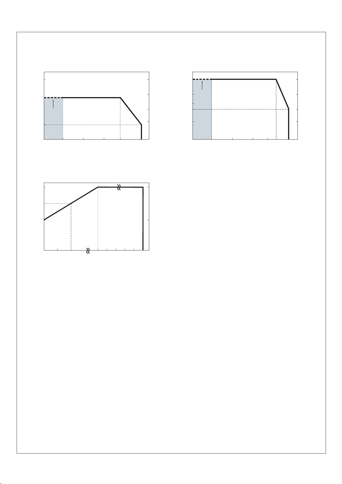
4.1 Derating
◎ When PHP-3500 is operating at a lower AC input voltage, the unit will derate its output current automatically to protect itself.
12
LOAD (%)
INPUT VOLTAGE (VAC) 60Hz
90 100 115 180 264
100
50
(HORIZONTAL)
70
AMBIENT TEMPERATURE WITH 128 CFM FAN*2 OR WATER
COOLING SYSTEM (℃)
5025 450-25-30
LOAD (%)
30
60
75
50
100
230VAC
Input only
(HORIZONTAL)
60
AMBIENT TEMPERATURE WITH ADDITIONAL ALUMINUM PLATE(℃)
(450x450x3mm)
o
Note. Tcase max.≦70 C and ambient temp must be within above
de-rating curve.
o
Note. Tcase max.≦45 C and ambient temp must be within above
de-rating curve.
25 400
230VAC
Input only
-25-30
LOAD (%)
20
60
100
60

4.2 External filter
4.3 Water Cooling System
4.3.1 water cold plate Quality requirement for surfaces
4.3.2 water cooling loop Operational requirement for
4.3.3 water cold plate Note on design
4.3.4 Condensation prevention and control
◎ . There should be no any shrinkage cavity, corrosion or cracks on the surfaces
◎ Using good quality water is recommended, resistance < ℃, 2.5KΩ and having a pH of 6-9; Inlet temperature of 25 flow rate
of 1 liter per .minute
◎ Please make sure there is no fluid leaks, blocks or condensation under operation.
◎ Material (purity, thickness, machining precision, etc) and manufacturing craft (whether there are cracks, fractures, etc
It is important to minimize or prevent condensation because condensate could drip onto electronics or collect in the bottom
of the system and cause corrosion. To avoid condensation, please follow below:
◎ Flatness between mating parts plays a critical role in thermal contact conductance.
◎ Please make sure cooling capacity of the chiller is greater than 175W so as to dissipate heat from the power supply efficiently.
◎ Temperature difference between the water and ambient temperature should be lower than ℃ in hot and humid places.5
◎ . Turn off the water cooling system during a power outage
caused by extrusion) have an profound impact on thermal conductivity of a cold plate.
13
LINE
1 3
Cx Cx
Cy
Cy
RL L
2 4
5
LOAD
4.2.2 Schematic
EMI
FILTER
AC Utility
LOAD
PHP-3500
AC
I/P
DC
O/P
4.2.1 Configration
FREQ. MHz
L Cx Cy
0.6mH 1.0uF 10000pF
0.01
2
4
0.05
5
15
0.10
8
18
0.15
10
18
0.50
30
45
1.0
35
50
5.0
55
40
10
45
40
30
30
40
COM. MODE dB
DIF. MODE dB
4.2.3 Minimum insertion loss (In dB at 50Ω system): Filter model 30DPGS5C or equivalent
Note : Need additional EMI filter to meet regulations of EMC conducted and radiated emission. Characteristics of EMI filter please refer to the table,
Minimum Insertion Loss.

Optional MEAN WELL cold plate is ready for order, Ordering No.: HS-656
4. 4 Warranty
◎ A five year global warranty is provided under normal operation. Please do not change any component or modify the unit by
yourself or MEANWELL may reserve the right not to provide the complete warranty service.
14
M5*6

N o . 28 , W u q ua n 3 rd R d . , Wu gu D i st . , N ew Tai p ei C i ty 24 8 , Ta iwa n
This manual suits for next models
3
Table of contents
Other Meanwell Industrial Equipment manuals


