PISCO VG Series User manual

106
VN
VZ
VQ
VX
VJ
VK
VG
VACUUM
GENERATOR
EXTERNAL VACUUM
CONTROLLER
VACUUM
PAD
VACUUM
ACCESSORIES
Complex Ejector focusing on basic performance
VacuumGenerator
VG
Series
●Vacuum switch and blow-off valve are united. Select the
best combination in accordance with applications.
●There are 3 output types: 1 switch output and 1 analog
output type, 2-point switch output type, and cost saving
1 analog output type.
Air supply port (P)
Valve unit
(Suction valve / Blow-off valve)
Vacuum port (V)➡
Blow-off air rate adjustment needle
Ejector unit
Vacuum switch
Filter

Vacuum Generator Series
Vacuum Generator VG
VH · VS
107
VU
VB
VM · VC
VG
VY
VUM
VRL
VACUUM
GENERATOR
■ Model Designation (Example)
EVG F 4
⑤ Air supply port size
④
Vacuum port size
①
Vacuum characteristics
③
Combination of units
07
②
Nozzle bore
4
⑤
Air supply port size
DC24
⑥
Valve unit voltage spec
① Vacuum characteristics
② Nozzle bore
Complex Vacuum Generator
L
⑦
Wire lead-out direction
NA
⑧
Vacuum Switch
③ Combination of units ④ Vacuum port size
⑥ Valve unit voltage spec
⑦ Wire lead-out direction
⑧ Vacuum Switch (For Unit combination of B and F only)
Code
H
Performance
High-vacuum type
Code
L
Performance
Large-flow type
Code
E
Performance
High-vacuum at low air supply pressure type
Code
05
07
10
Nozzle
bore
0.5mm
0.7mm
1.0mm
H type
Vacuum level, Suction flow
-90kPa
7l/min(ANR)
-93kPa
13l/min(ANR)
-93kPa
27l/min(ANR)
L type
Vacuum level, Suction flow
-66kPa
12l/min(ANR)
-66kPa
26l/min(ANR)
-66kPa
40l/min(ANR)
E type
Vacuum level, Suction flow
–
-90kPa
10.5l/min(ANR)
-90kPa
21l/min(ANR)
Air consumption
11. 5 l/min(ANR)
23l/min(ANR)
(17l/min(ANR))
46l/min(ANR)
(34l/min(ANR))
※Supply pressure is 0.5MPa for H and L type and 0.35MPa for E type.
※The values of air consumption in ( ) are for E type.
※The values in the table are representative values. Suction flow can vary by vacuum port dia. or tube length.
Code
A
B
E
F
Filter
○
○
○
○
Vacuum switch
-
○
-
○
Suction valve
-
-
○
○
Blow-off valve
-
-
○
○
Joint type
Code
Size
Push-In Fitting
4
ø4mm
6
ø6mm
Joint type
Code
Size
Push-In Fitting
4
ø4mm
6
ø6mm
Code
Voltage
DC24
DC24V
AC100
AC100V
Code
lead-out direction
S
Side
L
To p
Code
Sensor
NW
2 Switch outputs
NA
1 analog output and 1 switch output
A
1 analog output

108
VN
VZ
VQ
VX
VJ
VK
VG
VACUUM
GENERATOR
EXTERNAL VACUUM
CONTROLLER
VACUUM
PAD
VACUUM
ACCESSORIES
■ Specication
■ Suction Valve Specication
■ Blow-o Valve Specication
■ Vacuum Switch Specication
Fluid medium Air
Operating pressure range
0.25 ~ 0.7MPa
Operating temp. range 5 ~ 50°C
Lubrication Not required
Valve type Pilot operated poppet valve
Rated voltage DC24V ±10%・AC100V ±10%
Power consumption 1.2W (with LED)・1.5VA (with LED)
Eective sectional area
5 mm2
Manual operation Push button (non-lock)
Valve type Direct operating poppet
Rated voltage DC24V ±10%・AC100V ±10%
Power consumption 1.2W (with LED)・1.5VA (with LED)
Manual operation Push button (non-lock)
Model code
Output Specication
Power requirements
Current consumption (when 24VDC supplied)
Fluid medium
Operating pressure range
Proof pressure
Operating temp. range
Operating humidity range
Durability ( ※ )
No. of pressure setting
Switch output
Pressure setting range
Switch output
Operating accuracy
Dierential response
Switch capacity
Residual voltage
Output voltage
Analog output
Zero point voltage
Span voltage
Lin / HYS
DC12 ~ 24V ±10% 24VDC ±Ripple (P-P) Max. 10%
Variable (about 1-15% of set value)
VG······-NA
1 switch output
1 analog output
NPN open collector output
0 ~-100 kPa
±3%F.S. (at 25°C)
VG······-NW
2 switch output
VG······-A
1 analog output
Max. 17mA (1 switch: ON)
Max. 25mA (2 switches: ON)
Max. 15mA (Output current: 0mA)
Air / Inert gas
0 ~-100kPa
200kPa
0 ~50°C (No freezing)
35 ~85%RH (No dew condensation)
10 million cycles (0 ~ rated pressure)
1 2
2% F.S.Max
30V DC 80mA Max.
Max. 0.8V
1 ~5V
1 ±0.1V
4 ±0.1V
±0.5%F.S.以下
1 ~5V
1 ±0.2V
4 ±0.2V
±0.5%F.S.以下
* Allowable range: ±3%F.S. of zero point voltage, Span voltage for analog output, or of switch output accuracy.

Vacuum Generator Series
Vacuum Generator VG
VH · VS
109
VU
VB
VM · VC
VG
VY
VUM
VRL
VACUUM
GENERATOR
■ Filter Specication
■ Characteristics
0 0 5 10 15 20
–13
–26
–40
–53
–66
–80
–93
–13
–26
–40
–53
–66
–80
–93
0.1 0.2 0.3 0.4 0.5 0.6
Supply pressure (MPa) Suction flow (l/min(ANR))
Final vacuum (kPa)
Vacuum pressure (kPa)
Flow rate (l/min(ANR))
VGH05, VGL05
Vacuum characteristics Flow characteristics
H type Final vacuum
H type suction flow
L type suction flow
Air consumption
L type Final vacuum
0
5
10
15
20
H type
L type
Supply pressure:0.5MPa (H, L type)
0 0 10 20 30
–13
–26
–40
–53
–66
–80
–93
–13
–26
–40
–53
–66
–80
–93
0.1 0.2 0.3 0.4 0.5 0.6
Supply pressure (MPa) Suction flow (l/min(ANR))
Final vacuum (kPa)
Vacuum pressure (kPa)
Flow rate (l/min(ANR))
VGH07, VGL07, VGE07
Vacuum characteristics Flow characteristics
0
10
20
30
40
50
40
H type
E type
L type
H type Final vacuum
L type Final vacuum
E type Final vacuum
H type suction flow
E type suction flow
L type suction flow
Air consumption
Supply pressure:0.5MPa (H, L type)
0.35MPa (E type)
0 0 10 20 30 40
–13
–26
–40
–53
–66
–80
–93
–13
–26
–40
–53
–66
–80
–93
0.1 0.2 0.3 0.4 0.5 0.6
Supply pressure (MPa) Suction flow (l/min(ANR))
Final vacuum (kPa)
Vacuum pressure (kPa)
Flow rate (l/min(ANR))
VGH10, VGL10, VGE10
Vacuum characteristics Flow characteristics
0
10
20
30
40
50
60
70
H type
E type
L type
H type Final vacuum
L type Final vacuum
E type Final vacuum
H type suction flow
E type suction flow
L type suction flow
Air consumption
Supply pressure:0.5MPa (H, L type)
0.35MPa (E type)
Element material PVF(Polyvinyl formal)
Filtering capacity 10µm
Element model code VGFE10
Supply pressure - Final vacuum / Suction Flow / Air Consumption

110
VN
VZ
VQ
VX
VJ
VK
VG
VACUUM
GENERATOR
EXTERNAL VACUUM
CONTROLLER
VACUUM
PAD
VACUUM
ACCESSORIES
■ How to insert and disconnect
1. How to insert and disconnect tubes
①Tube insertion
Insert a tube into Push-In Fitting of the vacuum generator VG up to the tube
end. Lock-claws bite the tube to fix it and the elastic sleeve seals around the
tube.
Refer to “2. Instructions for Tube Insertion”under “Common Safety Instructions
for Fittings”.
②Tube disconnection
The tube is disconnected by pushing release-ring to release Lock-claws.
Make sure to stop air supply before the tube disconnection.
2. How to fix the product
In order to fix the vacuum generator VG, tighten M3 threads
through the fixing holes on the resin body with tightening
torque 0.3 to 0.35Nm. Refer to the outer dimensional
drawings for the hole pitch.

Vacuum Generator Series
Vacuum Generator VG
VH · VS
111
VU
VB
VM · VC
VG
VY
VUM
VRL
VACUUM
GENERATOR
Vacuum
Suction pilot valve
Blow-off valve
Ejector
Silencer
Vacuum switch
Filter
Air source
Ejector
Air source
Silencer
Filter
Vacuum
Air source
Vacuum switch
Vacuum
Ejector
Silencer
Filter
Suction pilot valve
Blow-off valve
Vacuum
Ejector
Silencer
Filter
Air source
■ Standard Size List
■ Applicable Tubes and Related Products
Type
Page
to refer
Air supply
port
Vacuum port
4mm
VG A Type 112 4mm
6mm
●
6mm
●
Type
Page
to refer
Air supply
port
Vacuum port
4mm
VG B Type 112 4mm
6mm
●
6mm
●
Type
Page
to refer
Air supply
port
Vacuum port
4mm
VG
E Type
113 4mm
6mm
●
6mm
●
Type
Page
to refer
Air supply
port
Vacuum port
4mm
VG
F Type
114 4mm
6mm
●
6mm
●
Unit combination : Built-in Filter Type Unit combination: Vacuum Switch (digital type) / Built-in Filter Type
Unit combination: Suction Valve / Blow-off Valve / Built-in Filter Type Unit combination: Vacuum Switch (digital type) / Suction Valve
/ Blow-off Valve / Built-in Filter
Polyurethane Tube
(Piping products catalog P.596)
■ Polyurethane Tube is for the general
pneumatic piping and suitable for a
compact piping.
Nylon Tube
(Piping products catalog P.608)
■ Nylon Tube is for the general pneumatic
piping and suitable for a high-pressure fluid
up to 1.5MPa (NB tube: 1.0MPa).
Vacuum Tube
(Piping products catalog P.612)
■ Vacuum Tube is a ultra-soft tube and
suitable for piping of vacuum generators or
actuators.
Vacuum Pads
●Vacuum Pad Standard Series ・・ P.428
●Vacuum Pad Sponge Series ・・・ P.468
●Vacuum Pad Bellows Series ・・・ P.488
●Vacuum Pad Multi-Bellows Series P.508
●Vacuum Pad Oval Series ・・・・・ P.526
●Vacuum Pad Soft Series ・・・・・ P.550
●Vacuum Pad Soft Bellows Series ・ P.578
●Vacuum Pad Skidproof Series ・・ P.604
●Vacuum Pad Ultrathin Series ・・・ P.624
●Vacuum Pad Mark-free Series ・・ P.642
●Vacuum Pad Long Stroke Series ・ P.658

112
VN
VZ
VQ
VX
VJ
VK
VG
VACUUM
GENERATOR
EXTERNAL VACUUM
CONTROLLER
VACUUM
PAD
VACUUM
ACCESSORIES
VG
2-ø3.2
50
14
3
13.5
20
14
37 L2L1
3
V
P
2-øD
2-C
10
A Type Built-in Filer Type
Ejector
Air source Silencer
Filter
Vacuum
VG
2-ø3.2
56
About 500
6
14
313.5
20
14
52 L2L1
3
VP
2-øD
2-C
-NA
:
Hysteresis setting trimmer
-NW:SW2 Vacuum setting trimmer
-NA:SW Vacuum setting trimmer
-NW:SW1 Vacuum setting trimmer
Operation indicator LED
10
※1 analog output type does not have Operation indicator LED and Vacuum Setting Trimmer.
Vacuum Sensor (digital type) / Built-in Filter Type
Air source
Vacuum sensor
Vacuum
A Type
B Type
CAD
-
2D
-
Chart
P.109
CAD
-
2D
-
Chart
P.109
Unit:mm
Model
code
Tube O.D.
øD L1 L2 C
Nozzle Bore
(mm)
Final vacuum
(-kPa)
Suction flow
(l/min(ANR))
Air consumption
(l/min(ANR))
Weight
(g)
CAD
file name
VGH05A-44 49.6 9.1 10.9 0.5 90 7 11.5 47
VVG-001
VGH07A-66 612.1 11.6 11.7 0.7 93 13 23 49
VGH10A-66 1 27 46 48
VGL05A-44 49.6
9.1
10.9 0.5
66
12 11.5 46
VGL07A-66 612.1 11.6 11.7 0.7 26 23 48
VGL10A-66 1 40 46 47
VGE07A-66 612.1
11.6
11.7 0.7 90 10.5 17 48
VGE10A-66 1 21 34
Unit:mm
Model
code
Tube O.D.
øD L1 L2 C
Nozzle Bore
(mm)
Final vacuum
(-kPa)
Suction flow
(l/min(ANR))
Air consumption
(l/min(ANR))
Weight
(g)
CAD
file name
VGH05B-44- □
49.6 7.6 10.9 0.5 90 7 11.5 74
VVG-001
VGH07B-66- □
612.1 10.1 11.7 0.7 93 13 23 75
VGH10B-66- □
1 27 46
VGL05B-44- □
49.6
7.6
10.9 0.5
66
12 11.5 73
VGL07B-66- □
612.1 10.1 11.7 0.7 26 23 75
VGL10B-66- □
1 40 46 74
VGE07B-66- □
612.1
10.1
11.7 0.7 90 10.5 17 75
VGE10B-66- □
1 21 34 74
compliant
compliant
CAD
-
2D
-
CAD data is available at PISCO website.Characteristic chart page
Chart
P.000
Circuit
Circuit

Vacuum Generator Series
Vacuum Generator VG
VH · VS
113
VU
VB
VM · VC
VG
VY
VUM
VRL
VACUUM
GENERATOR
VG
4-ø3.2
About 500
7.5
313.5
50
30.1 26
6
20
14
(18)
3
14 6
52 L2
14.5
L1
3 3
VP
2-øD
16.5
Blow-off air adjustment
release needle
14.5
2-C
Manual button
LED
Blow-off valve
Suction pilot valve
Suction Pilot Valve / Blow-off Valve / Built-in Filter Type
Cable lead-out direction: Top
Pilot valve
Blow-off valve Vacuum
Air source
VG
4-ø3.2
About 500
7.5
313.5
50
30.1
20.7
6
20
14
3
14
(18)
6
52 L2
14.5
L1
3 3
VP
2-øD
16.5
Blow-off air adjustment
release needle
Manual button
LED
Blow-off valve
Suction pilot valve
14.5
19.9
2-C
Suction Pilot Valve / Blow-off Valve / Built-in Filter Type
Cable lead-out direction: Side
Pilot valve
Blow-off valve Vacuum
Air source
E-L Type
E-S Type
CAD
-
2D
-
Chart
P.109
CAD
-
2D
-
Chart
P.109
Unit:mm
Model
code
Tube O.D.
øD L1 L2 C
Nozzle Bore
(mm)
Final vacuum
(-kPa)
Suction flow
(l/min(ANR))
Air consumption
(l/min(ANR))
Weight
(g)
CAD
file name
VGH05E-44- □L
49.6 7.6 10.9 0.5 90 7 11.5 99
VVG-001
VGH07E-66- □L
612.1 10.1 11.7 0.7 93 13 23 100
VGH10E-66- □L
1 27 46 101
VGL05E-44- □L
49.6
7.6
10.9 0.5
66
12 11.5 99
VGL07E-66- □L
612.1 10.1 11.7 0.7 26 23 101
VGL10E-66- □L
1 40 46 100
VGE07E-66- □L
612.1
10.1
11.7 0.7 90 10.5 17 101
VGE10E-66- □L
1 21 34 100
Unit:mm
Model
code
Tube O.D.
øD L1 L2 C
Nozzle Bore
(mm)
Final vacuum
(-kPa)
Suction flow
(l/min(ANR))
Air consumption
(l/min(ANR))
Weight
(g)
CAD
file name
VGH05E-44- □S
49.6 7.6 10.9 0.5 90 7 11.5 99
VVG-001
VGH07E-66- □S
612.1 10.1 11.7 0.7 93 13 23 100
VGH10E-66- □S
1 27 46 101
VGL05E-44- □S
49.6
7.6
10.9 0.5
66
12 11.5 99
VGL07E-66- □S
612.1 10.1 11.7 0.7 26 23 101
VGL10E-66- □S
1 40 46 100
VGE07E-66- □S
612.1
10.1
11.7 0.7 90 10.5 17 101
VGE10E-66- □S
1 21 34 100
compliant
compliant
CAD
-
2D
-
CAD data is available at PISCO website.Characteristic chart page
Chart
P.000
Circuit
Circuit

114
VN
VZ
VQ
VX
VJ
VK
VG
VACUUM
GENERATOR
EXTERNAL VACUUM
CONTROLLER
VACUUM
PAD
VACUUM
ACCESSORIES
VG
About 500
6
4-ø3.2
313.5
56
14
2-C
14(33)
67 L2L1
3
VP
2-øD
16.5
About 500
7.5
30.1 26
6
20
36
14.5
Blow-off air rate
adjustment needle
Manual button
LED
Blow-off valve
Suction pilot valve
14.5
Operation indicator LED -NA:SW Vacuum setting trimmer
-NW:SW1 Vacuum setting trimmer
-NA:Hysteresis setting trimmer
-NW:SW2 Vacuum setting trimmer
※
1 analog output type does not have Operation indicator LED and Vacuum Setting Trimmer.
Vacuum Sensor (digital type) / Suction Pilot Valve / Blow-off Valve / Built-in Filter
TypeCable lead-out direction: Top
Vacuum
Air source
VG
About 500
4-ø3.2
313.5
56 6
14 14(33)
67 L2L1
3
VP
2-øD
16.5
30.1
20.7
About 500
7.5
6
20
36
14.5
Blow-off air rate
adjustment needle
Manual button
LED
Blow-off valve
Pilot valve
14.5
19.9
2-C
-NA:Hysteresis setting trimmer
-NW:SW2 Vacuum setting trimmer
-NA:SW Vacuum setting trimmer
-NW:SW1 Vacuum setting trimmer
Operation indicator LED
※1 analog output type does not have Operation indicator LED and Vacuum Setting Trimmer.
Vacuum Sensor (digital type) / Suction Pilot Valve / Blow-off Valve / Built-in Filter Type
Cable lead-out direction: Side
Vacuum
Air source
F-L Type
F-S Type
CAD
-
2D
-
Chart
P.109
CAD
-
2D
-
Chart
P.109
Unit:mm
Model
code
Tube O.D.
øD L1 L2 C
Nozzle Bore
(mm)
Final vacuum
(-kPa)
Suction flow
(l/min(ANR))
Air consumption
(l/min(ANR))
Weight
(g)
CAD
file name
VGH05F-44- □L- □
49.6 7.6 10.9 0.5 90 7 11.5 125
VVG-001
VGH07F-66- □L- □
612.1 10.1 11.7 0.7 93 13 23 128
VGH10F-66- □L- □
1 27 46 127
VGL05F-44- □L- □
49.6
7.6
10.9 0.5
66
12 11.5
127
VGL07F-66- □L- □
612.1 10.1 11.7 0.7 26 23
VGL10F-66- □L- □
1 40 46
VGE07F-66- □L- □
612.1
10.1
11.7 0.7 90 10.5 17 128
VGE10F-66- □L- □
1 21 34
Unit:mm
Model
code
Tube O.D.
øD L1 L2 C
Nozzle Bore
(mm)
Final vacuum
(-kPa)
Suction flow
(l/min(ANR))
Air consumption
(l/min(ANR))
Weight
(g)
CAD
file name
VGH05F-44- □S- □
49.6 7.6 10.9 0.5 90 7 11.5 125
VVG-001
VGH07F-66- □S- □
612.1 10.1 11.7 0.7 93 13 23 128
VGH10F-66- □S- □
1 27 46 127
VGL05F-44- □S- □
49.6
7.6
10.9 0.5
66
12 11.5
127
VGL07F-66- □S- □
612.1 10.1 11.7 0.7 26 23
VGL10F-66- □S- □
1 40 46
VGE07F-66- □S- □
612.1
10.1
11.7 0.7 90 10.5 17 128
VGE10F-66- □S- □
1 21 34
compliant
compliant
CAD
-
2D
-
CAD data is available at PISCO website.Characteristic chart page
Chart
P.000
Circuit
Circuit

Vacuum Generator Series
Vacuum Generator VG
VH · VS
115
VU
VB
VM · VC
VG
VY
VUM
VRL
VACUUM
GENERATOR
Detailed Safety Instructions
Before using PISCO products, be sure to read “Safety Instructions” and “Safety Instruction
Manual” on page 35-39, “Common Safety Instructions for Vacuum Series” on page 47-49
and “Common Safety Instructions for Vacuum Generator VG & VK” on page 105.
Warning
1.
Attentions should be paid when pipe resistance is large or a large amount of blow-off air rate is required.
Insufficient blow-off air may cause troubles. Make sure to evaluate PISCO products by actual system.
2.
The coil in a pilot valve generates heat under the following ①-③conditions. Heating may be a cause of
dropping life cycle, malfunctions and burn or may affect negatively on peripheral machines due to the heat.
Contact us when the power is applied to the vacuum generator under the following conditions:
①The power is continuously ON for over 2 hours.
②High-cycle operation.
③Even when intermittent running of the generator is carried out, the total operation time per day is
longer than non-operation time.
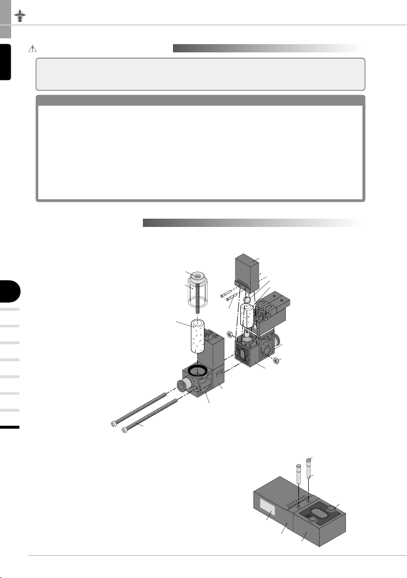
■ Replacement Element
■Remove the fixing screws to replace filter elements. Make sure not to lose the filter seal ring after the
replacement and tighten the screws with tightening torque 0.18-0.22Nm.
Silencer cover
Filter cover
Filter element
Model code:VGFE10
Filter unit
Vacuum sensor
Valve unit assembly
Ejector body
Hexagonal nut
Round head screw
Fixing Pin
Silencer element
Model code:SEE0602
Model code:VGED-G
■Replacement of Silencer Elements
Replace elements after removing 2 round head screws and 2 fixing pins.
※Make sure not to lose 2 hexagonal nuts.
■Procedures After Replacing Silencer Element
As the right figure shows, attach the silencer cover to the
ejector body and insert thinner end of 2 fixing pins into the
holes from the side with protrusion of the ejector body. Make
sure all seal materials of each unit are fit before assembling
the units. Use a screwdriver to appropriately tighten the
round head screw and the hexagonal nut with 0.35-0.4Nm
of the tightening torque.
Protrusion
Thinner end
Fixing Pin
Marking side
Fixing screw
Silencer cover
Ejector body

116
VN
VZ
VQ
VX
VJ
VK
VG
VACUUM
GENERATOR
EXTERNAL VACUUM
CONTROLLER
VACUUM
PAD
VACUUM
ACCESSORIES
■ Manual of Vacuum Sensor
■ Adjusting Method of Blow-o Air
■ Attaching / Detaching Individual Plug-in Connector
P
Air rate: ReduceAir rate: Increase
Blow-off air rate adjustment needle
Locknut
(~)Blue (~)Blue
+ -
(Black)
0V
(Red)
+V
Note) ( ) is the lead color.
■DC24V ■AC100V
■Backside of connector
Latch
(Latch) 0V
(Red) +V
1. Pressure Adjustment
① Turn on the power (Apply DC power to the vacuum sensor after making sure the correct wiring).
② Fully turn the hysteresis setting trimmer (HYS) in the counter-clockwise direction in order to minimize the
hysteresis setting. (Vacuum sensor with analog output (Code: -NA) only)
Note) When vacuum level is not stable, minimized hysteresis make the output unstable.
③ Adjust the vacuum setting trimmer (S1 / S2 and SW) to meet the required value.
Note) Use a vacuum gauge or check in the actual system for setting pressure.
④ Apply the air pressure and check the operation.
(In case of Vacuum sensor with analog output (Code: -NA))
Switch output (SW): Operation indicator (Red LED) turns ON more than the set pressure.
(Vacuum sensor with 2 switch output (Code: -NW))
Switch output 1 (S1): Operation indicator (Red LED) turns ON more than the set pressure.
Switch output 2 (S2): Operation indicator (Green LED) turns ON more than the set pressure.
2.
Differential response setting (Vacuum sensor with analog output (Code: -NA) only)
①Differential response setting can be adjusted by the hysteresis setting trimmer (HYS).
②Differential response setting range is regulated within about 0-15% of the set value. Differential response
setting becomes large when the trimmer is turned in the clockwise direction.
③Confirmation of Hysteresis
Gradually increase and decrease the supply pressure around the set pressure value and read the value
from a vacuum gauge when operation indicator lamp turns ON/OFF. The difference in the displayed
values is taken as differential response.
④Hysteresis adjustment is useful for the following cases:
・
Increase differential response when pressure pulsates with output repeatedly showing small on/off movements.
・When an allowable range is to be set for the lowering of pressure.
■Adjusting Method of Blow-off Air
●Turn the release needle in the clockwise direction to reduce
blow-off air and counter-clockwise to increase.
※After adjustment of the blow-off air rate, make sure to
tighten the locknut to prevent the setting from changing
with attentions to the following ①and ②.
①
Without turning the needle, finger-tighten the lock nut clockwise until it touches needle-guide. Then
tighten the nut by turning 20 ~ 30°more by using proper tool.
②Be careful not to damage the thread by over tightening.
■Attaching / Detaching Individual Plug-in Connector
●Insert the connector into the socket until it stops.
■Connector Detaching Method
●Pull out the connector while pushing the latch to
the arrowed direction.

Vacuum Generator Series
Vacuum Generator VG
VH · VS
117
VU
VB
VM · VC
VG
VY
VUM
VRL
VACUUM
GENERATOR
V
+
(Brown)
SW OUT(Black)
ANALOG OUT(Gray)
COM(Blue)
Load
Main
circuit
V
+
(Brown)
SW1 OUT(Black)
SW2 OUT(Gray)
COM(Blue)
Load
Load
Main
circuit
V
+
(Brown)
ANALOG OUT(Gray)
COM(Blue)
Main
circuit
5
4
3
2
1
1008053260
Vacuum level (-kPa)
Analog output (V)
■Analog output characteristics
5. Safety Instructions
① Do not use the vacuum generator in location where it may be exposed to water, oil drop or dust, since it
is not the drip/dust proof.
②Do not use the vacuum generator in location where it may be exposed to inflammable or explosive gas,
liquid or atmosphere, since it is not an explosive-proof.
③ Do not use the sensor in atmosphere exceeding the range of application temperature or causing heat as
the vacuum generator malfunction may result.
④ When the positive pressure such as blow-off air is applied to the sensor, do not apply the pressure more
than 0.2MPa constantly.
⑤ Do not use it in an ambience of gas containing a corrosive substance.
⑥ Compressed air contains many kinds of drains such as water, oxidized oil, tar and other foreign
substances. Dehumidify the compressed air by using an after-cooler or a dryer and improve the air quality,
since those drains seriously impair the performance of the vacuum generator.
⑦ Supply a stable DC power to the product.
⑧ Add a surge absorption circuit to relays or solenoid valves, etc. which are to be connected with output
terminal and source terminal. Avoid any use which involves over 80mA in current.
⑨ Ground FG terminal when using a unit power source such as switching current.
⑩ Output terminals (lead wire color: black and gray) and other terminals should not be short circuited.
⑪ Do not apply excessive external impact on the sensor.
⑫ Wiring or ways by which noise is caused may cause troubles.
⑬ When adjusting pressure and the hysteresis setting, use the accompaied flathead screwdriver. Do not
apply an excessive force on the trimmer and slowly turn it within its rotation limits.
4. Wiring / Piping
( 1)Be sure to shut off the power supply before wiring.
( 2)In conducting the wiring, distinguish the wire colors and confirm the terminal output.
( 3)Refer to Chart 1. Connecting Method for wiring.
( 4)Do not give excessive tension or bending to the drawer cable.
( 5)The cable can be connected or disconnected from connector. In case of disconnection, please hold
connector and pull out the cable while pushing stop bar. Avoid connection and disconnection unless it is
absolutely necessary, for it will put burdens on the sensor board.
1 analog output and 1 switch output (-NA)
2 switch output (-NW) 1 analog switch (-A)
Chart 1. Connecting Method
3. Output Characteristics of 1 analog switch (Code: -A).

35
Safety Instructions
SAFETY Instructions
Warning
This safety instructions aim to prevent personal injury and damage to
properties by requiring proper use of PISCO products.
Be certain to follow ISO 4414 and JIS B 8370
ISO 4414:Pneumatic fluid power…Recomendations for the application of equipment
to transmission and control systems.
JIS B 8370:
General rules and safety requirements for systems and their components.
This safety instructions is classified into “Danger”, “Warning” and “Caution” depending on
the degree of danger or damages caused by improper use of PISCO products.
1. Selection of pneumatic products
① A user who is a pneumatic system designer or has sufficient experience
and technical expertise should select PISCO products.
② Due to wide variety of operating conditions and applications for PISCO
products, carry out the analysis and evaluation on PISCO products.
The pneumatic system designer is solely responsible for assuring that
the user's requirements are met and that the application presents no
health or safety hazards. All designers are required to fully understand
the specifications of PISCO products and constitute all systems based
on the latest catalog or information, considering any malfunctions.
2. Handle the pneumatic equipment with enough knowledge and experience
① Improper use of compressed air is dangerous. Assembly, operation
and maintenance of machines using pneumatic equipment should be
conducted by a person with enough knowledge and experience.
3. Do not operate machine / equipment or remove pneumatic equipment until
safety is confirmed.
① Make sure that preventive measures against falling work-pieces or
sudden movements of machine are completed before inspection or
maintenance of these machine.
② Make sure the above preventive measures are completed. A
compressed air supply and the power supply to the machine must be
off, and also the compressed air in the systems must be exhausted.
③ Restart the machines with care after ensuring to take all preventive
measures against sudden movements.
Danger
Hazardous conditions. It can cause death or serious
personal injury.
Warning
Hazardous conditions depending on usages. Improper use of
PISCO products can cause death or serious personal injury.
Caution
Hazardous conditions depending on usages. Improper use of PISCO
products can cause personal injury or damages to properties.
※. This safety instructions are subject to change without notice.

http://www.pisco.co.jp
36
Disclaimer
1. PISCO does not take any responsibility for any incidental or indirect
loss, such as production line stop, interruption of business, loss
of benefits, personal injury, etc., caused by any failure on use or
application of PISCO products.
2. PISCO does not take any responsibility for any loss caused by natural
disasters, res not related to PISCO products, acts by third parties, and
intentional or accidental damages of PISCO products due to incorrect
usage.
3. PISCO does not take any responsibility for any loss caused by improper
usage of PISCO products such as exceeding the specication limit or not
following the usage the published instructions and catalog allow.
4. PISCO does not take any responsibility for any loss caused by remodeling
of PISCO products, or by combinational use with non-PISCO products and
other software systems.
5. The damages caused by the defect of Pisco products shall be covered but
limited to the full amount of the PISCO products paid by the customer.

37
Safety Instructions
SAFETY INSTRUCTION MANUAL
Danger
1. Do not use PISCO products for the following applications.
① Equipment used for maintaining / handling human life and body.
② Equipment used for moving / transporting human.
③ Equipment specifically used for safety purposes.
Warning
1. Do not use PISCO products under the following conditions.
①
Beyond the specifications or conditions stated in the catalog, or the instructions.
② Under the direct sunlight or outdoors.
③ Excessive vibrations and impacts.
④
Exposure / adhere to corrosive gas, inflammable gas, chemicals, seawater, water and vapor. *
* Some products can be used under the condition above(④), refer to
the details of specification and condition of each product.
2. Do not disassemble or modify PISCO products, which affect the
performance, function, and basic structure of the product.
3.
Turn off the power supply, stop the air supply to PISCO products, and make sure
there is no residual air pressure in the pipes before maintenance and inspection.
4.
Do not touch the release-ring of push-in fitting when there is a working pressure.
The lock may be released by the physical contact, and tube may fly out or slip out.
5. Frequent switchover of compressed air may generate heat, and there is a
risk of causing burn injury.
6. Avoid any load on PISCO products, such as a tensile strength, twisting
and bending. Otherwise, there is a risk of causing damage to the products.
7. As for applications where threads or tubes swing / rotate, use Rotary
Joints, High Rotary Joints or Multi-Circuit Rotary Block only. The other
PISCO products can be damaged in these applications.
8.
Use only Die Temperature Control Fitting Series, Tube Fitting Stainless SUS316
Series, Tube Fitting Stainless SUS316 Compression Fitting Series or Tube Fitting
Brass Series under the condition of over 60℃ (140°F) water or thermal oil. Other
PISCO products can be damaged by heat and hydrolysis under the condition above.
9.
As for the condition required to dissipate static electricity or provide an antistatic
performance, use EG series fitting and antistatic products only, and do not use other PISCO
products. There is a risk that static electricity can cause system defects or failures.
10. Use only Fittings with a characteristic of spatter-proof such as Anti-
spatter or Brass series in a place where flame and weld spatter is
produced. There is a risk of causing fire by sparks.
11.
Turn off the power supply to PISCO products, and make sure there is
no residual air pressure in the pipes and equipment before maintenance.
Follow the instructions below in order to ensure safety.
①
Make sure the safety of all systems related to PISCO products before maintenance.
②
Restart of operation after maintenance shall be proceeded with care after
ensuring safety of the system by preventive measures against unexpected
movements of machines and devices where pneumatic equipment is used.
③ Keep enough space for maintenance when designing a circuit.
12. Take safety measures such as providing a protection cover if there is a
risk of causing damages or fires on machine / facilities by a fluid leakage.
PISCO products are designed and manufactured for use in general industrial
machines. Be sure to read and follow the instructions below.

http://www.pisco.co.jp
38
Caution
1. Remove dusts or drain before piping. They may get into the peripheral
machine / facilities and cause malfunction.
2. When inserting an ultra-soft tube into push-in fitting, make sure to place
an Insert Ring into the tube edge. There is a risk of causing the escape of
tube and a fluid leakage without using an Insert Ring.
3. The product incorporating NBR as seal rubber material has a risk of
malfunction caused by ozone crack. Ozone exists in high concentrations
in static elimination air, clean-room, and near the high-voltage motors,
etc. As a countermeasure, material change from NBR to HNBR or FKM is
necessary. Consult with PISCO for more information.
4. Special option “Oil-free” products may cause a very small amount of a fluid
leakage. When a fluid medium is liquid or the products are required to be
used in harsh environments, contact us for further information.
5. In case of using non-PISCO brand tubes, make sure the tolerance of the
outer tube diameter is within the limits of Table 1.
●Table 1. Tube O.D. Tolerance
mm size Nylon tube
Polyurethane tube
inch size Nylon tube
Polyurethane tube
ø1.8mm ─ ±0.05mm ø1/8 ±0.1mm ±0.15mm
ø3mm ─ ±0.15mm ø5/32 ±0.1mm ±0.15mm
ø4mm ±0.1mm ±0.15mm ø3/16 ±0.1mm ±0.15mm
ø6mm ±0.1mm ±0.15mm ø1/4 ±0.1mm ±0.15mm
ø8mm ±0.1mm ±0.15mm ø5/16 ±0.1mm ±0.15mm
ø10mm ±0.1mm ±0.15mm ø3/8 ±0.1mm ±0.15mm
ø12mm ±0.1mm ±0.15mm ø1/2 ±0.1mm ±0.15mm
ø16mm ±0.1mm ±0.15mm ø5/8 ±0.1mm ±0.15mm
6. Instructions for Tube Insertion
① Make sure that the cut end surface of the tube is at right angle without
a scratch on the surface and deformations.
② When inserting a tube, the tube needs to be inserted fully into the push-
in fitting until the tubing edge touches the tube end of the fitting as
shown in the figure below. Otherwise, there is a risk of leakage.
Tube end
Sealing
Tube is not fully inserted up to tube end.
③ After inserting the tube, make sure it is inserted properly and not to be
disconnected by pulling it moderately.
※.
When inserting tubes, Lock-claws may be hardly visible in the hole, observed
from the front face of the release-ring. But it does not mean the tube will
surely escape. Major causes of the tube escape are the followings;
①Shear drop of the lock-claws edge
②The problem of tube diameter (usually small)
Therefore, follow the above instructions from ① to ③ , even lock-claws
is hardly visible.

39
7. Instructions for Tube Disconnection
①
Make sure there is no air pressure inside of the tube, before disconnecting it.
② Push the release-ring of the push-in fitting evenly and deeply enough to
pull out the tube toward oneself. By insufficient pushing of the release-
ring, the tube may not be pulled out or damaged by scratch, and tube
shavings may remain inside of the fitting, which may cause the leakage
later.
8. Instructions for Installing a fitting
① When installing a fitting, use proper tools to tighten a hexagonal-column
or an inner hexagonal socket. When inserting a hex key into the inner
hexagonal socket of the fitting, be careful so that the tool does not
touch lock-claws. The deformation of lock-claws may result in a poor
performance of systems or an escape of the tube.
② Refer to Table 2 which shows the recommended tightening torque. Do
not exceed these limits to tighten a thread. Excessive tightening may
break the thread part or deform the gasket and cause a fluid leakage.
Tightening thread with tightening torque lower than these limits may
cause a loosened thread or a fluid leakage.
③ Adjust the tube direction while tightening thread within these limits,
since some PISCO products are not rotatable after the installation.
●Table 2: Recommended tightening torque / Sealock color / Gasket
materials
Thread type Thread size Tightening torque Sealock color Gasket materials
Metric thread
M3 ×0.5 0.7N·m
─
SUS304
NBR
M5 ×0.8 1.0 ~ 1.5N·m
M6 ×1 2 ~ 2.7N·m
M3 ×0.5 0.5 ~ 0.6N·m
POM
M5 ×0.8 1 ~ 1.5N·m
M6 ×0.75 0.8 ~ 1N·m
M8 ×0.75 1 ~ 2N·m
Taper pipe thread
R1/8 7 ~ 9N·m
White ─
R1/4 12 ~ 14N·m
R3/8 22 ~ 24N·m
R1/2 28 ~ 30N·m
Unified thread No.10-32UNF 1.0 ~ 1.5N·m─SUS304、NBR
National pipe
thread taper
1/16-27NPT 7 ~ 9N·m
White ─
1/8-27NPT 7 ~ 9N·m
1/4-18NPT 12 ~ 14N·m
3/8-18NPT 22 ~ 24N·m
1/2-14NPT 28 ~ 30N·m
※ These values may differ for some products. Refer to each specification as well.
9. Instructions for removing a fitting
① When removing a fitting, use proper tools to loosen a hexagonal-column
or an inner hex bolt.
② Remove the sealant stuck on the mating equipment. The remained
sealant may get into the peripheral equipment and cause malfunctions.
10.
Arrange piping avoiding any load on fittings and tubes such as twist,
tensile, moment load, shaking and physical impact. These may cause
damages to fittings, tube deformations, bursting and the escape of tubes.
Safety Instructions

Vacuum Generator Series
Vacuum Generator
47
VACUUM
GENERATOR
Common Safety Instructions for Vacuum Series
Warning
Before selecting or using PISCO products, read the following instructions. Read the
detailed instructions for individual series.
1. If there is a risk of dropping work-pieces during vacuum suction, take a safety
measure against the falling of them.
2. Avoid supplying more than 0.1MPa pressure constantly in a vacuum circuit.
Since vacuum generators are not explosive-proof, there is a risk of damaging
the products.
3. Pay attention to drop of vacuum pressure caused by problems of the supplied
air or the power supply. Decrease of suction force may lead to a danger
of falling work-piece so that safety measure against the falling of them is
necessary.
4. When more than 2 vacuum pads are plumbed on a single ejector and one of
them has a suction problem such as vacuum leak, there is a risk of releasing
work-pieces from the other pad due to the drop of the vacuum pressure.
5. Do not use in the way by which exhaust port is blocked or exhaust resistance
is increased. Otherwise, there is a risk of no vacuum generation or a drop of
the vacuum pressure.
6. Do not use the product in the circumstance of corrosive gas, inflammable
gas, explosive gas, chemicals, seawater and vapor or do not expose the
product to those. Never allow the product to suck those things.
7. Provide a protective cover on the products when it is exposed to sunlight.
8. Carry out clogging check for silencer element in an ejector and a vacuum
filter periodically. Clogged element will be a cause to impair the performance
or a cause of troubles.
9. Before replacing the element, thoroughly read and understand the method of
filter replacement in the catalog.
10. Make sure the correct port of the vacuum generator by this catalog or
marking on the products when plumbing. Wrong plumbing can be a risk to
damage the product.
11. Supply clean air without sludge or dusts to an ejector. Do not lubricate by a
lubricator. There is a risk of malfunction or performance impairing by impurities
and oil contained in the compressed air.
12. Do not apply extreme tension, twist or bending forces on a lead wire.
Otherwise, it may cause a wire breaking.
13. Locknut needs to be tightened firmly by hand. Do not use any tool to tighten.
In case of using tools to tighten the locknut, it may damage the locknut or the
product. Inadequate tightening may loosen the locknut and the initial setting
can be changed.
14. Do not force the product to rotate or swing even its resin body is rotatable. It
may cause damage to the product and a fluid leakage.
15. Do not supply an air pressure or a dry air to the products over the necessary
amount. There is a risk of deteriorating rubber materials and malfunction due
to oil.
16. Keep the product away from water, oil drops or dusts. These may cause
malfunction. Take a proper measure to protect the product before the
operation.

Chemical Name
Thinner
Carbon tetrachloride
Chloroform
Acetate
Aniline
Cyclohexane
Trichloroethylene
Sulfuric acid
Lactic acid
Water soluble cutting oil (alkaline)
* There are more chemicals which should be avoided. Contact us for the use under chemical circumstance.
48
VN
VZ
VQ
VX
VJ
VK
VG
VM · VC
VB
VU
VH · VS
VY
VUM
VRL
VACUUM
GENERATOR
EXTERNAL VACUUM
CONTROLLER
VACUUM
PAD
VACUUM
ACCESSORIES
Caution
1. Operating pressure range in the catalog is the values during ejector operation.
Secure the described value of the supplied air, taking a drop of the pressure
into consideration. Insufficient pressure, which does not satisfy the spec,
may cause abnormal noise, unstable performance and may negatively affect
sensors, bringing troubles at last.
2. Effective cross-section area of the air supply side needs to be three times as
large as effective cross-section area of the nozzle bore. When arranging piping
or selecting PISCO products, secure required effective cross-section area.
Insufficient supply pressure may be a cause to impair performance.
3. A Shorter distance of plumbing with a wider bore is preferable at vacuum
system side. A long plumbing with a small bore may result in slow response
time at the time of releasing work-piece as well as in failure to secure adequate
suction flow rate.
4. Plumb a vacuum switch and an ejector with vacuum switch at the end of
vacuum system as much as possible. A long distance between a vacuum
switch and a vacuum system end may increase plumbing resistance which
may lead to a high vacuum level at the sensor even when no suctioning and a
malfunction of vacuum switch. Make sure to evaluate the products in an actual
system.
5. Refer to “4. Instructions for Installing a fitting” and “5. Instructions for
Removing a fitting” under “Common Safety Instructions for Fittings” , when
installing or removing Fittings.
6. Refer to “Common Safety Instructions for Pressure Sensors” and “Detailed
Safety Instructions” for the handling of digital vacuum switch sensor.
7. Refer to “Common Safety Instructions for Mechanical Vacuum Sensor” for the
handling of mechanical vacuum switch.
8. The material of plastic filter cover for VG, VK, VJ, VZ and VX series is PCTG.
Avoid the adherence of Chemicals below to the products, and do not use them
under those chemical environments.
●Table Chemical Name
17. Do not use the product in the environment of inflammable or explosive gas /
fluid. It can cause a fire or an explosion hazard.
18. Do not use the product in the circumstance of corrosive gas, inflammable
gas, explosive gas, chemicals, seawater and vapor or do not expose the
product to those. Otherwise, it may be a cause of malfunction.
19. Do not clean or paint the products by water or a solvent.

Chemical Name
Methanol
Ethanol
Nitric acid
Sulfuric acid
Hydrochloric acid
Lactic acid
Acetone
Chloroform
Aniline
Trichloroethylene
Hydrogen peroxide
Vacuum Generator Series
Vacuum Generator
49
VACUUM
GENERATOR
9. The material of plastic filter cover for VQ and VFU series is PA. Avoid the
adherence of chemicals below to the products, and do not use them under
those chemical environments.
●Table Chemical Name
* There are more chemicals which should be avoided. Contact us for the use under chemical circumstance.
This manual suits for next models
48
Table of contents
Other PISCO Industrial Equipment manuals
Popular Industrial Equipment manuals by other brands

ABB
ABB HT590018 Operation manual

Hendrickson
Hendrickson ULTIMAAX 58K Technical Procedure

BLACKMER
BLACKMER HROF Installation and maintenance instructions

Interpack
Interpack CE-12P Operations manual & parts list

CM
CM Promarks Promax TMC-150 Operation manual

Heidolph
Heidolph LABOROTA 20 control automatic Series instruction manual