WITTUR OL20 User manual

© Copyright WITTUR 2016
www.wittur.com
OL20
No part of this publication may be reproduced or translated, even in part, without prior written permission
from WITTUR. We reserve the right to modify all specications and images included in these instructions.
Subject to change without notice!
OVERSPEED GOVERNOR
OPERATING INSTRUCTIONS
Code PM.7.005825.EN
Version -
Date 27.05.2021
*pM.7.005825.en$111*
Original instructions
Product manufacturer references can be found
on the name plate. For any support or further
questions please contact your local distributor.

Overspeed Governor
OL20
Operating instructions
Subject to change without notice! © Copyright WITTUR 2016
Content Page
Sheet PM.7.005825.EN.02
Version -
Date 27.05.2021
Approved WAT/KKR
1. General information prior to installation
1.1 Description and functions........................................................................................................ 4
1.2 Liability and guarantee ............................................................................................................ 5
1.3 Safety precautions .................................................................................................................. 5
1.4 Preparation ............................................................................................................................. 6
1.5 Advices for the work on safety components.............................................................................. 6
1.6 Scope of supply ...................................................................................................................... 7
2. Name plate, designation, identification
3. Mechanical installation and adjustment
3.1 General................................................................................................................................... 9
3.1.1 Handling of the OL20............................................................................................................... 9
3.1.2 Permissible Forces.................................................................................................................. 9
3.1.3 Fixing possibilities ................................................................................................................ 10
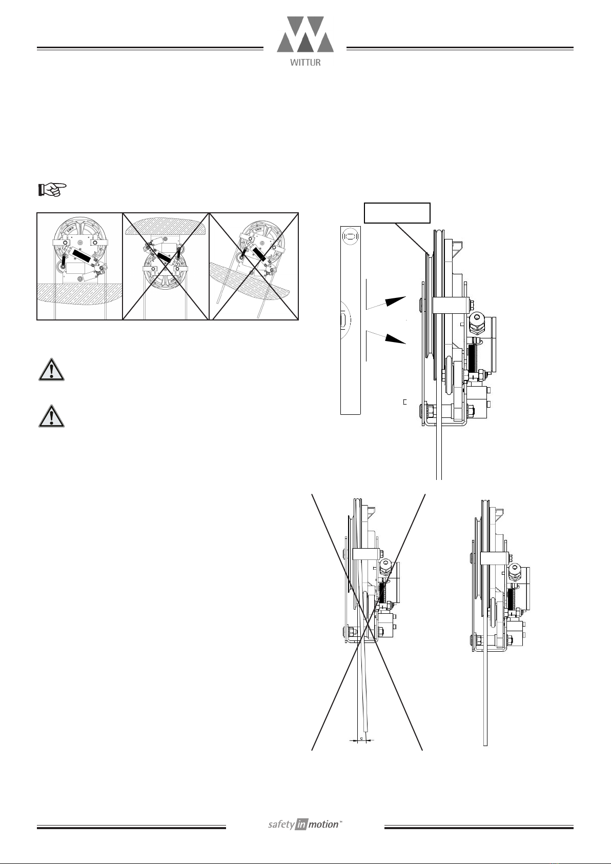
3.1.4 Installation tolerances ........................................................................................................... 10
3.1.5 Installation ........................................................................................................................... 10
3.2 Installing the overspeed governor........................................................................................... 11
3.2.1 Prior to installation................................................................................................................ 11
3.2.2 Installing in the machine room .............................................................................................. 12
3.2.3 Shaft head installation........................................................................................................... 13
3.3 Roping of the overspeed governor .......................................................................................... 14
3.4 Variants of OL20 overspeed governor arrangements ............................................................... 14
3.5 Electrical installation and adjustment..................................................................................... 15
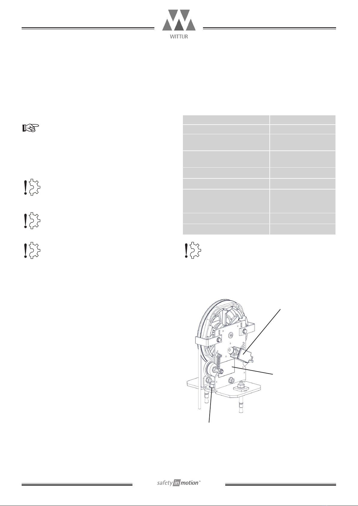
3.5.1 Overspeed contact ................................................................................................................ 15
3.5.2 remote control ...................................................................................................................... 16
3.6 Attaching the safety cover ..................................................................................................... 16
4. Function testing
4.1 Static function test:............................................................................................................... 18
4.1.1 Overspeed governor with manual tripping: .............................................................................. 18
4.1.2 Overspeed governor with remote control:................................................................................ 18
4.2 Dynamic function test............................................................................................................ 19
4.2.1 Check of the electrical tripping:.............................................................................................. 19
4.2.2 Check of mechanical tripping................................................................................................. 19
4.2.3 Check of tripping speed (CS / TS):.......................................................................................... 19
4.3 Tripping speed adjustment..................................................................................................... 20
5. Maintenance, inspection and repair
5.1 Maintenance and inspection .................................................................................................. 21
5.2 Mandatory checks/tests and periods...................................................................................... 21
5.3 Inspection checks ................................................................................................................. 22

Overspeed Governor
OL20
Operating instructions
Subject to change without notice! © Copyright WITTUR 2016
Sheet PM.7.005825.EN.03
Version -
Date 27.05.2021
Approved WAT/KKR
5.3.1 General checkings................................................................................................................. 22
5.3.2 Check the rope pulley ........................................................................................................... 22
5.3.3 Check the condition (wearing) of the wheel rope groove ......................................................... 22
5.3.4 Check the tripping pawl ......................................................................................................... 22
5.3.5 Check the adjustment spring.................................................................................................. 23
5.3.6 Check the condition of the wheel bearing ............................................................................... 23
5.3.7 Check the function of the overspeed contact .......................................................................... 23
5.4 Check the cleanness of the governor ..................................................................................... 23
5.5 Functional checks ................................................................................................................ 23
5.5.1 Tripping speed (CS/TS).......................................................................................................... 23
5.5.2 Brake force (lifting force) of the overspeed governor............................................................... 23
5.5.3 Measuring of the brake (lifting) force by 1/2 tension weight mass ........................................... 24
5.5.4 Measuring of the brake (lifting) force with force gauge............................................................ 24
5.6 Carrying out repairs............................................................................................................... 25
5.6.1 Tensioning the governor rope................................................................................................. 25
5.7 Spare parts ........................................................................................................................... 25
5.8 Operational lifetime of the Governor....................................................................................... 25
5.9 Disposal of waste.................................................................................................................. 25
6. Revision table

Overspeed Governor
OL20
Operating instructions
Subject to change without notice! © Copyright WITTUR 2016
Sheet PM.7.005828.EN.04
Version -
Date 27.05.2021
Approved WAT/KKR
1. General information prior to installation
1.1 Description and functions
The overspeed governor is a safety device that comes
into operation when the lift car exceeds its permitted
speed.
When the lift exceeds it’s nominal speed about a
predetermined value, the overspeed governor causes
the lift to stop, and in down direction if necessary also
causes the safety gear to be applied.
The basic functions of the governor are to detect
overspeed mechanical and electrically:
• to stop the elevator drive electrically
• to activate the safety gear mechanical
A tension weight is needed to tighten the rope of the
overspeed governor.
OL20
nominal speed 0,3 - 0,63m/s
0,7/1/1,5/1,6/1,75m/s
Rope diameter 6mm
Rope type steel wire rope bre core
Rope quality 1770N/mm²
System height max. 90m
Tension weight min. 400N
brake force min. 300N
Operating Temp. +5°C ... + 55°C *)
Storage Temp. -25°C ... + 60°C
*) For lifts according EN81: +5..... +40°C, General
temperature range if no tighter range is stated in the
local valid code: +5..... +55°C
If the nominal elevator speed is exceeded, the activation
bolt (1) on the tripping pawl (2) will hit the safety switch
(3) to switch off the safety circuit. If the speed still
increases, the tripping pawl (2) will grip into the rotating
trip wheel (4), which will block the governor wheel (5)
and activate the safety gear. If the force in the rope
exceeds the brake force, the rope in wheel starts to slip
inside the trip wheel groove. This is to protect rope and
the safety gear system from damage.
Travel upwards: In upwards direction the safety circuit
is switched off in the same way and at same speed as
for downwards direction. The safety gear will not be
activated in upward direction!
1. Rope pulley
2. Adjustment spring
3. Overspeed contact
4. Tripping pawl
5. Remote control magnet
6. Roller
7. Rope Guard
8. Cam

Overspeed Governor
OL20
Operating instructions
Subject to change without notice! © Copyright WITTUR 2016
Sheet PM.7.005828.EN.05
Version -
Date 27.05.2021
Approved WAT/KKR
1.2 Liability and guarantee
This instruction manual is written for people who are
familiar with elevator maintenance and installation.
Sufcient knowledge of elevators is essential.
WITTUR does not take responsibility for damage caused
by improper handling or for damage caused as a result
of actions other than those stated in these operating
instructions.
The WITTUR guarantee may be voided if parts other
than those described in these instructions are installed.
Unless stated otherwise, the following is not permissible
due to technical safety reasons:
• The use of components other than those installed,
• carrying out modications of any kind on the safety
gear,
• installing two different safety gears with different se-
rial numbers together,
• destruction of the seal. If the seal has been damaged,
the complete set of safety gears has to be replaced!
• Combining different component types,
• installing progressive safety gears intended for em-
ployments other than those stipulated,
• carrying out faulty or improper maintenance or in-
spection checks,
• using unsuitable accessories, spare parts or operat-
ing material which has neither been released by the
WITTUR company nor consists of original WITTUR
spare parts.
1.3 Safety precautions
Installers and maintenance personnel are fundamentally
responsible for their safety while working. The
monitoring and following of all valid safety rules and
legal conditions is required in order to prevent personal
injury and damage to materials during installation,
maintenance and repair work. This especially refers to
the corresponding accident prevention rules.
Important safety advice and danger warnings are
emphasized with the following symbols:
General danger warning
High risk danger warning (i.e. crushing edge,
cutting edge etc.)
Risk of damage on machinery parts (i.e. due to
incorrect installation etc.)
Important information sign
These operating instructions belong with the whole
installation and must be kept in a safe place at all times
(i.e. machine room).
The proper assembly and installation of WITTUR safety
gears requires correspondingly well-trained, tting
engineers. The responsibility of training lies with the
company appointed to carry out the work.

Overspeed Governor
OL20
Operating instructions
Subject to change without notice! © Copyright WITTUR 2016
Sheet PM.7.005828.EN.06
Version -
Date 27.05.2021
Approved WAT/KKR
Before starting installation work:
Only properly trained personnel may carry out installation
work or be allowed access to the installation site.
-Attach safety devices to guard oneself from falling
(platform or harnesses).
-Cover any oor openings.
-Secure installation tools or objects against
accidental falling.
-Elevator shaft openings should be cordoned off
and suitable warning signs should be erected when
working in shaft openings.
-Work involving electrical equipment should only
be carried out by an electrical engineer or qualied
personnel.
1.4 Preparation
Before starting assembly or installation work, it is in your
own interest to clarify the constructional and spatial
conditions as well as where (workshop or on site),
when and which installation operations can or must
be carried out. It is therefore recommended to take all
given circumstances into account and to plan various
operational sequences in advance, rather than carrying
them out prematurely and in an unconsidered manner.
On the receipt of the delivery, the goods or components
should be checked for correctness and completeness
with the order sheet.
The following should also be checked:
-The factory and the order number must correspond.
-The details on the name plate must correspond to
those on the order sheet.
-The elevator speed,
-the width and the type of guide rail used,
-the total load (mass to be gripped).
1.5 Advices for the work on safety components
Overspeed governors are classied as safety
components. It is most important for this product to
take into account all standards and guidelines described
in this section as well as other information given in this
operating manual.
These instructions, especially the section on
safety precautions, should be read and fully
understood before work begins.
Safety devices require special attention. Their proper
functioning is essential for a safe operation of the
system.
Safety devices which can only be adjusted after
installation must take place immediately after
installation.
If safety devices are already factory-preset, the function
of those must be checked and tested immediately.
Should it be necessary to disassemble a safety device
during servicing or repair, they are to be reassembled
and checked with the required tests and returned as the
work is carried out.

Overspeed Governor
OL20
Operating instructions
Subject to change without notice! © Copyright WITTUR 2016
Sheet PM.7.005828.EN.07
Version -
Date 27.05.2021
Approved WAT/KKR
1.6 Scope of supply
After delivery, the safety gear has to be checked for
damage and completeness. The scope of supply covers:
-Operating instructions manual
-Overspeed governor pre adjusted and calibrated at
the factory (right or left handed)
-Remote control (pre assembled; optional)
-different types of Safety covers
-different types of bases (optional)
-Mounting- and xing screw-packages

Overspeed Governor
OL20
Operating instructions
Subject to change without notice! © Copyright WITTUR 2016
Sheet PM.7.005828.EN.08
Version -
Date 27.05.2021
Approved WAT/KKR
2. Name plate, designation, identication
The overspeed governor OL20 identication indicators
are provided on the name plate which is located on the
front side of the governor
These consist of a name plate and an identication
sticker which gives the following data:
• Type term of overspeed governor
• Serial number
• Elevator number
• Nominal speed
• Safety circuit switch-off speed
• Mechanical tripping speed
• Rope diameter
The overspeed governor is pre-adjusted and
calibrated at the factory. No re-adjustment is
allowed.
Imaging of label
-EN81-20/50
Ground silver, letters black
Character style for datatable: Arial
Grund Silber, Schrift Schwarz
Schriftart Datentabelle: Arial
WITTUR
40
70
WITTUR
P01
Serial-No.:
Elevator-No.:
Prod.Date:
XXXXXXXAXX-SIDE-Y
OL20
CS
V
TS
V
#,##
m/s
#,##
m/s
#,##
m/s
V
NS
#,#
mm
Tripp. direction
Traceability
1068276P01
Type-Label (CB = EN81)
Wittur 11
ID No.
2D
Code
Wittur elevator components India Pvt. Ltd.
Survey nos 45/1B, 3&4, Pondur Village
Sriperumbudur - 602 105, Tamil Nadu, INDIA
Rope diam.:
Tripp. direction
right
left
Certificate number
Variable
Content according
(dependent on customer)
XXXXXXXAXX-SIDE-Y
XXXXXXX: main drawing nr.
AXX: OL Variant
SIDE: CAR or CWT (EN)
Y: Tripp direction (L/R)
Serial-No.
Serial number #########
Elevator-No.
Elevator number
Prod. Date
YYYY-MM-DD
V NS/ V
custom nominal speed
V CS/ V
adjusted contact speed
V TS/ V
adjusted tripping speed
custom rope diameter
2D Traceability
code according 904554
P01
R2211
Polyester For Labels
0.11
PART
TEIL
LOCAL INFO WAT
LOKALE INFO
WAT
ITEM NO.
ARTIKELNR.
DESCRIPTION
**...spec. acc. to WITTUR material datasheet
BESCHREIBUNG
**...Spez. lt. WITTUR Materialdatenbank
SURFACE TREATMENT
OBERFLÄCHENBEH.
MASS[kg]
MASSE[kg]
19/08/2021
AT1LatsLAT1LatsL
-
initial version
-
PCP01
A3
SIZE
2:1
SCALE
PRODUCT CODE
OL20
PRODUCT CATEGORY
7 - SAFETIES
ADD. DESCRIPTION
Type label
DESCRIPTION
1068276
DRAWING NUMBER
ISO1101
B
FUNCTIONAL CLASS
GT2
GEN. TOLERANCE WST-00033
ISO1302
ALLG. TOLERANZ WST-00033
GEOM. TOLERANZ SYMBOLEOBERFLÄCHE SYMBOLE
FUNKTIONSKLASSE
ZUS. BESCHREIBUNG
BESCHREIBUNG
ZEICHNUNGSNUMMER
ERSTE FREIGABE
DATUM
MAßSTAB
DATUM
INDEX
PRODUKTKATEGORIE
BLATT
FORMAT
GEZEICHNET VON
PRODUKTKODE
KONSTRUIERT
Typenschild
AT1LatsL
AT1LatsL
DATE
1/1
DESIGNED BY
SHEET
REVISION
FIRST APPROVAL
-
DATE
DRAWN BY
Checked
PCP01
17/12/2020
©WITTUR HOLDING GmbH
-
A
B
C
D
E
F
1 2 3 4 5 6 7 8
The reproduction, distribution and utilization of this document as well as the communication of its contents to others without express authorization
is prohibited. Offenders will be held liable for the payment of damages. All rights reserved in the event of the grant of a patent, utility model or design.
V5.0
Revision Qty.
Description
Change no.
Done by
Approved by
Date of issue
Weitergabe sowie Vervielfältigung dieses Dokuments, Verwertung und Mitteilung seines Inhalts sind verboten,
soweit nicht ausdrücklich gestattet. Zuwiderhandlungen verpflichten zu Schadenersatz.
Alle Rechte für den Fall der Patent-, Gebrauchsmuster- oder Geschmacksmustereintragung vorbehalten.
SURFACE TEXTURE SYMBOLS
GEOM. TOLERANCE SYMBOLS
nominal speed
v=(m/s)
Factory ID
Serialnumber
Traceability Code Tripping direction
Manufacturer
Type test
designation and
CE number
Rope diameter
(mm)
safety circuit switch
off speed (m/s)
Tripping speed
(m/s)
Date of manufacture

Overspeed Governor
OL20
Operating instructions
Subject to change without notice! © Copyright WITTUR 2016
Sheet PM.7.005828.EN.09
Version -
Date 27.05.2021
Approved WAT/KKR
3. Mechanical installation and adjustment
3.1 General
Check the direction of rotation: When the car /
counterweight travels downwards, the governor
has to rotate in the arrow direction. Arrow is
shown on type label. (Front side of governor)
3.1.1 Handling of the OL20
Do not lubricate the rope groove of the governor
rope pulley with any oil or grease This might
reduce the braking force!
Do not take/carry the governor by overspeed
contact or spring
Do not use hammers for any adjustment/
alignment actions!
Do not remove any assembly aids (cable ties) before both
mechanical installation and adjustment are nished!
3.1.2 Permissible Forces
OL20
Governor Weight ~5,3kg
max. tension force
(TW + rope mass) 1100N
Rope type steel wire rope bre
core (bright)
Rope diameter 6mm
Rope quality 1770N/mm²
min. breaking force of the
rope (in accordance with
EN 12385-5)
21KN
Tension weight min. 400N
brake force min. 300N
Only Governor ropes with low grade of lubrication
are allowed to be used!
M10x25 - 8.8
Arrow indicating the
governor tripping
direction
Electrication of the
safety circuit contact,
refer to wiring diagram

Overspeed Governor
OL20
Operating instructions
Subject to change without notice! © Copyright WITTUR 2016
Sheet PM.7.005828.EN.010
Version -
Date 27.05.2021
Approved WAT/KKR
3.1.3 Fixing possibilities
OL20 can only be xed in standing position
3.1.4 Installation tolerances
The over speed governor must be installed
vertically.
The overspeed governor must be installed in a
way so that the governor rope runs parallel into
the wheel groove!
The max. allowed tolerances are:
• Rope diameter = 6mm
3.1.5 Installation
The OL20 could be used at facilities according to
EN81-20.
Test groove

Overspeed Governor
OL20
Operating instructions
Subject to change without notice! © Copyright WITTUR 2016
Sheet PM.7.005828.EN.011
Version -
Date 27.05.2021
Approved WAT/KKR
3.2 Installing the overspeed governor
3.2.1 Prior to installation
Fixings of other brands than Wittur are outside
of the responsibility of our company and is not
guaranteed.
Basic governor xing position:
WITTUR
3
2
4
1
... N
Force shown
on force gauge
Tripping direction
A
90
2x
12
9
197
125
186
242
180
A
A
A1
SIZE
1:3
SCALE
PRODUCT CODE
OL20
PRODUCT CATEGORY
7 - SAFETIES
ADD. DESCRIPTION
Full Package
DESCRIPTION
1048860 for pictures
DRAWING NUMBER
GEOM. TOLERANCE SYMBOLS
ISO1101
A
FUNCTIONAL CLASS
GT1
GEN. TOLERANCE WST-00033
ISO1302
SURFACE TEXTURE SYMBOLS
AT1BaumD
DATE
1/1
DESIGNED BY
SHEET
REVISION FIRST APPROVAL
DATE
DRAWN BY
©WITTUR HOLDING GmbH
A
B
C
D
E
F
1 2345678
The reproduction, distribution and utilization of this document as well as the communication of its contents to others without express authorization
is prohibited. Offenders will be held liable for the payment of damages. All rights reserved in the event of the grant of a patent, utility model or design.
V5.0
Revision Qty.
Description
Change no.
Done by
Approved by
Date of issue
9 10 11 12
G
H
13 14 15 16
J
K
L
M

Overspeed Governor
OL20
Operating instructions
Subject to change without notice! © Copyright WITTUR 2016
Sheet PM.7.005828.EN.012
Version -
Date 27.05.2021
Approved WAT/KKR
3.2.2 Installing in the machine room
Observe the applicable safety measures when
working with elevator installations.
Installation procedure
Always pay attention to the overspeed governor
rotational direction during each stage of
installation.
1. If a supporting base is being used, it must be
screwed to the overspeed governor. (M10x25)
2. Position the overspeed governor (with or without
base) and align the plumb line over the center of
the pick up point on the synchronization.
3. Mark the drill holes and put the stud anchor in
place (stud anchors are delivered with supporting
base).
4. Fasten down the overspeed governor (with or
without supporting base).
Monitor the tightening torque.
Screw M10: 46Nm
Screw M12: 80Nm
Preparation
The overspeed governor can either be installed directly
on the machine room oor or on a support structure.
The dimension of holes in the slab and room
oor shall be reduced to a minimum for their
purpose.
With the aim of removing the danger of objects
falling throug openings situated above the well,
including those for electric cables, collar shall
be used, which project at least 50mm above the
slab or nished oor.
If a cement oor is to be poured over the concrete
after installation, bear this in mind when tting
the collar.
WITTUR
3
2
4
1
... N
Force shown
on force gauge
Tripping direction
A
190
125
13
40
130
A3
SIZE
1:3
SCALE
PRODUCT CODE
OL20
PRODUCT CATEGORY
7 - SAFETIES
ADD. DESCRIPTION
Full Package
DESCRIPTION
1048860 for pictures
DRAWING NUMBER
ISO1101
A
FUNCTIONAL CLASS
GT1
GEN. TOLERANCE WST-00033
ISO1302
AT1BaumD
DATE
1/1
DESIGNED BY
SHEET REVISION
FIRST APPROVAL
DATE
DRAWN BY
©WITTUR HOLDING GmbH
A
B
C
D
E
F
12345678
The reproduction, distribution and utilization of this document as well as the communication of its contents to others without express authorization
is prohibited. Offenders will be held liable for the payment of damages. All rights reserved in the event of the grant of a patent, utility model or design.
V5.0
Revision Qty.
Description
Change no.
Done by
Approved by
Date of issue
SURFACE TEXTURE SYMBOLS GEOM. TOLERANCE SYMBOLS

Overspeed Governor
OL20
Operating instructions
Subject to change without notice! © Copyright WITTUR 2016
Sheet PM.7.005828.EN.013
Version -
Date 27.05.2021
Approved WAT/KKR
3.2.3 Shaft head installation
Observe the applicable safety measures when
working with elevator installations.
Installation procedure
Always pay attention to the overspeed governor
rotational direction during each stage of
installation.
1. Check the layout drawing to see whether the
overspeed governor is to be fastened to the left- or
righthand guide rail.
2. Fix the support base to the rail at the desired
height.
The mounting holes are dependent upon the
model and guide rail used.
3. Position the overspeed governor and align the
plumb line over the center of the pick up point of
the synchronization.
4. Fasten the overspeed governor to the base.
Monitor the tightening torque.
Screw M10: 46Nm
Screw M12: 80Nm
The overspeed governor should be equipped
with remote tripping and remote reset for shaft
installation, or be easily externally accessible
(i.e. via an inspection door).
shaft head standing versionoptional shaft head hanging version

Overspeed Governor
OL20
Operating instructions
Subject to change without notice! © Copyright WITTUR 2016
Sheet PM.7.005828.EN.014
Version -
Date 27.05.2021
Approved WAT/KKR
3.3 Roping of the overspeed governor
The overspeed governor can only operate perfectly if
the governor rope and the tension weight are installed
correctly.
1. Leave enough extra length on the governor rope
and put it over the overspeed governor wheel.
2. Connect the rst rope end to the rope socket and
attach it to the safety gear.
3. Install the tension weight (refer to operating
instructions of tension weight).
4. Connect the second rope end to the rope socket of
the safety gear linkage.
3.4 Variants of OL20 overspeed governor arrange-
ments
OL20
Rope socket
Governor rope
Guide rail
Tension weight
Guide rail
Governor rope
Tension weight
OL20
Rope socket
Machine room less version
Machine room version

Overspeed Governor
OL20
Operating instructions
Subject to change without notice! © Copyright WITTUR 2016
Sheet PM.7.005828.EN.015
Version -
Date 27.05.2021
Approved WAT/KKR
3.5 Electrical installation and adjustment
3.5.1 Overspeed contact
Work involving electrical equipment should only
be carried out by an electrical engineer or qualied
personnel.
Check the power supply and the emergency
power supply before installing the overspeed
governor
Cut the power to all elevator parts before starting
installation work!
The contact is adjusted and sealed in the factory.
It is not allowed to be adjusted on site.
1. Connect the contact.
2. Test the contact function.
The detent pin must be pulled back to the initial
position by hand after being manually tested.
Overspeed contact data manual reset switch W013410
-2NC contacts
-use category: AC-15, DC-13;
-Ue/Ie: 240VAC (4A)
24VDC (1A)
-Ithe 10A
-Ui 500V
-Uimp 6kV
-protection type: IP 67
-approved in acc. with: IEC/EN 60947-5-1
Overspeed contact data manual reset switch W013408
-1NC contact
-use category: AC-15, DC-13;
-Ue/Ie: 230VAC (4A)
24VDC (4A)
-Ithe 10A
-Ui 250VAC
-Uimp 4kV
-protection type: IP 65
-approved in acc. with: VDE 0660 200,
IEC/EN 60947-5-1
Overspeed contact data electrical reset switch W013409
-2NC contacts
-use category: AC-15, DC-13;
-Ue/Ie: 230VAC (4A)
24VDC (4A)
-Ithe 10A
-Ui 250VAC
-Uimp 4kV
Electromagnet
-Uc: 24VAC/DC;
-Switch on time: 3%ED; tmax 5s
-protection type: IP 67
-approved in acc. with: IEC/EN 60947-5-1
Take note of the following when wiring the
connection cable:
• that the single polarity cables have double insulation
• that the use and wiring of cables is governed by the
EMC
The overspeed contact opens the lift installation’s
safety circuit.

Overspeed Governor
OL20
Operating instructions
Subject to change without notice! © Copyright WITTUR 2016
Sheet PM.7.005828.EN.016
Version -
Date 27.05.2021
Approved WAT/KKR
3.5.2 remote control
The remote control allows to trigger the overspeed
governor electrically in downward direction with rated or
service speed.
Power supply of the magnet:
-Voltage: 24VDC+10/-15%
-Current: 0,9 - 1,5A
-switch on time 5%ED
Power duration: tmax = 5s
3.6 Attaching the safety cover
The OL20 cover includes the rope guard. It is forbidden
to run the elevator without the cover or rope guard if
ordered.
A rope guard is generally prescribed for the
overspeed governor wheel
Variants:
1. no rope guard
2. basic rope guard (former EN81-1 conform)
3. basic rope guard with top cover plate (former
EN81-1 conform)
4. fully covered (EN81-20 conform)
pictures of safety cover
1.

Overspeed Governor
OL20
Operating instructions
Subject to change without notice! © Copyright WITTUR 2016
Sheet PM.7.005828.EN.017
Version -
Date 27.05.2021
Approved WAT/KKR
2.
3.
4.

Overspeed Governor
OL20
Operating instructions
Subject to change without notice! © Copyright WITTUR 2016
Sheet PM.7.005828.EN.018
Version -
Date 27.05.2021
Approved WAT/KKR
4. Function testing
Based on the proper installation of the elevator in
compliance with all regulations, it can be assumed that
the functionality of the system is guaranteed. Quality
and function of the individual components are subject to
strict controls and tested before factory shipment. Prior
to the initial acceptance and perhaps even prior to the
notied body tests, a functional review of the overspeed
governor should be performed.
First test run after installation:
Before the rst test run: If needed for proper
operation of Safety Gear: Carefully remove the
protective coating of grease from the guide rails!
Clean the guide rails!
Clear all people and objects from the elevator
shaft before commencing the test run.
Risk of crushing injuries!
The entire elevator travel path should be slowly traveled
(in inspection mode) before the function tests. Attention
should be paid to the clearance of all fastened parts,
especially with regards to the guide brackets/safety
gear devices. Find and remove any protruding bolts or
other dangerous restrictions in advance.
A static functions test should be carried out
afterwards.
4.1 Static function test:
4.1.1 Overspeed governor with manual tripping:
• Trigger the overspeed governor manually by lifting up
the tripping pawl with a screw driver
• Let the elevator car slowly descend by recalldrive
• Safety gear should stop the car
The overspeed governor must actuate the safety gear.
The overspeed contact must interrupt the safety circuit
by activating the overspeed contact.
4.1.2 Overspeed governor with remote control:
• Operate the remote tripping function.
• Let the elevator car slowly descend
• Safety gear should stop the car
The overspeed governor must actuate the safety gear.
The overspeed contact must interrupt the safety circuit
by activating the overspeed contact.
Reset the overspeed governor, the safety gear
and the overspeed contact by upward movement!

Overspeed Governor
OL20
Operating instructions
Subject to change without notice! © Copyright WITTUR 2016
Sheet PM.7.005828.EN.019
Version -
Date 27.05.2021
Approved WAT/KKR
4.2 Dynamic function test
In the following chapter, the checking of electrical
tripping, the release of the safety gear as well as the
verication of the tripping speed is described.
The operation of the electrical tripping (CS) must
be checked in both directions of movement
Electrical pre cut off only if ordered or above
1m/s nominal speed. Otherwise electrical
tripping occurs just before mechanical tripping.
Mechanical tripping only in down direction!
The dynamic function test can be carried out with or
without the elevator car rated load.
Nobody should be in the elevator car when
carrying out test runs or function tests!
After each test, the switch must be reset by
hand or by the use of the remote control.
4.2.1 Check of the electrical tripping:
• The switch can be tested with overspeed, in case the
elevator is able to simulate overspeed.
• Otherwise lay the governor rope in the test groove ->
if ordered (see image at 3.1.3) and let the elevator
car descend at rated speed. Therefore, remove the
rope guard
Don't forget to rebuild to initial functionality
before and after testing.
The overspeed governor must stop the elevator
electrically by interrupting the safety circuit.
4.2.2 Check of mechanical tripping
• Let the elevator car descend at rated speed.
• Trigger the speed governor manually (by lifting up the
tripping pawl with a screw driver) or by the use of the
remote control (similar to chapter 4, static function
test).
The overspeed governor must actuate the safety gear.
4.2.3 Check of tripping speed (CS / TS):
• Hoist the governor rope off from the wheel.
• Rotate the governor manually in tripping direction
and simultaneously measure the speed from the pul-
ley groove with a speedometer.
• Accelerate the rotation speed - as slow as possible -
until the speed governor triggers mechanically.
• Compare the measured value with the values given
in chapter 4.4.
• Reinstall the governor rope after successful testing!
The test must be repeated if the mechanical
tripping speed does not correspond with the
values in chapter 4.4.
The resulted gures may not be exactly (up to a
few percent) be the same as indicated on the
name plate. If they are, it is still correct.
Reason:
1. The gure in the label is the nominal as ordered
(for tolerances see 4.1).
2. The undened acceleration via hand possibly
causes different measuring results (acceleration
should be as little as possible, ~0.10m/s²).

Overspeed Governor
OL20
Operating instructions
Subject to change without notice! © Copyright WITTUR 2016
Sheet PM.7.005828.EN.020
Version -
Date 27.05.2021
Approved WAT/KKR
4.3 Tripping speed adjustment
Adjustment table acc. Wittur Standard
Safety Code CB = EN81-20 / GB7588 / IS14665
PRELIMINARY
PRELIMINARY
WITTUR
A
B
C
D
E
G
H
I
J
K
L
A
B
F
C
D
E
G
H
I
J
K
L
DETAIL B
DETAIL A
A
B
F
spring adjustment holes for
right version:
spring adjustment holes for
left version:
11/06/2021
11/06/2021
11/06/2021
11/06/2021
AT1BaumD
AT1BaumD
AT1BaumD
AT1KrieK
AT1BaumD
AT1BaumD
AT1BaumD
AT1BaumD
initial version
initial version
initial version
initial version
PCP04
PCP05
PCP06
-
A1
SIZE
1:2
SCALE
PRODUCT CODE
OL20
PRODUCT CATEGORY
7 - SAFETIES
ADD. DESCRIPTION
Stand Front
DESCRIPTION
1048860
DRAWING NUMBER
GEOM. TOLERANCE SYMBOLS
ISO1101
A
FUNCTIONAL CLASS
SM2
GEN. TOLERANCE WST-00033
ISO1302
SURFACE TEXTURE SYMBOLS
ALLG. TOLERANZ WST-00033
GEOM. TOLERANZ SYMBOLEOBERFLÄCHE SYMBOLE
FUNKTIONSKLASSE
ZUS. BESCHREIBUNG
BESCHREIBUNG
ZEICHNUNGSNUMMER
ERSTE FREIGABE
DATU M
MAßSTAB
DATU M
INDEX
PRODUKTKATEGORIE
BLATT
FORMAT
GEZEICHNET VON
PRODUKTKODE
KONSTRUIERT
AT1LatsL
IN1BalaE
DATE
3/3
DESIGNED BY
SHEET REVISION FIRST APPROVAL
11/06/2021
DATE
DRAW N BY
Work ing
-01
20/09/2019
©WITTUR HOLDING GmbH
krienka
A
B
C
D
E
F
1 2345678
The reproduction, distribution and utilization of th is document as well as the communication of its contents to others without express authorization
is prohibi ted. Offen ders will be held liab le for the paym ent of damag es. All rig hts reserv ed in the even t of the grant o f a patent, ut ility model o r design.
V5.0
Revision Qty.
Descri ption
Change no.
Done by Approved by
Date o f issue
9 10 11 12
G
H
13 14 15 16
J
K
L
M
Weitergabe sowie Vervielfälti gu ng dieses Dokuments, Verwertu ng und Mitteilung seines Inhalts si nd verboten,
soweit ni cht ausdrüc klich ges tattet. Zuw iderha ndlungen ve rpflic hten zu Scha denersatz .
Alle Rec hte für den Fal l der Patent-, G ebrauchsmuste r- oder Geschma cksmustereint ragung vorbeh alten.
According to EN81-20 / GB 7588 /IS14665
The overspeed governor is adjusted in the factory
to the following tripping speeds:
CAR Adjustment:
TSmax = 1,340 x NS NS < 1,00m/s
TSmax = 1,250 x NS NS ≥ 1,00m/s
TSmin = 0,900 x TS max CAR NS < 1,00m/s
TSmin = 0,945 x TS max CAR NS ≥ 1,00m/s
CSmin = 1,080 x NS
CSmax < TSadj. NS ≤ 1m/s
CSmax ≤ TSadj - 4% NS > 1m/s
CSmax ≤ TSadj - 4% (if pre cut off ordered)
CSup = TSmax
CWT Adjustment:
TSmax = 1,100 x TSmax CAR NS < 1,00m/s
TSmax = 1,050 x TSmax CAR NS ≥ 1,00m/s
TSmin = 0,005 x TSmax CAR
CSmin = 1,080 x NS
CSmax < TSadj. NS ≤ 1m/s
CSmax ≤ TSadj - 4% NS > 1m/s
CSmax ≤ TSadj - 4% (if pre cut off ordered)
CSup = TSmax
NS Nominal Speed
CS Contact Speed (of overspeed contact)
TS Tripping Speed
0.8 m/s for instantaneous except for the captive roller
type or 1.0 m/s for safety gears of the captive roller type
according to EN81-20 must be observed.
Table of contents
Other WITTUR Industrial Equipment manuals
Popular Industrial Equipment manuals by other brands

WAMGROUP
WAMGROUP SPECO CPS 200 Installation, operation and maintanance

Index
Index R200 Operating instructions and Maintenance instructions

Innotech
Innotech INNOTECH BEF 401-10 Instructions for installation and use

SIAM
SIAM SUDOS-mini 2 operating manual

ABB
ABB HT604083 Operation manual

Sulky
Sulky VISION CAN Original instructions