Meccanica Fadini DGT 61 User manual

Via Mantova, 177/A - 37053 Cerea (VR) Italy
Ph +39 0442 330422 Fax +39 0442 331054
[email protected] www.fadini.net
I
DGT 61
GB
F
D
Pulsantiera a codice digitale
Digital Keypad
Clavier codè digital
Digitale Drucktastentafel
E
NL
Tablero de pulsadores con código digital
Drukknoppaneel met digitale code
DGT 61
12-24V
ac/dc
NC
COD. 610L COD. 611L
COD. 612L
istr_dgt61_I.ai 1 16/12/2020 16:48:04

PULSANTIERA A CODICE DIGITALE
DGT 61
I
AVVERTENZE GENERALI PER LA SICUREZZA DELLE PERSONE
INTRODUZIONE
Questa automazione è stata progettata per un utilizzo
esclusivo per quanto indicato in questo libretto, con gli
accessori di sicurezza e di segnalazione minimi richiesti e con i
dispositivi FADINI. □Qualsiasi altra applicazione non
espressamente indicata in questo libretto potrebbe provocare
disservizi o danni a cose e persone. □Meccanica Fadini snc non
è responsabile per eventuali danni derivati da usi impropri e
non specicatamente indicati in questo libretto; non risponde
inoltre di malfunzionamenti derivati dall'uso di materiali e/o
accessori non indicati dalla ditta stessa. □La ditta costruttrice si
riserva di apportare modiche ai propri prodotti senza
preavviso. □Tutto quanto non espressamente indicato in
questo manuale di istruzioni non è permesso.
PRIMA DELL'INSTALLAZIONE
Prima di qualsiasi intervento valutare l'idoneità dell'ingresso da
automatizzare, nonché la sua condizione e la struttura. □
Accertarsi che non si verichino situazioni di impatto,
schiacciamento, cesoiamento, convogliamento, taglio,
uncinamento e sollevamento, tali da poter pregiudicare la
sicurezza delle persone. □Non installare il prodotto nelle
vicinanze di fonti di calore ed evitare il contatto con sostanze
inammabili. □Tenere lontano dalla portata di bambini
qualsiasi dispositivo (trasmettitori, lettori di prossimità,
selettori, ecc.) atto ad avviare l'automazione. □Il transito nella
zona di luce di passaggio deve avvenire unicamente con
l'automazione ferma. □Non consentire a bambini e/o persone
di stazionare nei pressi dell'impianto con l'automazione in
movimento. □Per garantire un livello adeguato di sicurezza
dell'impianto è necessario utilizzare fotocellule, bordi sensibili,
spire magnetiche e sensori di presenza per mettere in sicurezza
l'intera area interessata al movimento del cancello. □Servirsi di
strisce giallo-nere o di adeguati segnali per identicare i punti
pericolosi dell'installazione. □Togliere sempre l'alimentazione
elettrica all'impianto se si eettuano interventi di
manutenzione e/o pulizia. □In caso di asportazione
dell’attuatore, non tagliare i li elettrici, ma toglierli dalla
morsettiera allentando le viti di serraggio dentro la scatola di
derivazione.
INSTALLAZIONE
L'intera installazione deve essere eettuata da personale
tecnico qualicato, in osservanza della Direttiva Macchine
2006/42/CE e in particolare le norme EN 12445 ed EN 12453. □
Vericare la presenza, a monte dell'impianto, di un interruttore
di linea 230 V - 50 Hz magneto-termico dierenziale da 0,03 A.
□Utilizzare corpi di prova idonei per le prove di funzionamento
nella rilevazione della presenza, in prossimità o interposti, ai
dispositivi di sicurezza come fotocellule, bordi sensibili, ecc. □
Eseguire una attenta analisi dei rischi, utilizzando appositi
strumenti di rilevazione di impatto e schiacciamento del bordo
principale di apertura e chiusura, secondo quanto indicato
nella normativa EN 12445. □Individuare la soluzione più
indicata per eliminare o ridurre tali rischi. □Nel caso in cui il
cancello da automatizzare fosse dotato di un ingresso
pedonale, è opportuno predisporre l'impianto in maniera tale
da interdire il funzionamento del motore quando l'ingresso
pedonale è utilizzato. □Fornire indicazioni sulla presenza
dell'impianto realizzato con l'applicazione di targhe
segnaletiche con marcatura CE sul cancello. □L'installatore è
tenuto ad informare ed istruire l'utilizzatore nale circa l'uso
corretto dell'impianto; ciò avviene rilasciandogli una
documentazione rmata denita fascicolo tecnico,
comprensiva di: schema e componenti dell'impianto, analisi
dei rischi, verica degli accessori di sicurezza, verica delle
forze di impatto e segnalazione dei rischi residui.
INDICAZIONI PER L'UTILIZZATORE FINALE
L'utilizzatore nale è tenuto a prendere visione e ricevere
informazioni unicamente per quanto concerne il
funzionamento dell'impianto e diviene lui stesso responsabile
del corretto uso. □Deve stipulare un contratto di
manutenzione ordinaria e straordinaria (su chiamata) con
l'installatore/manutentore.
□Qualsiasi intervento di riparazione deve essere eettuato
solo da personale tecnico qualicato. □Conservare sempre il
presente manuale di istruzioni.
AVVERTENZE PER IL BUON FUNZIONAMENTO
DELL'IMPIANTO
Per una resa ottimale dell’impianto nel tempo e secondo le
normative di sicurezza, è necessario eseguire una corretta
manutenzione e un adeguato monitoraggio dell’intera
installazione per l’automazione, per le apparecchiature
elettroniche installate e anche per i cablaggi ad esse eettuate.
□Tutta l’installazione deve essere eseguita da personale
tecnico qualicato, compilando il documento di verica e
collaudo ed il registro di manutenzione indicato nel libretto
normative di sicurezza (da richiedere o scaricare dal sito
www.fadini.net/supporto/downloads). □Per l'automazione è
consigliato un controllo di manutenzione almeno ogni 6 mesi,
mentre per apparecchiature elettroniche e sistemi di sicurezza
un controllo mensile di manutenzione. □Meccanica Fadini snc
non è responsabile dell'eventuale inosservanza della buona
tecnica di installazione e/o del non corretto mantenimento
dell'impianto.
SMALTIMENTO DEI MATERIALI
Gli involucri dell’imballo come cartone, nylon, polistirolo, ecc.
possono essere smaltiti eettuando la raccolta dierenziata
(previa verica delle normative vigenti nel luogo
dell'installazione in materia di smaltimento riuti). Elementi
elettrici, elettronici e batterie possono contenere sostanze
inquinanti: rimuovere e adare tali componenti a ditte
specializzate nel recupero dei riuti, come indicato nella
direttiva 2012/19/UE. Vietato gettare nei riuti materiali nocivi
per l’ambiente.
Meccanica Fadini s.n.c.
Direttore Responsabile
DICHIARAZIONE DI CONFORMITÀ UE
Fabbricante: Meccanica Fadini snc
Indirizzo: Via Mantova, 177/A - 37053 Cerea - VR - Italy
dichiara sotto la propria responsabilità che:
Pulsantiera a codice digitale DGT 61
è conforme alla pertinente normativa di armonizzazione dell’Unione:
- Direttiva Compatibilità Elettromagnetica 2014/30/UE
- Direttiva Bassa Tensione 2014/35/UE
Cerea, 19/04/2017
2
istr_dgt61_I.ai 2 16/12/2020 16:48:26
I
NOTA: le viti e i tasselli qui ragurati non sono in dotazione.
3
DGT 61
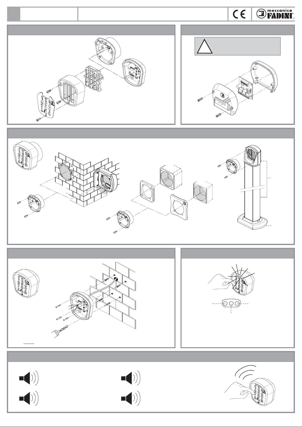
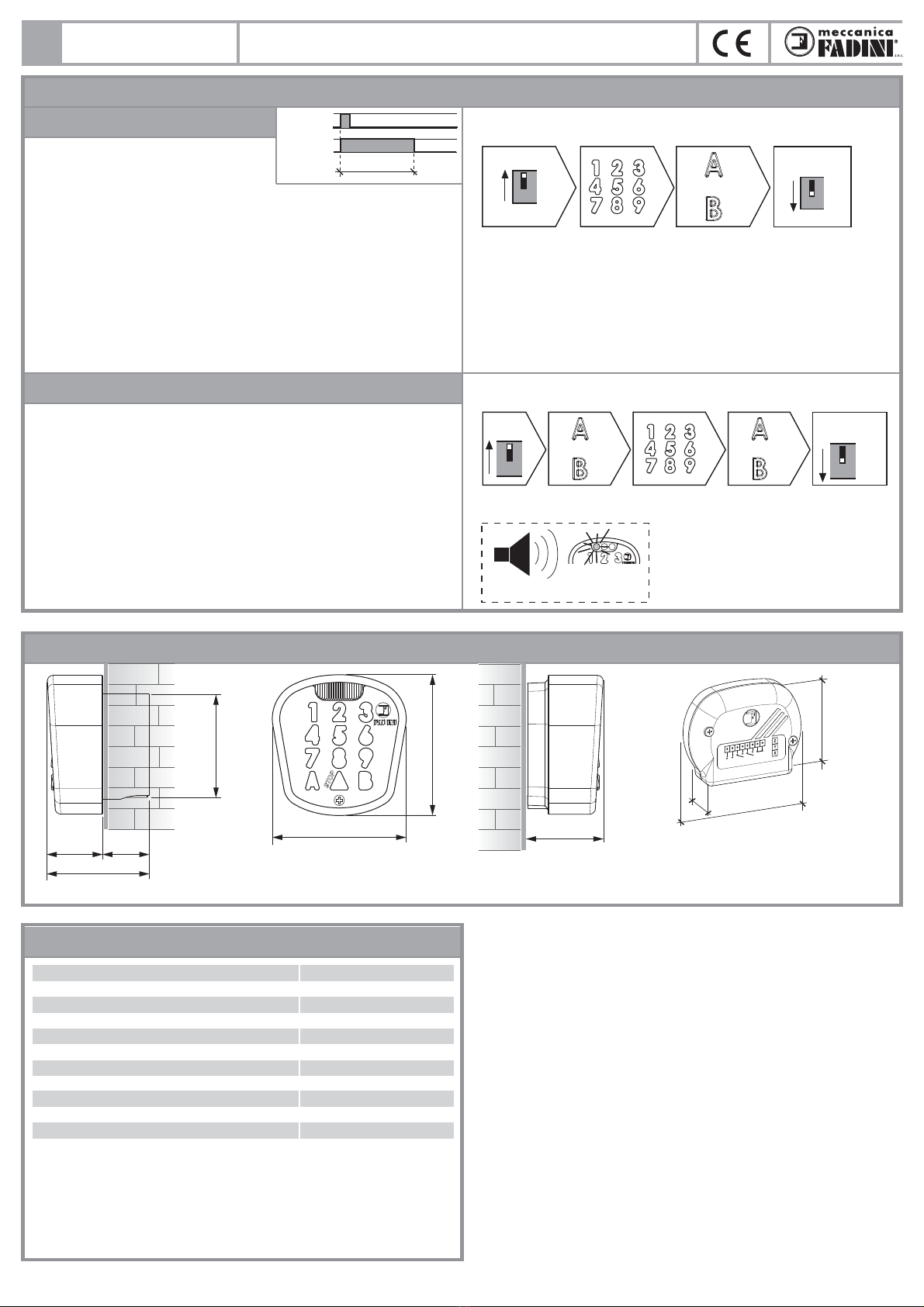
APERTURA DELLA TASTIERA APERTURA DELLA SCHEDINA MADRE
Coperchio in
alluminio
trattato
LED VERDE:
codice OK
LED BLU:
• luce ssa: - alimentazione presente
- identica in notturna
la posizione della tastiera
• luce intermittente: esecuzione di funzioni
temporizzate più professionali
LED ROSSO: codice
errato o pulsante di
STOP attivato
Mascherina
inox
Fondello da parete
in alluminio trattato
Fondello da incasso
in materiale plastico
Tastiera
DGT 61
12-24V
ac/dc
NC
cod. 612L
LUCI A LEDFISSAGGIO DELLA TASTIERA ALLA PARETE
DISPOSITIVO SONORO
ACCESSORI DI FISSAGGIO DELLA TASTIERA DA INCASSO
cod. 552L
cod. 560L
cod. 553L
Sech 15 cod. 557L
cod. 554L
Prit 19
cod. 611L
cod. 558L
cod. 610L
PULSANTIERA A CODICE DIGITALE
1
Bip: un segnale sonoro conferma
la corretta sequenza del codice
n°1 Bip breve: segnala l'avvenuta
pressione del pulsante sulla tastiera
n°3 Bip brevi: segnala una errata
sequenza del codice di accesso
n°5 Bip brevi: conferma la corretta operazione
di cancellazione della memoria
3
5
Fig. 2
Fig. 3
Fig. 1
Fig. 5
Fig. 6
Fig. 4
ATTENZIONE: questa schedina deve
essere installata in un luogo protetto
all'interno dell'ingresso da aprire.
!
istr_dgt61_I.ai 3 16/12/2020 16:48:26

I
La pulsantiera digitale DGT 61 è un accessorio di comando a codice personalizzato studiato per l'apertura e la chiusura di qualsiasi impianto automatizzato ed
inoltre per la gestione di altre utenze esterne. La DGT 61 è formata da una Tastiera (in un contenitore di alluminio trattato anticorrosione da ssare a parete
o ad incasso) collegata via cavo (n°4 li) alla Schedina Madre; quest'ultima da installare vicino al programmatore elettronico serie Elpro, per eseguirne i
collegamenti elettrici. La Tastiera si compone di una serie di pulsanti retroilluminati a luce blu: nove numeri, due uscite A e B e un'uscita di stop di emergenza.
La Schedina Madre dispone di una morsettiera per ricevere l'alimentazione esterna (in parallelo anche alle Tastiere), di contatti di uscita NA dei relè A e B e di
una uscita NC pulita di un terzo relè, per il collegamento di un eventuale stop di emergenza. Una seconda morsettiera per i contatti X e Y (con un terzo morsetto
Z per segnali lontani o disturbati) riceve il segnale di codica proveniente dalle Tastiere. La programmazione, semplice ed immediata, avviene tramite
i Dip-Switch posti sulla Schedina Madre. Si possono memorizzare per ciascun canale no ad un massimo di 4 codici numerici diversi; codici dierenti sullo
stesso canale A o B eseguono sempre la stessa codica e le stesse funzioni. Si possono applicare ai due relè altre funzioni più professionali (uscite bistabili,
bistabili temporizzate, ritardi di uscita, ecc), semplicemente abilitandole mediante Dip-Switch sulla Schedina Madre; è inoltre possibile gestire altre utenze
esterne (illuminazioni, allarmi, irrigazioni), aperture automatiche interne, ecc.
Si consiglia in questi casi di mettere sempre un relè tra la schedina madre e le altre eventuali utenze.
4
DESCRIZIONE GENERALE
SCHEMA DI UNA POSSIBILE INSTALLAZIONE CON 2 TASTIERE E UNA SCHEDINA MADRE
Fig. 7
Fig. 8
Led rosso 1:
lampeggia in fase
di programmazione
schedina madre
n°1 o più Tastiere
DGT 61
(*) il collegamento al
morsetto Z è necessario
in caso di un segnale
debole o disturbato
12-24V
ac/dc
12-24V
ac/dc
24V
ac/dc
12-24V
ac/dc
12-24V ac/dc STOP
max 0,5mm² no 100m
Led rosso 2:
lampeggia lento quando
c'è comunicazione XY con la tastiera
Ponte per alimentazione 12Vac:
a ponticello inserito è possibile
alimentare a 12Vac
XYZ
ABS
CNA NACNC
C
ON
OFF 12345678910 (*)
1**
ON
ON
3**
ON
4**
ON
2**
ON
ON
ON
ON
1**
2**
3**
4**
relè NA relè NA relè NC
= contatto pulito di STOP: solo come funzione
diretta al relè per funzione di emergenza
**nita la fase di memorizzazione posizionare in OFF tutti i Dip
ingresso
automatizzato B o
altre utenze
ingresso
automatizzato A o
altre utenze
1° CODICE
sul relè A
2° CODICE
sul relè A
3° CODICE
sul relè A
4° CODICE
sul relè A
Tastiera DGT 61 Programmatore serie
Elpro - Ingresso A
Programmatore serie
Elpro 6 - Ingresso B
Tastiera DGT 61
1° CODICE
sul relè B
2° CODICE
sul relè B
3° CODICE
sul relè B
4° CODICE
sul relè B
XYZ
12345678910
AB
CNA NACNCC
XYZ
3 4 6
XYZ
3 4
3
33
XYZ
S
ON
OFF
(*) (*)
(*)
DGT 61
12-24V
ac/dc
NC
apre
apre
stop
comune
apre
stop
24Vac/dc
comune
apre/blocco/chiude
schedina madre
relè NA relè NA relè NC
(*) il collegamento
al morsetto Z è
necessario
in caso di un segnale
debole o disturbato
max 0,5mm²
no 100m
0,5mm² no 100m
DGT 61 PULSANTIERA A CODICE DIGITALE
istr_dgt61_I.ai 4 16/12/2020 16:48:27
I
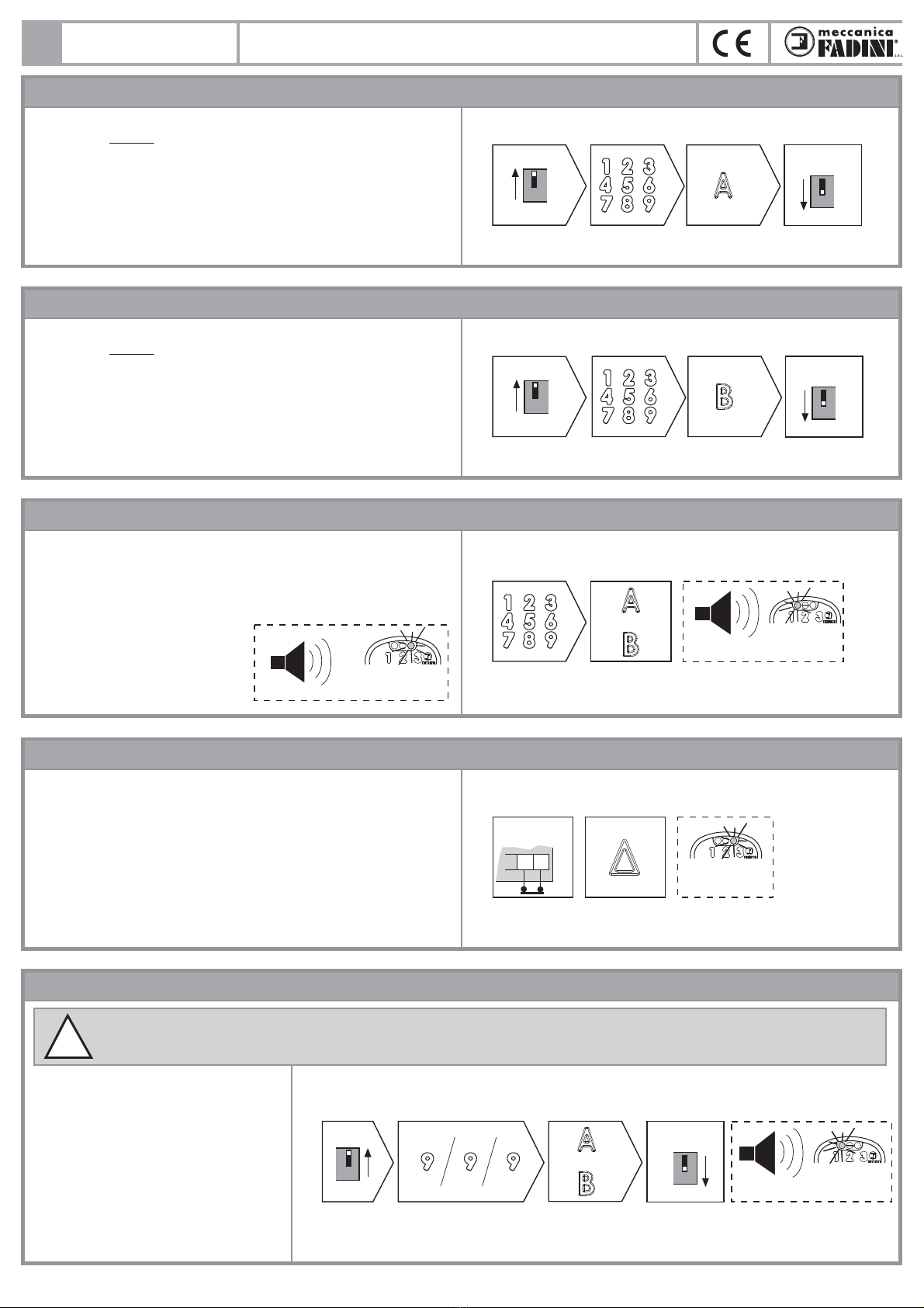
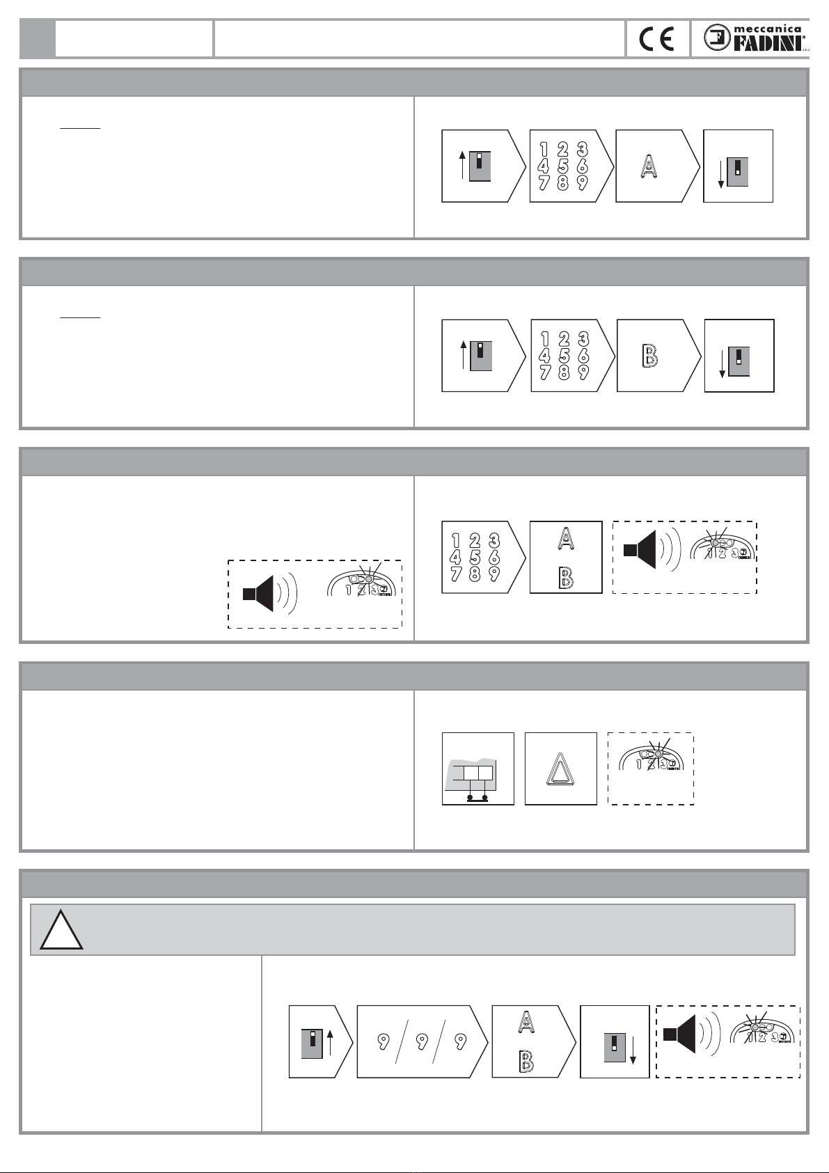
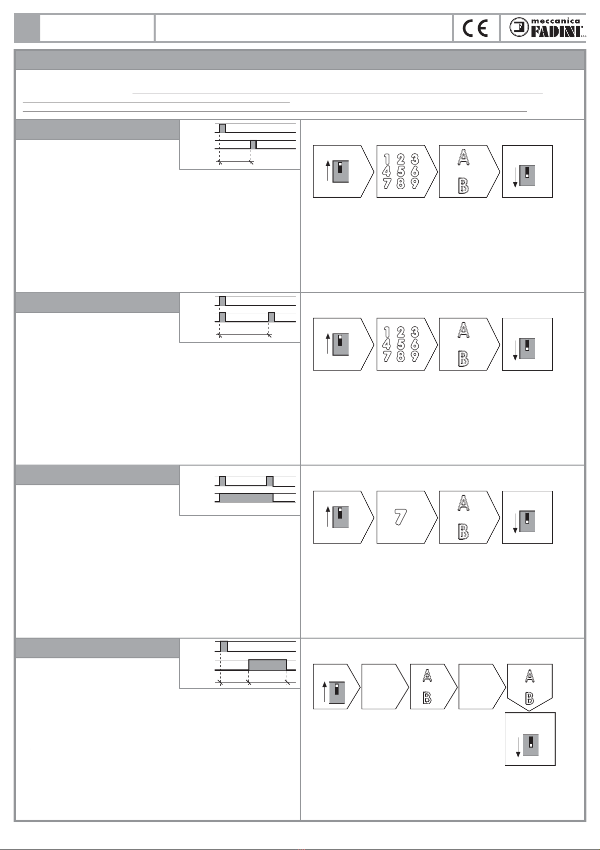
MEMORIZZARE UNO O PIÙ CODICI DI ACCESSO SULL'USCITA DEL RELÈ A
5
!ATTENZIONE: questa operazione cancella denitivamente ogni codice di accesso e tutte le funzioni aggiuntive memorizzate sul relè digitato
in questa procedura.
DGT 61 PULSANTIERA A CODICE DIGITALE
1) Eseguire i collegamenti elettrici della SCHEDINA MADRE (Fig.8).
2) Posizionare uno solo dei DIP 1 o DIP 2 o DIP 3 o DIP 4 in ON (i primi quattro
DIP permettono di memorizzare CODICI DI ACCESSO diversi).
Il led rosso 1 sulla schedina madre lampeggia.
3) Digitare il CODICE DI ACCESSO (da 1 a 6 numeri) - premere A.
Il led verde si accende seguito da un Bip lungo di conferma.
4) Posizionare tutti i DIP in OFF. Il led rosso 1 sulla schedina si spegne.
NOTA: sul relè A si possono inserire al massimo 4 codici diversi. Ogni codice
viene memorizzato singolarmente posizionando in ON uno dei primi 4 DIP.
OFF
1) 3) 4)
1
1
ON 2)
Schema riassuntivo
relè A
CODICE DI
ACCESSO
schedina
madre
TUTTI I DIP
IN OFF
schedina
madre
MEMORIZZARE UNO O PIÙ CODICI DI ACCESSO SULL'USCITA DEL RELÈ B
1) Eseguire i collegamenti elettrici della SCHEDINA MADRE (Fig.8).
2) Posizionare uno solo dei DIP 1 o DIP 2 o DIP 3 o DIP 4 in ON (i primi quattro
DIP permettono di memorizzare CODICI DI ACCESSO diversi).
Il led rosso 1 sulla schedina madre lampeggia.
3) Digitare il CODICE DI ACCESSO (da 1 a 6 numeri) - premere B.
Il led verde si accende seguito da un Bip lungo di conferma.
4) Posizionare tutti i DIP in OFF. Il led rosso 1 sulla schedina si spegne.
NOTA: sul relè B si possono inserire al massimo 4 codici diversi. Ogni codice
viene memorizzato singolarmente posizionando in ON uno dei primi 4 DIP.
FUNZIONAMENTO DELLA TASTIERA DGT 61
Eseguiti i collegamenti necessari tra la schedina madre e il programmatore
serie Elpro e successivamente memorizzati i CODICI DI ACCESSO sull'uscita,
per utilizzare la pulsantiera basterà solamente digitare il CODICE DI ACCESSO
seguito dall'USCITA che si vuole attivare (Aoppure B).
Il led verde si accende seguito da un Bip lungo di conferma.
Una errata sequenza del codice:
viene seguito da 3 bip con il led
rosso acceso per 2 secondi.
Ripetere la sequenza oppure
riprogrammare il codice. n°3 Bip brevi
3
led rosso
per 2 secondi
Schema riassuntivo
OFF
1) 3) 4)
1
1
ON 2)
relè B
CODICE DI
ACCESSO
schedina
madre
TUTTI I DIP
IN OFF
schedina
madre
1)
oppure
CODICE DI
ACCESSO
uscita A o B
Schema riassuntivo
2)
BIP led verde
per 1 secondo
ABILITARE IL PULSANTE DI STOP
Eseguire i collegamenti elettrici tra pulsantiera, schedina madre e programmatore
serie Elpro (o un relè di comando). Fig.8.
La schedina DGT 61 prevede anche un contatto pulito NC per la funzione di
STOP. Il contatto ai morsetti C - NC della schedina madre viene aperto all'impulso
diretto dal pulsante di STOP della pulsantiera senza bisogno di nessun
codice.
led rosso
per 2 secondi
schedina
madre
contatto pulito
per lo STOP
premere
STOP
Schema riassuntivo
NCC
S
CANCELLARE LA MEMORIA
1) Posizionare il Dip 10 in ON. Il led rosso 1
lampeggia.
2) Digitare sulla tastiera 9 9 9 (tre volte 9).
3) Premere il pulsante A oppure Bper
cancellare i codici e le funzoni
rispettivamente sull'uscita A oppure B.
4) Posizionare tutti i DIP in OFF.
A conferma 5 bip brevi e il led verde
lampeggia per la durata dei bip.
5
OFF
4)
10
schedina
madre
TUTTI I DIP
IN OFF
oppure
n°5 Bip led verde
Schema riassuntivo
schedina
madre
tastiera uscita A o B
1) 2) 3)
ON
10
istr_dgt61_I.ai 5 16/12/2020 16:48:27

I
6
OFF
1) 3) 4)
5
5
ON 2)
Schema riassuntivo
uscita A o B
tempo in minuti
(max 1439 = 24h)
schedina
madre
TUTTI I DIP
IN OFF
schedina
madre
oppure
FUNZIONI AGGIUNTIVE: si applicano alle uscite A e B già codicate con uno o più codici di accesso
RITARDO DI USCITA
Eseguire i collegamenti elettrici della schedina madre al programmatore (Fig.8) o al relè di comando esterno, quindi memorizzare un codice di accesso sulle
uscite desiderate. Le funzioni si possono applicare a una o ad entrambe le uscite, anche diverse tra loro, mentre codici diversi sul singolo relè eseguono
sempre la stessa funzione.
ATTENZIONE: in presenza di un black-out di alimentazione, le singole funzioni si resettano restando memorizzate sulla ricevente.
Programmazione:
1) Posizionare il DIP 5 in ON. Il led rosso 1 sulla schedina lampeggia.
2) Digitare il ritardo di attivazione in minuti (massimo 1439 minuti).
3) Premere l'uscita Aoppure Bsulla quale si vuole eseguire la funzione.
4) A conferma dell'operazione: un bip e il led verde acceso per 2 s.
5) Posizionare tutti i DIP in OFF.
Utilizzo della funzione:
Digitare il codice di accesso seguito dall'uscita Ao Bprogrammata.
Il led verde si accende per 1 s seguito da un bip di attivazione.
Il led blu comincia a lampeggiare indicando che la funzione è stata attivata.
Per RESETTARE (annullamento temporaneo della funzione) digitare:
Aoppure B- codice di accesso - A oppure B
Il led verde si accende per 1 s seguito da un bip di conferma, mentre il led
blu rimane acceso.
Tempo
comando
uscita
Viene emesso un impulso ritardato
(in minuti) dopo il codice.
OFF
1) 3) 4)
6
6
ON 2)
Schema riassuntivo
uscita A o B
tempo in minuti
(max 1439 = 24h)
schedina
madre
TUTTI I DIP
IN OFF
schedina
madre
oppure
TEMPORIZZATO A 2 IMPULSI
Programmazione:
1) Posizionare il DIP 6 in ON. Il led rosso 1 sulla schedina lampeggia.
2) Digitare il tempo in minuti dopo il primo impulso (massimo 1439 minuti).
3) Premere l'uscita Aoppure Bsulla quale si vuole eseguire la funzione.
4) A conferma dell'operazione: un bip e il led verde acceso per 2 s.
5) Posizionare tutti i DIP in OFF.
Utilizzo della funzione:
Digitare il codice di accesso seguito dall'uscita Ao Bprogrammata.
Il led verde si accende per 1 s seguito da un bip di attivazione.
Il led blu comincia a lampeggiare indicando che la funzione è stata attivata.
Per RESETTARE (annullamento temporaneo della funzione) digitare:
Aoppure B- codice di accesso - A oppure B
Il led verde si accende per 1 s seguito da un bip di conferma, mentre il led
blu rimane acceso.
Viene emesso un impulso dopo il
codice digitato e uno seguente dopo
un tempo (in minuti) programmato. Tempo
comando
uscita
RITARDO TEMPORIZZATO
Programmazione:
1) Posizionare il DIP 8 in ON. Il led rosso 1 lampeggia
2) Digitare il tempo 1 di ritardo in minuti (massimo 1439 minuti)
3) Premere l'uscita Aoppure Bsulla quale si vuole eseguire la funzione.
4) A conferma dell'operazione: un bip e il led verde acceso per 2 s.
5) Digitare il tempo 2 in minuti (massimo 1439 minuti).
6) Premere l'uscita Aoppure Bche si è premuto nel punto 3).
7) A conferma dell'operazione: un bip e il led verde acceso per 2 s.
8) Posizionare tutti i DIP in OFF.
Utilizzo della funzione:
Digitare il codice di accesso seguito dall'uscita Ao Bprogrammata.
Il led verde si accende per 1 s seguito da un bip di attivazione.
Il led blu comincia a lampeggiare indicando che la funzione è stata attivata.
Per RESETTARE (annullamento temporaneo della funzione) digitare:
Aoppure B- codice di accesso - A oppure B
Il led verde si accende per 1 s seguito da un bip di conferma, mentre il led
blu rimane acceso.
Ad ogni impulso del codice
digitato viene ritardata (in minuti)
l'attivazione del relè a tempo.
OFF
1) 3) 4)
7
7
ON 2)
Schema riassuntivo
uscita A o B
premere
il tasto 7
schedina
madre
TUTTI I DIP
IN OFF
schedina
madre
oppure
BISTABILE
Programmazione:
1) Posizionare il DIP 7 in ON. Il led rosso 1 sulla schedina lampeggia.
2) Premere solo il tasto 7.
3) Premere l'uscita Aoppure Bsulla quale si vuole eseguire la funzione.
4) A conferma dell'operazione: un bip e il led verde acceso per 2 s.
5) Posizionare tutti i DIP in OFF.
Utilizzo della funzione:
Digitare il codice di accesso seguito dall'uscita Ao Bprogrammata.
Il led verde si accende per 1 s seguito da un bip di attivazione.
Ad ogni impulso del codice digitato,
si attiva o disattiva il relè di uscita.
comando
uscita
TUTTI I DIP
IN OFF
Schema riassuntivo
schedina
madre
tastiera
tempo 1 in
minuti
(max 1439)
tempo 2 in
minuti
(max 1439)
uscita A o B tastiera
oppure oppure
1)
ON
8
2) 3)
OFF
8
4) 5)
6)
comando
uscita
Tempo 1 Tempo 2
DGT 61 PULSANTIERA A CODICE DIGITALE
istr_dgt61_I.ai 6 16/12/2020 16:48:28

7
I
Fig. 9
OFF
1) 3) 4)
9
9
ON 2)
Schema riassuntivo
uscita A o B
tempo in minuti
(max 1439 = 24h)
schedina
madre
TUTTI I DIP
IN OFF
schedina
madre
oppure
FUNZIONI AGGIUNTIVE: si applicano alle uscite A e B già codicate con uno o più codici di accesso
TEMPORIZZATO BISTABILE
Programmazione:
1) Posizionare il DIP 9 in ON. Il led rosso 1 sulla schedina lampeggia.
2) Digitare il tempo di attivazione in minuti (massimo 1439 minuti).
3) Premere l'uscita Aoppure Bsulla quale si vuole eseguire la funzione.
4) A conferma dell'operazione: un bip e il led verde acceso per 2 s.
5) Posizionare tutti i DIP in OFF.
Utilizzo della funzione:
Digitare il codice di accesso seguito dall'uscita Ao Bprogrammata.
Il led verde si accende per 1 s seguito da un bip di attivazione.
Il led blu comincia a lampeggiare indicando che la funzione è stata attivata.
Per RESETTARE (annullamento temporaneo della funzione) digitare:
Aoppure B- codice di accesso - A oppure B
Il led verde si accende per 1 s seguito da un bip di conferma, mentre il led
blu rimane acceso.
Tempo
comando
uscita
Attiva il relè e rimane attivato per
il tempo (in minuti) impostato.
CANCELLARE LE FUNZIONI AGGIUNTIVE
1) Posizionare il DIP 5 in ON. Il led rosso 1 sulla schedina lampeggia.
2) Premere A (oppure B) - codice di accesso - premere A (oppure B).
3) Premere l'uscita Aoppure Bsulla quale si vuole eseguire la funzione.
4) A conferma dell'operazione: un bip e il led verde acceso per 2 s.
5) Posizionare tutti i DIP in OFF.
Procedimento per annullare le funzioni aggiuntive sul singolo relè.
MISURE D'INGOMBRO
DATI TECNICI
DGT 61 PULSANTIERA A CODICE DIGITALE
BIP led verde
per 2 secondi
TUTTI I DIP
IN OFF
Schema riassuntivo
schedina
madre
schedina
madre
CODICE DI
ACCESSO
uscita A o B uscita A o B
oppure
1)
ON
5
2)
oppure
OFF
5
3)
DGT 61
12-24V
ac/dc
AB
NC
91
73
27
40
72 mm
29 25
54
Ø56 74
Tastiera da incasso
Tastiera Tastiera da
parete
Schedina
madre
Alimentazione 2x0,5 mm² 12-24 Vac/dc
Collegamenti alla tastiera 4 x 0,5 mm²
Assorbimento tastiera 15 mA
Assorbimento relè a riposo 4 mA
Assorbimento relè attivato 27 mA
Temperatura di lavoro -20 °C + 80 °C
Canali NA 2
Canali NC 1
Distanza di comunicazione max 100 m
Contatti di uscita 1 A - 120 V - 60 VA
Grado di protezione tastiera IP 54
Grado di protezione schedina IP 53
istr_dgt61_I.ai 7 16/12/2020 16:48:28
DIGITAL KEYPAD
DGT 61
GB
8
GENERAL WARNINGS FOR PEOPLE SAFETY
INTRODUCTION
This operator is designed for a specic scope of applications as
indicated in this manual, including safety, control and signaling
accessories as minimum required with FADINI equipment. □
Any applications not explicitly included in this manual may
cause operation problems or damages to properties and
people. □Meccanica Fadini snc is not liable for damages
caused by the incorrect use of the equipment, or for
applications not included in this manual or for malfunctioning
resulting from the use of materials or accessories not
recommended by the manufacturer. □The manufacturer
reserves the right to make changes to its products without
prior notice. □All that is not explicitly indicated in this manual
is to be considered not allowed.
BEFORE INSTALLATION
Before commencing operator installation assess the suitability
of the access, its general condition and the structure. □Make
sure that there is no risk of impact, crushing, shearing,
conveying, cutting, entangling and lifting situations, which
may prejudice people safety. □Do not install near any source of
heat and avoid contacts with ammable substances. □Keep all
the accessories able to turn on the operator (transmitters,
proximity readers, key-switches, etc) out of the reach of the
children. □Transit through the access only with stationary
operator. □Do not allow children and/or people to stand in the
proximity of a working operator. □To ensure safety in the
whole movement area of a gate it is advisable to install
photocells, sensitive edges, magnetic loops and detectors. □
Use yellow-black strips or proper signals to identify dangerous
spots. □Before cleaning and maintenance operations,
disconnect the appliance from the mains by switching o the
master switch. □If removing the actuator, do not cut the
electric wires, but disconnect them from the terminal box by
loosening the screws inside the junction box.
INSTALLATION
All installation operations must be performed by a qualied
technician, in observance of the Machinery Directive
2006/42/CE and safety regulations EN 12453 - EN 12445. □
Verify the presence of a thermal-magnetic circuit breaker
0,03 A - 230 V - 50 Hz upstream the installation. □Use
appropriate objects to test the correct functionality of the
safety accessories, such as photocells, sensitive edges, etc. □
Carry out a risk analysis by means of appropriate instruments
measuring the crushing and impact force of the main opening
and closing edge in compliance with EN 12445. □Identify the
appropriate solution necessary to eliminate and reduce such
risks. □In case where the gate to automate is equipped with a
pedestrian entrance, it is appropriate to prepare the system in
such a way to prohibit the operation of the engine when the
pedestrian entrance is used. □Apply safety nameplates with CE
marking on the gate warning about the presence of an
automated installation. □The installer must inform and instruct
the end user about the proper use of the system by releasing
him a technical dossier, including: layout and components of
the installation, risk analysis, verication of safety accessories,
verication of impact forces and reporting of residual risks.
INFORMATION FOR END-USERS
The end-user is required to read carefully and to receive
information concerning only the operation of the installation
so that he becomes himself responsible for the correct use of it.
□The end-user shall establish a written maintenance contract
with the installer/maintenance technician (on -call). □Any
maintenance operation must be done by qualied technicians.
□Keep these instructions carefully.
WARNINGS FOR THE CORRECT OPERATION OF THE
INSTALLATION
For optimum performance of system over time according to
safety regulations, it is necessary to perform proper
maintenance and monitoring of the entire installation: the
automation, the electronic equipment and the cables
connected to these.
□The entire installation must be carried out by qualied
technical personnel, lling in the Maintenance Manual
indicated in the Safety Regulation Book (to be requested or
downloaded from the site
www.fadini.net/supporto/downloads).
□Operator: maintenance inspection at least every 6 months,
while for the electronic equipment and safety systems an
inspection at least once every month is required. □The
manufacturer, Meccanica Fadini snc, is not responsible for
non-observance of good installation practice and incorrect
maintenance of the installation.
DISPOSAL OF MATERIALS
Dispose properly of the packaging materials such as
cardboard, nylon, polystyrene etc. through specializing
companies (after verication of the regulations in force at the
place of installation in the eld of waste disposal). Disposal of
electrical and electronic materials: to remove and dispose
through specializing companies, as per Directive 2012/19/UE.
Disposal of substances hazardous for the environment is
prohibited.
UE DECLARATION OF CONFORMITY (DoC)
Manufacturer: Meccanica Fadini snc
Address: Via Mantova, 177/A - 37053 Cerea - VR - Italy
declare that the DoC is issued under our sole responsibility and
belongs to the following product:
Digital Keypad DGT 61
is in conformity with the relevant Union harmonisation legislation:
- Electromagnetic Compatibility Directive 2014/30/UE
- Low Voltage Directive 2014/35/UE
Cerea, 19/04/2017 Meccanica Fadini s.n.c.
Responsible Manager
istr_dgt61_GB.ai 1 16/12/2020 16:48:55

GB
NOTE: screws and expanding bolts not supplied by us.
9
DGT 61
BRINGING THE KEYPAD APART BRINGING THE MAIN PCB APART
Treated aluminium
front unit
GREEN LED:
access code OK
BLUE LED:
• Fixed light: - unit on voltage
- night illumination of the keypad
• Flashing light: professionaly advanced timed
functions in progress
RED LED: wrong
access code
or STOP button
activated
Stainless steel
front cover
Treated aluminium
back casing
surface mount
Plastic back casing
recess mount
Keypad
DGT 61
12-24V
ac/dc
NC
code 612L
LED LIGHTSSURFACE APPLICATION OF THE KEYPAD TO A WALL
SOUND DEVICE
ACCESSORIES TO FIT THE KEYPAD, RECESS APPLICATION
code 552L
code 560L
code 553L
Sech 15 code 557L
code 554L
Prit 19
code 611L
code 558L
code 610L
1
Beep: a beep conrms the correct
access code sequence
n°1 short beep: is emitted whenever
a key button is pressed
n°3 short beeps: the access code
sequence is wrong
n°5 short beeps: memory clearing
carried out correctly
3
5
Pic. 2
Pic. 3
Pic. 1
Pic. 5
Pic. 6
Pic. 4
ATTENTION: This unit is
recommended to be installed in a
safe and sheltered place.
!
DIGITAL KEYPAD
istr_dgt61_GB.ai 2 16/12/2020 16:48:57

GB
DGT 61 is a custom-encoded control accessory designed to open and close any automatic access system. It can be also used to control other external applications.
DGT 61 consists of a Keypad (in an anti-corrosion treated aluminium casing, in two options either to be partially recessed or surface mounted) cable
connected (x 4 wires) to the Main PCB; this one is to be installed near the Elpro electronic control box for the electrical connections. The keypad incorporates
the button keys, illuminated in blue from the back: nine digits, two outputs A and B and one output for the emergency stop button. The main PCB is tted with a
terminal block where power supply is to be connected (in parallel also to the keypads), with the N.O. contacts of the A and B output relays and with one pure
N.C. terminal output of a third relay, providing connections for an emergency stop. A second block of terminals X and Y (and a third one Z for long distance or
disturbed signals) receive the encoded signal from the keypads. Programming is simple and immediate by Dip-switches on the main PCB. Each channel can
take up to 4 dierent numerical codes; any one code, through the same channel either A or B, operates the same function. Other professionally advanced
functions can be achieved by the two relays (bistable outputs, timed bistable outputs, output delay, etc.), and can be enabled by the Dip-switches on the main
PCB. Other external control applications are also made possible (eg. illumination, alarm systems and watering) besides automatic door/gate systems, etc.
In these cases, it is recommended that a relay be always tted between the PCB and the other possible applications.
10
GENERAL DESCRIPTION
DIAGRAM OF A POSSIBLE INSTALLATION WITH TWO KEYPADS AND ONE PCB
Pic. 7
Pic. 8
Red led 1:
It ashes during
programming phase
Main PCB
1 or more
keypads DGT 61
(*) the connection to the
Z terminal is required in
case of weak or
disturbed signal
12-24V
ac/dc
12-24V
ac/dc
24V
ac/dc
12-24V
ac/dc
12-24V ac/dc STOP
max 0,5mm² up to 100m
Red led 2:
It ashes slowly when X Y are
properly connected to the keypad
Jumper for 12Vdc power supply:
when jumper is tted, 12Vdc
power supply is possible
XYZ
ABS
CNO NOCNC
C
ON
OFF 12345678910 (*)
1**
ON
ON
3**
ON
4**
ON
2**
ON
ON
ON
ON
1**
2**
3**
4**
relay NO relay NO relay NC
= Pure contact for STOP function only: direct to
the relay in case of an emergency
**once encoding/programming phases are completed, all Dip-switches are to be set to OFF
Automated
access B or
other applications
Automated
access A or
other applications
1st CODE
to relay A
2nd CODE
to relay A
3rd CODE
to relay A
4th CODE
to relay A
Keypad DGT 61 Controll box series
Elpro - access A
Controll box
Elpro 6 - access B
Keypad DGT 61
1st CODE
to relay B
2nd CODE
to relay B
3rd CODE
to relay B
4th CODE
to relay B
XYZ
12345678910
AB
CNO NOCNCC
XYZ
3 4 6
XYZ
3 4
3
33
XYZ
S
ON
OFF
(*) (*)
(*)
DGT 61
12-24V
ac/dc
NC
open
open
stop
common
open
stop
24Vac/dc
common
open/stop/close
main PCB
relay NO relay NO relay NC
(*) The connection
to Z terminal is
required in case of
weak or disturbed
signal
max 0,5mm²
up to 100m
0,5mm² up to 100m
DGT 61 DIGITAL KEYPAD
istr_dgt61_GB.ai 3 16/12/2020 16:48:58
GB
STORING ONE OR MORE ACCESS CODES ONTO THE RELAY OUTPUT A
11
!PLEASE NOTE: this operation erases completely all the access codes and any additional functions stored with the relay involved in this process.
DGT 61
1) Carry out the electrical connections to the MAIN PCB (Pic.8).
2) Set only one of the switches DIP 1 or DIP 2 or DIP 3 or DIP 4 to ON (It is
through the rst four DIp-switches that dierent ACCESS CODES can be
stored). The red led 1 on the main PCB ashes.
3) Press the ACCESS CODE (from 1 to 6 digits) - press A.
The green led goes on followed by a long conrming beep.
4) Set all DIP-switches to OFF. The red led 1 on the PCB goes o.
NOTE: The relay A can take up to 4 dierent access codes max. Each code is
to be stored individually by setting any one of the rst 4 DIP-switches to ON.
OFF
1) 3) 4)
1
1
ON 2)
Diagram
relay A
ACCESS
CODE
main PCB
ALL DIP-SW.
TO OFF
main PCB
STORING ONE OR MORE ACCESS CODES ONTO THE RELAY OUTPUT B
1) Carry out the electrical connections to the MAIN PCB (Pic.8).
2) Set only one of the switches DIP 1 or DIP 2 or DIP 3 or DIP 4 to ON (It is
through the rst four DIp-switches that dierent ACCESS CODES can be
stored). The red led 1 on the main PCB ashes.
3) Press the ACCESS CODE (from 1 to 6 digits) - press B.
The green led goes on followed by a long conrming beep.
4) Set all DIP-switches to OFF. The red led 1 on the PCB goes o.
NOTE: The relay B can take up to 4 dierent access codes max. Each code is
to be stored individually by setting any one of the rst 4 DIP-switches to ON.
HOW TO OPERATE WITH DGT 61 KEYPAD
Once satised that the main PCB is properly connected to the Elpro control
box, and the selected ACCESS CODES stored with the required output, to operate
with the keypad just press the keys corresponding to the ACCESS CODE,
followed by the key corresponding to the required OUTPUT (Aor B).
The green led goes on followed a long conrming beeping.
If the access code sequence is
incorrect: the unit gives out 3
beeping souds and the red led
illuminates for 2 seconds. Dial
correctly or reprogram the unit. n°3 short beeps
3
Red led
for 2 seconds
Diagram
OFF
1) 3) 4)
1
1
ON 2)
relay B
ACCESS
CODE
main PCB
ALL DIP-SW.
TO OFF
main PCB
1)
or
ACCESS
CODE
A or B output
Diagram
2)
BEEP green led
for 1 second
ENABLING THE STOP BUTTON KEY
Carry out the electrical connections to the keypad, main PCB and the Elpro
control box (or to a control relay). Pic. 8.
The DGT 61 keypad incorporates also a pure NC contact to get the STOP function.
The contacts of the C - NC terminals on the main PCB are opened on
pulsing the STOP button in the keypad, and no code is required to be entered.
red led
for 2 seconds
main PCB
STOP
pure contact
press
STOP
Diagram
NCC
S
MEMORY CLEARING
1) Set the Dip-sw. 10 to ON. The red led 1
ashes.
2) Press the key 9 9 9 (three times).
3) Press button A or Bto erase the encoding
and the functions from output A or B
4) Set all the DIP-switches to OFF.
5 short beeps conrm the operation
while the green led keeps ashing as
long as beeping can be heard.
5
OFF
4)
10
main PCB
ALL DIP-SW.
TO OFF
or
n°5 Beeps green led
Diagram
main PCB keypad A or B output
1) 2) 3)
ON
10
DIGITAL KEYPAD
istr_dgt61_GB.ai 4 16/12/2020 16:48:58

GB
12
OFF
1) 3) 4)
5
5
ON 2)
Diagram
A or B output
time in minutes
(max 1439 = 24h)
main PCB
ALL DIP-SW.
TO OFF
main PCB
or
ADDITIONAL FUNCTIONS: can be achieved by the A and B outputs through one or more access codes
OUTPUT DELAY
Connect the main PCB to the control box (Pic. 8) or to the external control relay, then store an access code with required outputs.
Dierent functions can be achieved by one or both of the outputs, but dierent access codes to one relay carry out the same function.
NOTE WELL: in the presence of a power black-out, the individual functions are reset and remain stored on the receiver.
Programming:
1) Set DIP-sw. 5 to ON. The red led 1 on the PCB ashes.
2) Press the number of minutes corresponding to the activation delay as
required (max.1439 minutes).
3) Press output Aor Bthrough which the required function is activated.
4) Conrmation of the operation: beep and green led alight for 2 s.
5) Set all the DIP-switches to OFF.
Using the function:
Press the access code followed by Aor Bas programmed. The green led goes on
for 1 s followed by an activation beep. The blue led starts ashing and indicates
that the function has been activated.
In order to RESET (temporary cancellation of the function) press the following
sequence:
Aor B- access code - A or B
The green led goes on for 1 s followed by a conrmation beep, while the
blue led stays illuminated.
Time
pulse
output
pulse
output
pulse
output
pulse
output
The pulse is delayed (for a number
of minutes) after pressing the access
code.
OFF
1) 3) 4)
6
6
ON 2)
Diagram
A or B output
time in minutes
(max 1439 = 24h)
main PCB
ALL DIP-SW.
TO OFF
main PCB
or
TIMED WITH 2 PULSES
Programming:
1) Set DIP-sw. 6 to ON. The red led 1 on the PCB ashes.
2) Press the number of minutes for the time required after the rst pulse
(max. 1439 minutes).
3) Press either Aor Boutput by which the function is to be activated.
4) Conrmation of the operation: beep and green led alight for 2 s.
5) Set all the DIP-switches to OFF.
Using the function:
Press the access code followed by Aor Bas programmed. The green led goes on
for 1 s followed by an activation beep. The blue led starts ashing and indicates
that the function has been activated.
In order to RESET (temporary cancellation of the function) press the following
sequence:
Aor B- access code - A or B
The green led goes on for 1 s followed by a conrmation beep, while the
blue led stays illuminated.
A pulse is given after the access code
has been pressed and another one is
given after a set time (minutes). Time
TIMED DELAY
Programming:
1) Set DIP-sw. 8 to ON. The red led 1 ashes.
2) Press the number of minutes for the delay with time 1 (max 1439 minutes).
3) Press either Aor Boutput by which the required function is to be activated.
4) Conrmation of the operation: beep and green led alight for 2 s.
5) Press the numer of minutes for time 2 (max. 1439 minutes).
6) Press ether Aor Bas set in step 3).
7) Conrmation of the operation: beep and green led alight for 2 s.
8) Set all the DIP-switches to OFF.
Using the function:
Press the access code followed by Aor Bas programmed.
The green led goes on for 1 s followed by an activation beep.
The blue led starts ashing and indicates that the function has been activated.
In order to RESET (temporary cancellation of the function) press the following
sequence:
Aor B- access code - A or B
The green led goes on for 1 s followed by a conrmation beep, while the
blue led stays illuminated.
Each pulse by the access code
delays (for a number of minutes)
the energizing of the timed relay.
OFF
1) 3) 4)
7
7
ON 2)
Diagram
A or B output
press key 7 main PCB
ALL DIP-SW.
TO OFF
main PCB
or
BISTABLE
Programming:
1) Set DIP-sw. 7 to ON. The red led 1 on the PCB ashes.
2) Press only the button key No. 7.
3) Press either Aor Boutput by which the required function is to be actived.
4) Conrmation of the operation: beep and green led alight for 2 s.
5) Set all the DIP-switches to OFF.
Using the function:
Press the access code followed by Aor Bas programmed.
The green led goes on for 1 s followed by an activation beeping.
Each pulse by the access code energizes or
de-energizes the output relay.
ALL DIP-SW.
TO OFF
Diagram
main PCB keypad
time 1 in
minutes
(max 1439)
time 2 in
minutes
(max 1439)
A or B output keypad
or or
1)
ON
8
2) 3)
OFF
8
4) 5)
6)
Time 1 Time 2
DGT 61 DIGITAL KEYPAD
istr_dgt61_GB.ai 5 16/12/2020 16:48:58
13
GB
Pic. 9
A or B output
A or B outputA or B output
pulse
output
OFF
1) 3) 4)
9
9
ON 2)
Diagram
time in minutes
(max 1439 = 24h)
main PCB
ALL DIP-SW.
TO OFF
main PCB
or
ADDITIONAL FUNCTIONS: can be achieved by the A and B outputs through one or more access codes
TIMED BISTABLE
Programming:
1) Set DIP-sw. 9 to ON. The red led 1 on the PCB ashes.
2) Press the number of minutes corresponding to the activation time as
required (max. 1439 minutes).
3) Press output A or B as required for the function to be activated.
4) Conrmation of the operation: beep and green led alight for 2 s.
5) Set all the DIP-switches to OFF.
Using the function:
Press the access code followed by Aor Bas programmed.
The green led goes on for 1 s followed by an activation beep.
The blue led starts ashing and indicates that the function has been activated.
In order to RESET (temporary cancellation of the function) press the following
sequence:
Aor B- access code - A or B
The green led goes on for 1 s followed by a conrmation beep, while the
blue led stays illuminated.
Time
The relay is energized and remain
energized for the time as set (in minutes).
REMOVING THE ADDITIONAL FUNCTIONS
1) Set DIP-sw. 5 to ON. The red led 1 on the PCB ashes.
2) Press A (or B) - access code - press A (or B).
3) Press either Aor Boutput by which the required function is to be activated.
4) Conrmation of the operation: beep and green led alight for 2 s.
5) Set all the DIP-switches to OFF.
Steps to cancel the additional functions from the single relay.
OVERALL DIMENSIONS
TECHNICAL DATA
DGT 61
BEEP gree led
for 2 seconds
ALL DIP-SW.
TO OFF
Diagram
main PCB main PCBACCESS
CODE
or
1)
ON
5
2)
or
OFF
5
3)
DGT 61
12-24V
ac/dc
AB
NC
91
73
27
40
29 25
54
Ø56
Recess mount keypad
Keypad Surface mount
keypad
Main
PCB
Power supply 2x0,5 mm² 12-24 Vac/dc
Connections to the keypad 4 x 0,5 mm²
Keypad absorption 15 mA
Stand-by relay absorption 4 mA
Energized relay absorption 27 mA
Working temperature -20 °C + 80 °C
N.O. channels 2
N.C. channels 1
Communication distance max 100 m
Output contacts 1 A - 120 V - 60 VA
Keypad protection standards IP 54
PCB protection standards IP 53
DIGITAL KEYPAD
72 mm
74
istr_dgt61_GB.ai 6 16/12/2020 16:48:59
CLAVIER CODE DIGITAL
DGT 61
F
14
AVERTISSEMENTS DE SECURITE AUX USAGERS
INTRODUCTION
Cet automatisme a été conçu pour une utilisation qui respecte ce
qu'il y a indiqué dans ce livret, avec les accessoires de sécurité et de
signalisation minimaux demandés et avec les dispositifs FADINI. □
Toute autre application pas expressément indiquée dans ce livret
pourrait provoquer des dysfonctionnements ou des dommages à
choses et personnes. □Meccanica Fadini n'est pas responsable
d'éventuels dommages provoqués par une utilisation impropre et
non spéciquement indiquée dans ce livret. En outre, elle n'est pas
responsable des dysfonctionnements causés de l'usage de
matériels ou accessoires non recommandés par le fabricant. □
L'entreprise de construction se réserve le droit d'apporter des
modications aux propres produits sans préavis. □Tout ce qui n'est
pas prévue dans cette notice d'installation n'est pas permis.
INSTRUCTIONS A SUIVRE AVANT L'INSTALLATION
Contrôler avant toute intervention que l'entrée soit adapté à
l'automatisation, ainsi que ces conditions et structure. □
Assurez-vous qu'y ne soit pas des risques d'impact, écrasement,
cisaillement, convoyage, entraînement et enlèvement, tells qu'on
pourrait aecter la sécurité des personnes. □Installer
l'automatisme loin de tout sources de chaleur et éviter le contact
avec substances inammables. □Garder tout dispositifs de
contrôle automatisme (émetteurs, lecteurs de proximité,
sélecteurs etc) hors de la portée des enfants. □Transiter à travers la
zone du mouvement du portail seulement lorsque l'automatisme
est fermé. □An de garantir un niveau de sécurité adéquat de
l'installation il est nécessaire d'utiliser photocellules, listeaux
sensibles, spires magnétiques, détecteurs de masse métalliques,
en assurant la sécurité de tout l'aire de mouvement du portail. □
Identier les points dangereux de l'installation en l'en indiquant
avec bandes jaune-noir ou autres signaux appropriés. □Couper
l'alimentation avant toute intervention d'entretien ou nettoyage
de l'installation. □Dans le cas on doit enlever l’opérateur du
portail, ne pas couper les ls électrique; mais les débrancher en
desserrant les vis du bornier.
L'INSTALLATION
Toute l'installation doit être accomplie par personnel technique
qualié et autorisé, conformément à la directive Machines
2006/42/CE et, notamment, aux normes EN 12445 et EN 12453. □
Vérier la présence en amont de l'installation d'un interrupteur
diérentiel magnétothermique de 0,03 A de courant 230 V - 50 Hz.
□Utiliser des objets approprié pour eectuer les tests de
fonctionnement des photocellules, détecteurs des masses
métalliques, listeaux sensibles, etc. □Eectuer une analyse des
risques, en utilisant instruments de détection de l'impact et
écrasement du bord principale d’ouverture et fermeture,
conformément aux normes EN 12445. □Dénir les solutions
appropriées pour éliminer ou réduire tels risques. □Dans le cas où
le portail à automatiser aurait doué d'une entrée piétonne, il serait
bon d'accomplir l'installation de façon que le moteur ne
fonctionne pas lorsque l'entrée piéton est utilisé. □Fournir des
indications concernant la position de l’installation en appliquant
sur le portail des plaquettes de signalisation marquée CE. □
L'installateur doit informer l'utilisateur sur le fonctionnement
correct du système, en lui remettant le dossier technique signé,
incluant: le schéma et les éléments composants l'installation,
l'analyse des risques, la vérication des accessoires de sécurité, la
vérication de la force d'impact et la déclaration des risques
résiduels.
INDICATIONS POUR L'UTILISATEUR FINAL
L'utilisateur doit consulter et recevoir information relative au
fonctionnement de l'installation et il devient lui-même
responsable du bon usage du système.
□Il faut qu'il conclue un contrat d'entretien ordinaire et
extraordinaire (sur appel) avec l'installateur/réparateur. □Toute
l’intervention d'entretien doivent être accompli par des
techniciens qualiés. □Conserver toujours la notice d'installation.
AVERTISSEMENTS POUR LE FONCTIONNEMENT CORRECT DE
L'INSTALLATION
Pour que l’installation fonctionne correctement de façon durable
et conformément aux normes de sécurité en vigueur, vous devez
faire eectuer un entretien correct et le monitorage de toute
l’installation au niveau de l’automation, des appareils
électroniques installés et des câblages qui y sont branchés. □
Toute l'installation doit être eectuée par un technicien qualié,
qui doit remplir le Manuel d'Entretien indiqué dans le Livret des
Normes (à demander ou télécharger sur le site
www.fadini.net/supporto/downloads). □L'automation: contrôle
d'entretien tous les 6 mois au moins, tandis que le contrôle
d'entretien des appareils électroniques et systèmes de sécurité
doit être accompli une fois par mois au moins. □Meccanica Fadini
snc n'est pas responsable de l'éventuel non-respect des règles de
bonne technique d'installation et/ou de l'entretien incorrect du
système.
RAMASSAGE DES MATERIAUX
Les éléments d'emballage, tels que le carton, nylon, polystyrène,
etc. peuvent être recyclés avec le collecte séparé (en vériant la
réglementation en vigueur en la matière dans le pays où le
dispositif est monté). Les composants électriques et
électroniques, les batteries peuvent contenir des substances
polluantes: enlever et coner tels composants aux sociétés
chargées du traitement et de l’élimination des déchets, dans le
respect de la directive 2012/19/UE. Ne pas jeter déchets nuisibles
à l'environnement.
Meccanica Fadini s.n.c.
Directeur Responsable
DECLARATION UE DE CONFORMITE
Fabricant: Meccanica Fadini snc
Adresse: Via Mantova, 177/A - 37053 Cerea - VR - Italy
déclare sous sa propre responsabilité que le produit:
Clavier codé digital DGT 61
il est conforme à la législation d'harmonisation de l'Union:
- Directive Compatibilité Electromagnétique 2014/30/UE
- Directive Basse Tension 2014/35/UE
Cerea, 19/04/2017
istr_dgt61_F.ai 1 16/12/2020 16:49:29

F
NOTE: les vis et les tasseaux gurés ici ne sont pas fournis.
15
DGT 61
OUVERTURE DU CLAVIER OUVERTURE DE LA CARTE MERE
Couvercle en
aluminium traité
LED VERTE:
code correct
LED BLEUE:
• Lumière xe: - alimentation présente
- identie la position du clavier
pendant la nuit
• Lumière clignotante: exécution des fonctions
temporisées plus professionnelles
LED ROUGE: code
incorrect ou touche
de STOP activée
Plaquette
inox
Boîte en aluminium
traité en saillie
Boîte en plastique
encastrable
Touches
DGT 61
12-24V
ac/dc
NC
cod. 612L
VOYANTS A LEDFIXATION DU CLAVIER AU MUR
DISPOSITIF SONORE
ACCESSOIRES DE FIXATION DU CLAVIER ENCASTRABLE
cod. 552L
cod. 560L
cod. 553L
Sech 15 cod. 557L
cod. 554L
Prit 19
cod. 611L
cod. 558L
cod. 610L
1
Bip: un signal sonore conrme la
correcte séquence du code
n°1 Bip bref: signale la pression de
la touche sur le clavier
n°3 Bips brefs: signale une séquence
incorrecte du code d'accès
n°5 Bips brefs: conrme la correcte opération
d'éacement de la mémoire
3
5
Fig. 2
Fig. 3
Fig. 1
Fig. 5
Fig. 6
Fig. 4
ATTENTION: Cette carte doit être
installée dans un lieu protegé à
l'intérieur de l'entrée à ouvrir.
!
CLAVIER CODE DIGITAL
istr_dgt61_F.ai 2 16/12/2020 16:49:31

F
Le clavier digital DGT 61 est un accessoire de commande à code personnalisé étudié pour l'ouverture et la fermeture de toutes les installations automatisées et
pour la gestion d'autres usagers externes. Le DGT 61 est un Clavier (contenu dans une boîte en aluminium traité anticorrosion à xer en saillie ou encastrable),
raccordé par câble (n°4 ls) à la Carte Mère, qui doit être installée près du programmateur électronique série Elpro, pour l'exécution des raccordements électriques.
Le Clavier est composé d'une série de touches rétroéclairées d'une lumière bleue: neuf chires, deux sorties A et B et une sortie de stop d'urgence.
La Carte Mère a un bornier pour recevoir l'alimentation externe (en parallèle aussi aux Claviers), elle a des contacts de sortie NO des relais A et B et une sortie
NF propre d'un troisième relais, pour le raccordement d'un possible stop d'urgence. Un deuxième bornier pour les contacts X et Y (avec une troisième borne Z
pour signaux lontains ou brouillés) reçoit le signal de codication provenant des Claviers. La programmation est simple et immédiate à travers les Dips-Switch
sur la Carte Mère. Sur chaque canal, on peut mémoriser jusqu'à un maximum de 4 codes numériques diérents; codes diérents sur le même canal A ou B
exécutent toujours le même codage et les mêmes fonctions. On peut appliquer aux deux relais d'autres fonctions plus professionnelles (sorties bistables,
bistables témporisées, retard de sortie, ecc), en les rendant habiles simplement à travers le Dip-Switch sur la Carte Mère. En outre on peut contrôler d'autres
usagers externes (illumination, alarmes, irrigation) et ouvertures automatiques internes, ecc.
En ce cas, on conseille de mettre toujours un relais entre la carte mère et les autres possibles usagers.
16
DESCRIPTION GENERALE
SCHEMA D'UNE POSSIBLE INSTALLATION AVEC 2 CLAVIERS ET UNE CARTE MERE
Fig. 7
Fig. 8
Led rouge 1:
clignote en phase
de programmation
carte mère
n°1 ou plus
Claviers DGT 61
(*) le raccordement
à la borne Z est nécessaire
en cas de signal faible
ou brouillé
12-24V
ac/dc
12-24V
ac/dc
24V
ac/dc
12-24V
ac/dc
12-24V ac/dc STOP
max 0,5mm² jusqu'à 100m
Led rouge 2:
clignote lentement quand il y a
communication XY avec le clavier
Pontage pour alimentation 12Vdc:
avec le pontage on peut
alimenter à 12Vdc
XYZ
ABS
CNO NOCNF
C
ON
OFF 12345678910 (*)
1**
ON
ON
3**
ON
4**
ON
2**
ON
ON
ON
ON
1**
2**
3**
4**
relais
NO
relais
NO
relais
NF
= contact propre de STOP: seulement comme
fonction directe au relais en cas d'urgence
**positionner sur OFF tous les dips-switch à la n de la phase de mémorisation
entrée automatisée B
ou usagers diérents
entrée automatisée A
ou usagers diérents
1° CODE
sur relais A
2° CODE
sur relais A
3° CODE
sur relais A
4° CODE
sur relais A
Clavier DGT 61 programmateur de série
Elpro - entrée A
programmateur
Elpro 6 - entrée B
Clavier DGT 61
1° CODE
sur relais B
2° CODE
sur relais B
3° CODE
sur relais B
4° CODE
sur relais B
XYZ
12345678910
AB
CNO NOCNFC
XYZ
3 4 6
XYZ
3 4
3
33
XYZ
S
ON
OFF
(*) (*)
(*)
DGT 61
12-24V
ac/dc
NC
ouvre
ouvre
stop
commun
ouvre
stop
24Vac/dc
commun
ouvre/arrêt/ferme
carte mère
(*) le raccordement
à la borne Z est
nécessaire en cas
d'un signal faible ou
brouillé
max 0,5mm²
jusqu'à100m
0,5mm² jusqu'à 100m
DGT 61 CLAVIER CODE DIGITAL
relais
NO
relais
NO
relais
NF
istr_dgt61_F.ai 3 16/12/2020 16:49:32

F
MEMORISER UN OU PLUSIEURS CODES D'ACCES SUR LA SORTIE DU RELAIS A
17
!ATTENTION: cette operation eace denitivement tous les codes d'acces et toutes les fonctions additionnelles memorisees sur le relais tape
pendant cette procedure.
DGT 61
1) Exécutez les raccordements électriques de la CARTE MERE (Fig.8).
2) Positionnez seulement un des DIP 1 ou DIP 2 ou DIP 3 ou DIP 4 sur ON (les
prémiers quatre DIPS permettent la mémorisation des CODES D'ACCES
diérents). La led rouge 1 sur la carte mère clignote.
3) Tapez le CODE D'ACCES (de 1 à 6 chires) - tapez A.
La led verte s'allume suivie d'un Bip long de conrmation.
4) Positionnez tous les DIPS sur OFF. Sur la carte, la led rouge 1 s'éteint. OFF
1) 3) 4)
1
1
ON 2)
Schéma récapitulatif
relais A
CODE
D'ACCES
carte mère
TOUS LES
DIPS SUR OFF
carte mère
MEMORISER UN OU PLUSIEURS CODES D'ACCES SUR LA SORTIE DU RELAIS B
NOTE: sur le relais A on peut introduire 4 codes diérents au maximum. Chaque
code est mémorisé individuellement en positionnant sur ON un des prémiers
4 DIPS.
1) Exécutez les raccordements électriques de la CARTE MERE (Fig.8).
2) Positionnez seulement un des DIP 1 ou DIP 2 ou DIP 3 ou DIP 4 sur ON (les
prémiers quatre DIPS permettent la mémorisation des CODES D'ACCES
diérents). La led rouge 1 sur la carte mère clignote.
3) Tapez le CODE D'ACCES (de 1 à 6 chires) - tapez B.
La led verte s'allume suivie d'un Bip long de conrmation.
4) Positionnez tous les DIPS sur OFF. Sur la carte, la led rouge 1 s'éteint.
NOTE: sur le relais A on peut introduire 4 codes diérents au maximum. Chaque
code est mémorisé individuellement en positionnant sur ON un des prémiers
4 DIPS.
FONCTIONNEMENT DU CLAVIER DGT 61
An d'utiliser le clavier, après l'exécution des raccordements nécessaires entre
la carte mère et le programmateur série Elpro et la mémorisation succéssive
des CODES D'ACCES sur la sortie, il faudra seulement taper le CODE D'ACCES
suivi de la SORTIE qu'on veut activer (Aou B).
La led verte s'allume suivie d'un Bip long de conrmation.
Une séquence incorrecte du
code: elle est suivie de 3 bips
avec la led rouge allumée pour 2
secondes. Répeter la séquence
ou réprogrammer le code. n°3 Bips brefs
3
led rouge
pour 2 secondes
Schéma récapitulatif
OFF
1) 3) 4)
1
1
ON 2)
relais B
CODE
D'ACCES
carte mère
TOUS LES
DIPS SUR OFF
carte mère
1)
ou
CODE
D'ACCES
sortie A ou B
Schéma récapitulatif
2)
BIP led verte
pour 1 seconde
HABILITER LA TOUCHE DE STOP
Exécutez les raccordements électriques parmi le clavier, la carte mère et le
programmateur série Elpro (ou un relais de commande). Fig.8.
La carte DGT 61 prévoit aussi un contact propre NF pour la fonction de STOP.
Le contact aux bornes C - NF de la carte mère est ouvert à l'impulsion directe
de la touche de STOP du clavier sans l'utilisation d'aucun code.
led rouge
pour 2 secondes
carte mère
contact propre
pour le STOP
taper
STOP
Schéma récapitulatif
NFC
S
EFFACER LA MEMOIRE
1) Positionnez le Dip 10 sur ON. La led rouge 1
clignote.
2) Tapez sur le clavier 9 9 9 (trois fois 9).
3) Tapez la touche A ou Bpour eacer les
codes et les fonctions respectivement sur la
sortie A ou B
4) Positionnez tous les DIPS sur OFF.
L'eacement est conrmé par 5 brefs bips
et par le clignotement de la led verte
pour la durée des bips.
5
OFF
4)
10
carte mère
TOUS LES
DIPS SUR OFF
ou
n°5 Bips led verte
Schéma récapitulatif
carte mère touches sortie A ou B
1) 2) 3)
ON
10
CLAVIER CODE DIGITAL
istr_dgt61_F.ai 4 16/12/2020 16:49:32
F
18
OFF
1) 3) 4)
5
5
ON 2)
Schéma récapitulatif
sortie A ou B
temps en minutes
(max 1439 = 24h)
carte mère
TOUS LES
DIPS SUR OFF
carte mère
ou
FONCTIONS ADDITIONNELLES: elles s'appliquent aux sorties A et B déjà codiées avec un ou plusieurs codes d'accès
RETARD DE SORTIE
Exécutez les raccordements électriques de la carte mère sur le programmateur (Fig.8) ou sur le relais de commande externe, ensuite mémorisez un code
d'accès sur les sorties choisies. Les fonctions peuvent être appliquées à une ou à toutes les deux sorties, même si elles sont diérentes entre eux, alors que
les codes diérents sur un relais individuel exécutent toujours la même fonction.
ATTENTION: en cas de coupure de l'alimentation électrique, les diérentes fonctions sont réinitialisées et restent enregistrées sur le récepteur.
Programmation:
1) Positionnez le DIP 5 sur ON. Sur la carte, la led rouge 1 clignote.
2) Tapez le retard d'activation en minutes (1439 minutes au maximum).
3) Tapez la sortie Aou Bsur laquelle on veut exécuter la fonction.
4) A conrmation de l'opération: un bip et la led verte allumée pour 2 s.
5) Positionnez tous les DIPS sur OFF.
Utilisation de cette fonction:
Tapez le code d'accès suivi de la sortie Aou Bprogrammée. La led verte s'allume
pour 1 s suivie d'un bip d'activation. La led bleue commence à clignoter en indiquant
que la fonction est active.
Pour METTRE A ZERO (annulation temporaire de la fonction) tapez:
Aou B - code d'accès - A ou B
La led verte s'allume pour 1s suivie d'un bip de conrmation, alors que la
led bleue reste allumée.
Temps
commande
sortie
commande
sortie
commande
sortie
commande
sortie
Il émet une impulsion retardée
(en minutes) après le code.
OFF
1) 3) 4)
6
6
ON 2)
Schéma récapitulatif
sortie A ou B
temps en minutes
(max 1439 = 24h)
carte mère
TOUS LES
DIPS SUR OFF
carte mère
ou
TEMPORISE A 2 IMPULSIONS
Programmation:
1) Positionnez le DIP 6 sur ON. Sur la carte, la led rouge 1 clignote.
2) Tapez le temps en minutes après la première impulsion (1439 min. au max).
3) Tapez la sortie Aou Bsur laquelle on veut exécuter la fonction.
4) A conrmation de l'opération: un bip et la led verte allumée pour 2 s.
5) Positionnez tous les DIPS sur OFF.
Utilisation de cette fonction:
Tapez le code d'accès suivi de la sortie Aou Bprogrammée. La led verte s'allume
pour 1 s suivie d'un bip d'activation. La led bleue commence à clignoter en indiquant
que la fonction est active.
Pour METTRE A ZERO (annulation temporaire de la fonction) tapez:
Aou B - code d'accès - A ou B
La led verte s'allume pour 1s suivie d'un bip de conrmation, alors que la
led bleue reste allumée.
Il émet une impulsion après le
code tapé et un autre signal après
un temps (en minutes) établi. Temps
RETARD TEMPORISE
Programmation:
1) Positionnez le DIP 8 sur ON. La led rouge 1 clignote.
2) Tapez le temps 1 de retard en minutes (1439 minutes au max).
3) Tapez la sortie Aou Bsur laquelle on veut exécuter la fonction.
4) A conrmation de l'opération: un bip et la led verte allumée pour 2 s.
5) Tapez le temps 2 en minutes (1439 minutes au max).
6) Tapez la sortie Aou Bqu'on a tapé au point 3).
7) A conrmation de l'opération: un bip et la led verte allumée pour 2 s.
8) Positionnez tous les DIPS sur OFF
Utilisation de cette fonction:
Tapez le code d'accès suivie de la sortie programmée Aou B. La led verte
s'allume pour 1 s suivie d'un bip d'activation. La led bleue commence à
clignoter en indiquant que la fonction est active.
Pour METTRE A ZERO (annulation temporaire de la fonction) tapez:
Aou B - code d'accès - A ou B
La led verte s'allume pour 1 s suivie d'un bip de conrmation, alors que la
led bleue reste allumée.
A chaque impulsion du code tapé,
l'activation du relais temporisateur
est retardée (en minutes).
OFF
1) 3) 4)
7
7
ON 2)
Schéma récapitulatif
sortie A ou B
tapez la touche 7 carte mère
TOUS LES
DIPS SUR OFF
carte mère
ou
BISTABLE
Programmation:
1) Positionnez le DIP 7 sur ON. Sur la carte, la led rouge 1 clignote.
2) Tapez seulement la touche 7.
3) Tapez la sortie Aou Bsur laquelle on veut exécuter la fonction.
4) A conrmation de l'opération: un bip et la led verte allumée pour 2 s.
5) Positionnez tous les DIPS sur OFF.
Utilisation de cette fonction:
Tapez le code d'accès suivi de la sortie Aou Bétablie.
La led verte s'allume pour 1 s suivie d'un bip d'activation.
A chaque impulsion du code tapé,
le relais de sortie s'active ou se désactive.
TOUS LES
DIPS SUR OFF
Schéma récapitulatif
carte mère clavier
temps 1 en
minutes
(max 1439)
temps 2 en
minutes
(max 1439)
sortie A ou B clavier
ou ou
1)
ON
8
2) 3)
OFF
8
4) 5)
6)
Temps 1 Temps 2
DGT 61 CLAVIER CODE DIGITAL
istr_dgt61_F.ai 5 16/12/2020 16:49:33

19
F
Fig. 9
sortie A ou B
sortie A ou Bsortie A ou B
TOUS LES
DIPS SUR OFF
TOUS LES
DIPS SUR OFF
Temps
commande
sortie
OFF
1) 3) 4)
9
9
ON 2)
Schéma récapitulatif
temps en minutes
(max 1439 = 24h)
carte mèrecarte mère
ou
TEMPORISE BISTABLE
Programmation:
1) Positionnez le DIP 9 sur ON. La led rouge 1 sur la carte clignote.
2) Tapez le temps d'activation en minutes (1439 minutes au max).
3) Tapez la sortie Aou Bsur laquelle on veut faire la fonction.
4) A conrmation de l'opération: un bip et la led verte allumée pour 2 s.
5) Positionnez tous les DIPS sur OFF.
Utilisation de la fonction:
Tapez le code d'entrée suivi de la sortie Aou Bprogrammée.
La led verte s'allume pour 1 s suivie d'un bip d'activation.
La led bleue commence à clignoter indiquant que la fonction est active.
Pour METTRE A ZERO (annulation temporaire de la fonction) tapez:
Aou B - code d'accès - A ou B
La led verte s'allume pour 1s suivie d'un bip de conrmation, alors que la
led bleue reste allumée.
Active le relais et reste active
pour le temps (en minutes) établi.
EFFACER LES FONCTIONS ADDITIONNELLES
1) Positionnez le DIP 5 sur ON. La led rouge 1 sur la carte clignote.
2) Tapez A (ou B) - code d'accès - tapez A (ou B).
3) Tapez la sortie Aou Bsur laquelle on veut faire la fonction.
4) A conrmation de l'opération: un bip et la led verte allumée pour 2 s.
5) Positionnez tous les DIPS sur OFF.
Procédé pour annuler les fonctions additionnelles sur le relais individuel.
DIMENSIONS
DONNEES TECHNIQUES
DGT 61
BIP led verte
pour 2 secondes
Schéma récapitulatif
carte mère carte mèreCODE
D'ACCES
ou
1)
ON
5
2)
ou
OFF
5
3)
DGT 61
12-24V
ac/dc
AB
NC
91
73
27
40
29 25
54
Ø56
Clavier encastrable
Touches Clavier
en saillie
Carte
mère
Alimentation 2x0,5 mm² 12-24 Vac/dc
Raccordements au clavier 4 x 0,5 mm²
Absorption clavier 15 mA
Absorption relais au répos 4 mA
Absorpton relais activé 27 mA
Température de travail -20 °C + 80 °C
Canaux NO 2
Canaux NF 1
Distance de communication max 100 m
Contacts de sortie 1 A - 120 V - 60 VA
Degré de protection clavier IP 54
Degré de protection carte IP 53
CLAVIER CODE DIGITAL
FONCTIONS ADDITIONNELLES: elles s'appliquent aux sorties A et B déjà codiées avec un ou plusieurs codes d'accès
72 mm
74
istr_dgt61_F.ai 6 16/12/2020 16:49:33

DIGITALE DRUCKTASTENTAFEL
DGT 61
D
20
EINFÜHRUNG
Diese Automation ist ausschließlich für den in dieser
Betriebsanleitung angegebenen Verwendendungszweck entwickelt
worden, mit den mindesten erforderlichen Sicherhetszubehörteilen,
dem Bedien- und Signalisierungszubehör und FADINI Vorrichtungen.
□Jede beliebige andere Anwendung, die nicht extra in diesem
Handbuch angegeben worden ist, könnte zu Funktionsstörungen und
Schäden an Dingen und Personen führen □Meccanica Fadini snc ist
nicht für eventuelle Schäden verantwortlich, die durch nicht gerechte
und nicht spezisch in diesem Handbuch angegebe Verwendung
verursacht werden und haftet außerdem nicht für Betriebsstörungen,
die durch die Verwendung von Materialien oder Zubehörteilen, die
nicht von der Firma selbst angegeben worden sind, entstanden sind. □
Die Herstellerrma behält sich Änderungen an eigenen Produkten
ohne Vorankündigung vor □Alles, was nicht ausdrücklich in dieser
Anleitung angegeben ist, ist nicht erlaubt.
VOR DER INSTALLATION
Vor jedem Eingri ist die Eignung des zu automatisierenden Eingangs
zu beurteilen, sowie dessen Zustand und Struktur. □Stellen Sie sicher,
dass es keine Situationen zum Aufprall, Zerkleinern, Scheren,
Schleppen, Schneiden, Einhaken und Heben entstehen, die die
Sicherheit von Personen gefährden können. □Dieses Produkt nicht in
der Nähe von Wärmequellen installieren und der Kontakt mit
brennbaren Stoen vermeiden. □Alle Geräte (Sender, Proximity-Leser,
Schalter, etc.) dürfen nicht in die Hände von Kindern gelassen werden.
□Übergang ist nur bei der gestoppten Automation erlaubt □Lassen
Sie nicht Kinder und / oder Erwachsene, um in der Nähe der Anlage
mit der Automatisierung in Bewegung stehen. □Um ein
angemessenes Sicherheitsniveau der Anlage zu gewährleisten ist
notwendig, um die Art der Installationbedienung zu identizieren und
dann im Zusammenhang mit dem Endkunden zu setzen; dann
Lichtschranken, Kontaktleisten, Magnetspulen und Präsenzsensoren
verwenden, um das gesamte betroene Gebiet, um die Bewegung
des Tors (besonders die Ränder der Flügel in Bewegung) gefahrlos zu
machen. □Verwenden Sie gelb-schwarze Streifen oder entsprechende
Signale, um die Gefahrenstellen der Installation zu identizieren. □Die
Spannung an das System abschalten, wenn Wartung und / oder
Reinigung durchzuführen sind. □ Wird der Antrieb entfernt, die Drähte
nicht schneiden, aber entfernen Sie sie aus dem Klemmenblock durch
Lösen der Schrauben im Anschlusskasten.
INSTALLATION
Die gesamte Installation muss von qualiziertem technischen
Personal unter Einhaltung der Maschinenrichtlinie 2006/42/CE und
besonders der Normen EN 12445 und EN 12453 durchgeführt werden.
□Überprüfen Sie die Anwesenheit aufwärts der Anlage, eines
Magnetothermischen Dierentialhauptschalter 230 V - 50 Hz 0,03 A □
Verwenden Sie Testkörper für die Funktionsprüfung in der Erfassung
der Gegenwart, in der Nähe von Sicherheitseinrichtungen wie
Lichtschranken, Sicherheitsleisten, etc.. □Führen Sie eine sorgfältige
Risikoanalyse unter Verwendung geeigneter Instrumenten zur
Erkennung von Schlag-und Druck der Vorderkante des Önen und
Schließen, wie in EN 12445 festgelegt. □Identizieren Sie die beste
Lösung zur Beseitigung oder Verringerung dieser Risiken. □ In dem
Fall, wo das Tor zu automatisieren wurde mit einem Fußgänger-
Eingang ausgestattet, ist es zweckmäßig, das System in einer Weise
herzustellen, um den Betrieb des Motors zu verhindern, wenn der
Fußgänger-Eingang verwendet wird. □Die Anwesenheit der
Automation mit der Anwendung am Tor eines Warnschilds mit
CE-Kennzeichnung ist zu signalisieren. □Das Installateur wird
benötigt, um über die richtige Nutzung des Systems Information und
Aufklärung dem Endkunden zu geben; Layout und Komponenten des
Systems, Risikoanalyse, Überprüfung der Sicherheitsausrüstung,
Überprüfung der Aufprallkräfte und Berichterstattung von Restrisiken:
dies wird durch die Gewährung von ihm einer signierten
Dokumentation denierten technischen Dossiers getan.
HINWEISE FÜR ENDBENUTZER
Der Endbenutzer ist verpichtet, Informationen nur über den Betrieb
des Systems zu empfangen und zu lesen und wird sich für die korrekte
Verwendung verantwortlich. □Er muss einen Vertrag für ordentliche
und außerordentliche Wartung (auf Abruf) mit dem Installateur /
Betreuer schließen. □Eine Reparatur darf nur von qualiziertem
Fachpersonal durchgeführt werden.
□Halten Sie diese Bedienungsanleitung.
HINWEISE UM DEN EINWANDFREIEN BETRIEB DES SYSTEMS
Für eine langfristig optimale Leistung der Anlage entsprechend den
Sicherheitsnormen ist es notwendig die gesamte Anlage durch
qualiziertes Personal korrekt zu warten und zu kontrollieren, sowohl
was die Automation als auch die installierten elektronischen Geräte
und deren Verkabelungen betrit. □Die gesamte Anlage muss von
qualizierten Technikern durchgeführt werden, wobei das
Dokuments zur Überprüfung und zum Test und das im Handbuch
Sicherheitsbestimmungen gezeigt Wartungsprotokoll auszufüllen
sind (auf Anfrage oder von der Website www.fadini.net/support/
downloads heruntergeladen). □Für die Automatisierung wird
empfohlen, eine Wartungsprüfung mindestens alle 6 Monate,
während für elektronische Geräte und Sicherheitssysteme eine
monatliche Wartung. □Meccanica Fadini snc haftet nicht für die
Nichteinhaltung der regelgerechten Installationstechnik und/oder
unsachgemäße Wartung des Systems.
ENTSORGUNG VON MATERIALIEN
Verpackungsmaterial wie Pappe, Kunststo, Polystyrol, etc.. kann
durch die getrennte Sammlung entsorgt werden (nach Prüfung der
geltenden Bestimmungen am Ort der Installation im Bereich der
Abfallbeseitigung). Elektrischen, elektronischen Elements und
Batterien können Schadstoe enthalten: Entfernen und anvertrauen
diese Komponenten an Unternehmen, die bei der Verwertung von
Abfällen spezialisiert sind, wie in der Richtlinie 2012/19/UE festgelegt.
Es ist verboten, umweltschädliche Materialien in den Hausmüll zu
werfen.
ALLGEMEINE HINWEISE FÜR DIE SICHERHEIT VON PERSONEN
Meccanica Fadini s.n.c.
Betriebsleiter
EU-KONFORMITÄTSERKLÄRUNG
Hersteller: Meccanica Fadini snc
Adresse: Via Mantova, 177/A - 37053 Cerea - VR - Italy
erklärt auf eigene Verantwortung, dass das Produkt:
Digitale Drucktastentafel DGT 61
es erfüllt die einschlägigen Harmonisierungsrechtsvorschriften der
Union:
- Richtlinie über Elektromagnetische Verträglichkeit 2014/30/UE
- Niederspannungsrichtlinie 2014/35/UE
Cerea, 19/04/2017
istr_dgt61_D.ai 1 16/12/2020 16:49:51
Other manuals for DGT 61
1
This manual suits for next models
3
Table of contents
Languages:
Other Meccanica Fadini Keypad manuals


