A0
A1
A2
7
cdvi.com
cdvigroup.com
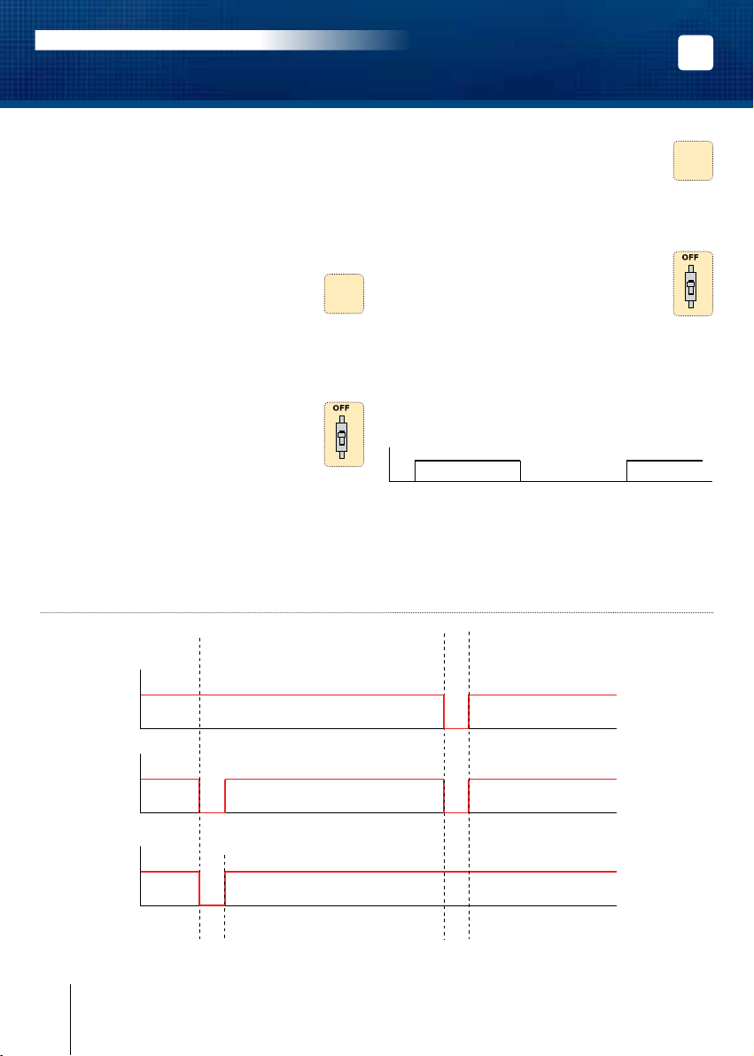
A] ENTRADA EN MODO DE PROGRAMACIÓN
1. Corte la alimentación.
Ponga el switch en ON.
Restablezca la alimentación.
2. Se emitirán dos pitidos para conrmar la
entrada en modo de programación.
El control externo del buzzer no funciona en
modo de programación.
B] PROGRAMACIÓN DE LA ILUMINACIÓN
1. Entre en modo de programación*.
2. Teclee A0 para programar el tiempo de
iluminación del teclado:
- Se emitirá un pitido.
- Teclee la duración en segundos de la
iluminación o teclee «00» para una
iluminación permanente.
- Se emitirá un pitido para conrmar la
programación.
3. Ponga el switch en posición OFF:
- Se emitirán dos pitidos para conrmar
la salida del modo de programación.
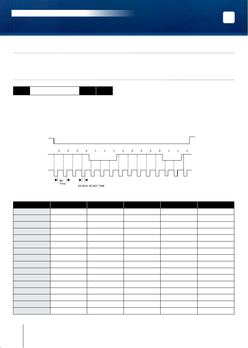
C] PROGRAMMATION DU FORMAT DE SORTIE
1. Entre en modo de programación*.
2. Teclee A1 para programar el formato de
salida:
- Se emitirá un pitido.
- Teclee 1 para formato Wiegand 26 bits.
- Teclee 2 para formato Standard.
- Teclee 3 para formato ISO Track 2.
- Se emitirá un pitido para conrmar validación.
3. Ponga el switch en posición OFF:
- Se emitirán dos pitidos para conrmar
la salida del modo de programación.
D] PROGRAMACIÓN DEL NÚMERO DE DÍGITOS
1. Entre en modo de programación*.
2. Teclee A2 para indicar el número de
dígitos de los códigos de acceso:
- Se emitirá un pitido.
- Teclee 4, 5 o 6 para indicar el nº de dígitos.
- Se emitirá un pitido para conrmar la
validación
3. Ponga el switch en posición OFF:
- Se emitirán dos pitidos para conrmar
la salida del modo de programación.
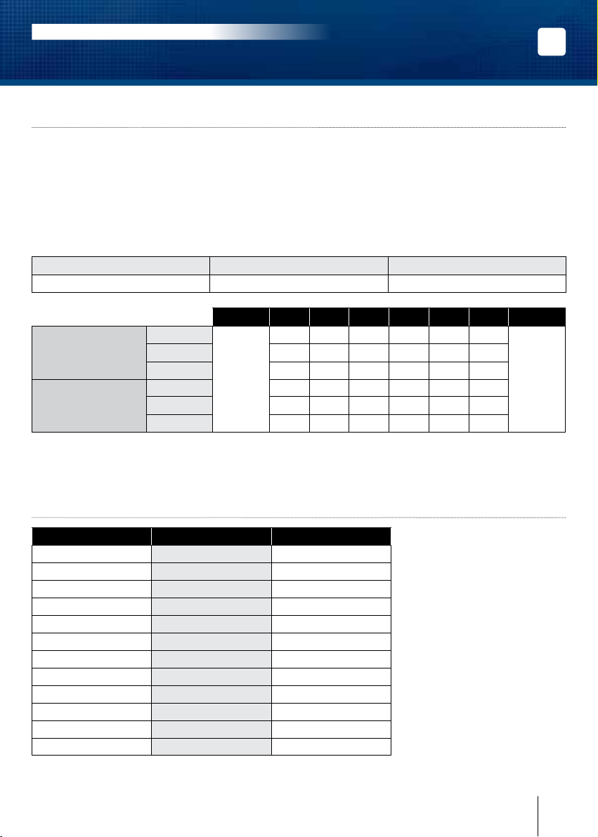
Valores por defecto
- Tiempo de iluminación: 10 segundos.
- Número de dígitos: 5.
- Salida Wiegand 26 bits.
- Buzzer inactivo.
- Modo decimal.
Correspondencia de señales sonoras
- 1 pitido corto > Teclado conectado o tecla
pulsada.
- 1 pitido largo > Dato validado en modo de
programación.
- 2 pitidos cortos > Entrada/Salida de modo de
programación.
- 4 pitidos cortos > Error en datos introducidos.
Acerca de los códigos
- En modo decimal, los códigos de usuario deben
ser de 4, 5 o 6 dígitos. La tecla B se usa para
validar el código introducido.
- En modo hexadecimal, la tecla A no está
permitida.
- En modo ARK, se transmite código con todas
las teclas.
* Consulte el apartado “ENTRADA EN MODO DE PROGRAMACIÓN”.
ES
GALEOW
Teclado Digicode®Wiegand retroiluminado
MANUAL DE INSTALACIÓN