Meccanica Fadini DGT 61 User manual

Via Mantova, 177/A - 37053 Cerea (VR) Italy
Ph +39 0442 330422 Fax +39 0442 331054
[email protected] www.fadini.net
I
DGT 61
GB
F
D
Pulsantiera a codice digitale
Digital Keypad
Clavier codè digital
Digitale Drucktastentafel
E
NL
Tablero de pulsadores con código digital
Drukknoppaneel met digitale code
DGT 61
12-24V
ac/dc
NC
COD. 610L COD. 611L
COD. 612L

DIGITAL KEYPAD
DGT 61
GB
8
GENERAL WARNINGS FOR PEOPLE SAFETY
INTRODUCTION
This operator is designed for a specic scope of applications as
indicated in this manual, including safety, control and signaling
accessories as minimum required with FADINI equipment. □
Any applications not explicitly included in this manual may
cause operation problems or damages to properties and
people. □Meccanica Fadini snc is not liable for damages
caused by the incorrect use of the equipment, or for
applications not included in this manual or for malfunctioning
resulting from the use of materials or accessories not
recommended by the manufacturer. □The manufacturer
reserves the right to make changes to its products without
prior notice. □All that is not explicitly indicated in this manual
is to be considered not allowed.
BEFORE INSTALLATION
Before commencing operator installation assess the suitability
of the access, its general condition and the structure. □Make
sure that there is no risk of impact, crushing, shearing,
conveying, cutting, entangling and lifting situations, which
may prejudice people safety. □Do not install near any source of
heat and avoid contacts with ammable substances. □Keep all
the accessories able to turn on the operator (transmitters,
proximity readers, key-switches, etc) out of the reach of the
children. □Transit through the access only with stationary
operator. □Do not allow children and/or people to stand in the
proximity of a working operator. □To ensure safety in the
whole movement area of a gate it is advisable to install
photocells, sensitive edges, magnetic loops and detectors. □
Use yellow-black strips or proper signals to identify dangerous
spots. □Before cleaning and maintenance operations,
disconnect the appliance from the mains by switching o the
master switch. □If removing the actuator, do not cut the
electric wires, but disconnect them from the terminal box by
loosening the screws inside the junction box.
INSTALLATION
All installation operations must be performed by a qualied
technician, in observance of the Machinery Directive
2006/42/CE and safety regulations EN 12453 - EN 12445. □
Verify the presence of a thermal-magnetic circuit breaker
0,03 A - 230 V - 50 Hz upstream the installation. □Use
appropriate objects to test the correct functionality of the
safety accessories, such as photocells, sensitive edges, etc. □
Carry out a risk analysis by means of appropriate instruments
measuring the crushing and impact force of the main opening
and closing edge in compliance with EN 12445. □Identify the
appropriate solution necessary to eliminate and reduce such
risks. □In case where the gate to automate is equipped with a
pedestrian entrance, it is appropriate to prepare the system in
such a way to prohibit the operation of the engine when the
pedestrian entrance is used. □Apply safety nameplates with CE
marking on the gate warning about the presence of an
automated installation. □The installer must inform and instruct
the end user about the proper use of the system by releasing
him a technical dossier, including: layout and components of
the installation, risk analysis, verication of safety accessories,
verication of impact forces and reporting of residual risks.
INFORMATION FOR END-USERS
The end-user is required to read carefully and to receive
information concerning only the operation of the installation
so that he becomes himself responsible for the correct use of it.
□The end-user shall establish a written maintenance contract
with the installer/maintenance technician (on -call). □Any
maintenance operation must be done by qualied technicians.
□Keep these instructions carefully.
WARNINGS FOR THE CORRECT OPERATION OF THE
INSTALLATION
For optimum performance of system over time according to
safety regulations, it is necessary to perform proper
maintenance and monitoring of the entire installation: the
automation, the electronic equipment and the cables
connected to these.
□The entire installation must be carried out by qualied
technical personnel, lling in the Maintenance Manual
indicated in the Safety Regulation Book (to be requested or
downloaded from the site
www.fadini.net/supporto/downloads).
□Operator: maintenance inspection at least every 6 months,
while for the electronic equipment and safety systems an
inspection at least once every month is required. □The
manufacturer, Meccanica Fadini snc, is not responsible for
non-observance of good installation practice and incorrect
maintenance of the installation.
DISPOSAL OF MATERIALS
Dispose properly of the packaging materials such as
cardboard, nylon, polystyrene etc. through specializing
companies (after verication of the regulations in force at the
place of installation in the eld of waste disposal). Disposal of
electrical and electronic materials: to remove and dispose
through specializing companies, as per Directive 2012/19/UE.
Disposal of substances hazardous for the environment is
prohibited.
UE DECLARATION OF CONFORMITY (DoC)
Manufacturer: Meccanica Fadini snc
Address: Via Mantova, 177/A - 37053 Cerea - VR - Italy
declare that the DoC is issued under our sole responsibility and
belongs to the following product:
Digital Keypad DGT 61
is in conformity with the relevant Union harmonisation legislation:
- Electromagnetic Compatibility Directive 2014/30/UE
- Low Voltage Directive 2014/35/UE
Cerea, 19/04/2017 Meccanica Fadini s.n.c.
Responsible Manager
GB
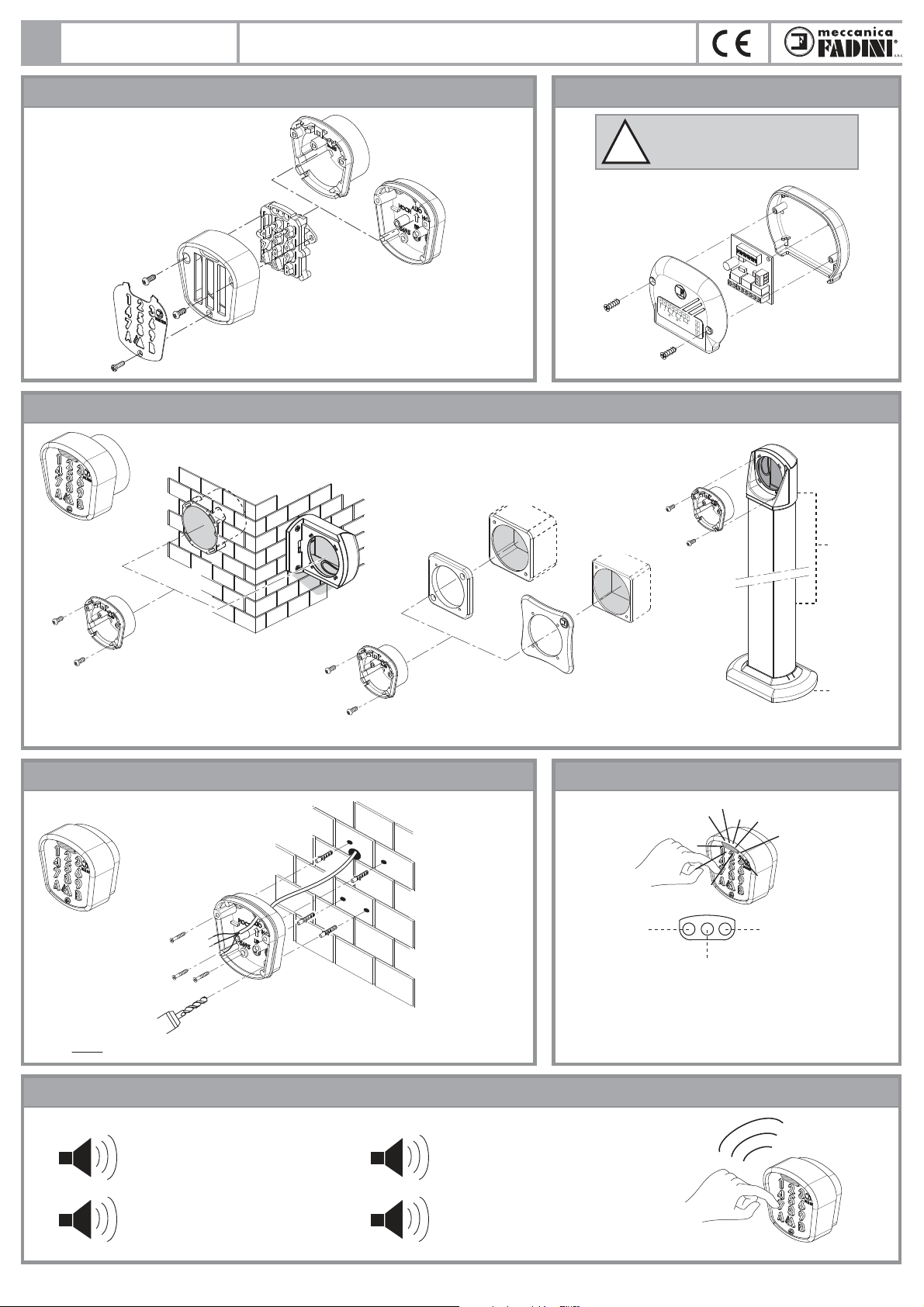
NOTE: screws and expanding bolts not supplied by us.
9
DGT 61
BRINGING THE KEYPAD APART BRINGING THE MAIN PCB APART
Treated aluminium
front unit
GREEN LED:
access code OK
BLUE LED:
• Fixed light: - unit on voltage
- night illumination of the keypad
• Flashing light: professionaly advanced timed
functions in progress
RED LED: wrong
access code
or STOP button
activated
Stainless steel
front cover
Treated aluminium
back casing
surface mount
Plastic back casing
recess mount
Keypad
DGT 61
12-24V
ac/dc
NC
code 612L
LED LIGHTSSURFACE APPLICATION OF THE KEYPAD TO A WALL
SOUND DEVICE
ACCESSORIES TO FIT THE KEYPAD, RECESS APPLICATION
code 552L
code 560L
code 553L
Sech 15 code 557L
code 554L
Prit 19
code 611L
code 558L
code 610L
1
Long Beep: a long beep conrms the
correct access code sequence
n°1 short beep: is emitted whenever
a key button is pressed
n°3 short beeps: the access code
sequence is wrong
n°5 short beeps: memory clearing
carried out correctly
3
5
Pic. 2
Pic. 3
Pic. 1
Pic. 5
Pic. 6
Pic. 4
ATTENTION: This unit is
recommended to be installed in a
safe and sheltered place.
!
DIGITAL KEYPAD

GB
DGT 61 is a custom-encoded control accessory designed to open and close any automatic access system. It can be also used to control other external applications.
DGT 61 consists of a Keypad (in an anti-corrosion treated aluminium casing, in two options either to be partially recessed or surface mounted) cable
connected (x 4 wires) to the Main PCB; this one is to be installed near the Elpro electronic control box for the electrical connections. The keypad incorporates
the button keys, illuminated in blue from the back: nine digits, two outputs A and B and one output for the emergency stop button. The main PCB is tted with a
terminal block where power supply is to be connected (in parallel also to the keypads), with the N.O. contacts of the A and B output relays and with one pure
N.C. terminal output of a third relay, providing connections for an emergency stop. A second block of terminals X and Y (and a third one Z for long distance or
disturbed signals) receive the encoded signal from the keypads. Programming is simple and immediate by Dip-switches on the main PCB. Each channel can
take up to 4 dierent numerical codes; any one code, through the same channel either A or B, operates the same function. Other professionally advanced
functions can be achieved by the two relays (bistable outputs, timed bistable outputs, output delay, etc.), and can be enabled by the Dip-switches on the main
PCB. Other external control applications are also made possible (eg. illumination, alarm systems and watering) besides automatic door/gate systems, etc.
In these cases, it is recommended that a relay be always tted between the PCB and the other possible applications.
10
GENERAL DESCRIPTION
DIAGRAM OF A POSSIBLE INSTALLATION WITH TWO KEYPADS AND ONE PCB
Pic. 7
Pic. 8
Red led 1:
It ashes during
programming phase
Main PCB
1 or more
keypads DGT 61
(*) the connection to the
Z terminal is required in
case of weak or
disturbed signal
12-24V
ac/dc
12-24V
ac/dc
24V
ac/dc
12-24V
ac/dc
12-24V ac/dc STOP
max 0,5mm² up to 100m
Red led 2:
It ashes slowly when X Y are
properly connected to the keypad
Jumper for 12Vdc power supply:
when jumper is tted, 12Vdc
power supply is possible
X Y Z
ABS
CNO NOC NC
C
ON
OFF 1 2 3 4 5 6 7 8 9 10 (*)
1**
ON
ON
3**
ON
4**
ON
2**
ON
ON
ON
ON
1**
2**
3**
4**
relay NO relay NO relay NC
= Pure contact for STOP function only: direct to
the relay in case of an emergency
**once encoding/programming phases are completed, all Dip-switches are to be set to OFF
Automated
access B or
other applications
Automated
access A or
other applications
1st CODE
to relay A
2nd CODE
to relay A
3rd CODE
to relay A
4th CODE
to relay A
Keypad DGT 61 Controll box series
Elpro - access A
Controll box
Elpro 6 - access B
Keypad DGT 61
1st CODE
to relay B
2nd CODE
to relay B
3rd CODE
to relay B
4th CODE
to relay B
X Y Z
1 2 3 4 5 6 7 8 9 10
A B
C NO NOC NCC
X Y Z
3 4 6
X Y Z
3 4
3
33
X Y Z
S
ON
OFF
(*) (*)
(*)
DGT 61
12-24V
ac/dc
NC
open
open
stop
common
open
stop
24Vac/dc
common
open/stop/close
main PCB
relay NO relay NO relay NC
(*) The connection
to Z terminal is
required in case of
weak or disturbed
signal
max 0,5mm²
up to 100m
0,5mm² up to 100m
DGT 61 DIGITAL KEYPAD

GB
STORING ONE OR MORE ACCESS CODES ONTO THE RELAY OUTPUT A
11
!PLEASE NOTE: this operation erases completely all the access codes and any additional functions stored with the relay involved in this process.
DGT 61
1) Carry out the electrical connections to the MAIN PCB (Pic.8).
2) Set only one of the switches DIP 1 or DIP 2 or DIP 3 or DIP 4 to ON (It is
through the rst four DIp-switches that dierent ACCESS CODES can be
stored). The red led 1 on the main PCB ashes.
3) Press the ACCESS CODE (from 1 to 6 digits) - press A.
The green led goes on followed by a long conrming beep.
4) Set all DIP-switches to OFF. The red led 1 on the PCB goes o.
NOTE: The relay A can take up to 4 dierent access codes max. Each code is
to be stored individually by setting any one of the rst 4 DIP-switches to ON.
OFF
1) 3) 4)
1
1
ON 2)
Diagram
relay A
ACCESS
CODE
main PCB
ALL DIP-SW.
TO OFF
main PCB
STORING ONE OR MORE ACCESS CODES ONTO THE RELAY OUTPUT B
1) Carry out the electrical connections to the MAIN PCB (Pic.8).
2) Set only one of the switches DIP 1 or DIP 2 or DIP 3 or DIP 4 to ON (It is
through the rst four DIp-switches that dierent ACCESS CODES can be
stored). The red led 1 on the main PCB ashes.
3) Press the ACCESS CODE (from 1 to 6 digits) - press B.
The green led goes on followed by a long conrming beep.
4) Set all DIP-switches to OFF. The red led 1 on the PCB goes o.
NOTE: The relay B can take up to 4 dierent access codes max. Each code is
to be stored individually by setting any one of the rst 4 DIP-switches to ON.
HOW TO OPERATE WITH DGT 61 KEYPAD
Once satised that the main PCB is properly connected to the Elpro control
box, and the selected ACCESS CODES stored with the required output, to operate
with the keypad just press the keys corresponding to the ACCESS CODE,
followed by the key corresponding to the required OUTPUT (Aor B).
The green led goes on followed a long conrming beeping.
If the access code sequence is
incorrect: the unit gives out 3
beeping souds and the red led
illuminates for 2 seconds. Dial
correctly or reprogram the unit. n°3 short beeps
3
Red led
for 2 seconds
Diagram
OFF
1) 3) 4)
1
1
ON 2)
relay B
ACCESS
CODE
main PCB
ALL DIP-SW.
TO OFF
main PCB
1)
or
ACCESS
CODE
A or B output
Diagram
2)
LONG
BEEPING
green led
for 1 second
ENABLING THE STOP BUTTON KEY
Carry out the electrical connections to the keypad, main PCB and the Elpro
control box (or to a control relay). Pic. 8.
The DGT 61 keypad incorporates also a pure NC contact to get the STOP function.
The contacts of the C - NC terminals on the main PCB are opened on
pulsing the STOP button in the keypad, and no code is required to be entered.
red led
for 2 seconds
main PCB
STOP
pure contact
press
STOP
Diagram
NCC
S
MEMORY CLEARING
1) Set the Dip-sw. 10 to ON. The red led 1
ashes.
2) Press the key 9 9 9 (three times).
3) Press button A or Bto erase the encoding
and the functions from output A or B
4) Set all the DIP-switches to OFF.
5 short beeps conrm the operation
while the green led keeps ashing as
long as beeping can be heard.
5
OFF
4)
10
main PCB
ALL DIP-SW.
TO OFF
or
n°5 Beeps green led
Diagram
main PCB keypad A or B output
1) 2) 3)
ON
10
DIGITAL KEYPAD

GB
12
OFF
1) 3) 4)
5
5
ON 2)
Diagram
A or B output
time in minutes
(max 1439 = 24h)
main PCB
ALL DIP-SW.
TO OFF
main PCB
or
ADDITIONAL FUNCTIONS: can be achieved by the A and B outputs through one or more access codes
OUTPUT DELAY
Connect the main PCB to the control box (Pic. 8) or to the external control relay, then store an access code with required outputs.
Dierent functions can be achieved by one or both of the outputs, but dierent access codes to one relay carry out the same function.
NOTE WELL: functions are reset in case of a power failure, even if instantaneous.
Programming:
1) Set DIP-sw. 5 to ON. The red led 1 on the PCB ashes.
2) Press the number of minutes corresponding to the activation delay as
required (max.1439 minutes).
3) Press output Aor Bthrough which the required function is activated.
4) Set all the DIP-switches to OFF.
Conrmation of the operation: long beep and green led alight for 2 s
Using the function:
Press the access code followed by Aor Bas programmed. The green led goes on
for 1 s followed by an activation beep. The blue led starts ashing and indicates
that the function has been activated.
In order to RESET (the function is cancelled) press the following sequence:
Aor B- access code - A or B
The green led goes on for 1 s followed by a conrmation beep, while the
blue led stays illuminated.
Time
pulse
output
pulse
output
pulse
output
pulse
output
The pulse is delayed (for a number
of minutes) after pressing the access
code.
OFF
1) 3) 4)
6
6
ON 2)
Diagram
A or B output
time in minutes
(max 1439 = 24h)
main PCB
ALL DIP-SW.
TO OFF
main PCB
or
TIMED WITH 2 PULSES
Programming:
1) Set DIP-sw. 6 to ON. The red led 1 on the PCB ashes.
2) Press the number of minutes for the time required after the rst pulse
(max. 1439 minutes).
3) Press either Aor Boutput by which the function is to be activated.
4) Set all the DIP-switches to OFF.
Conrmation of the operation: long beep and green led alight for 2 s
Using the function:
Press the access code followed by Aor Bas programmed. The green led goes on
for 1 s followed by an activation beep. The blue led starts ashing and indicates
that the function has been activated.
In order to RESET (the function is cancelled) press the following sequence:
Aor B- access code - A or B
The green led goes on for 1 s followed by a conrmation beep, while the
blue led stays illuminated.
A pulse is given after the access code
has been pressed and another one is
given after a set time (minutes).
Time
TIMED DELAY
Programming:
1) Set DIP-sw. 8 to ON. The red led 1 ashes.
2) Press the number of minutes for the delay with time 1 (max 1439 minutes).
3) Press either Aor Boutput by which the required function is to be activated.
4) Press the numer of minutes for time 2 (max. 1439 minutes).
5) Press ether Aor Bas set in step 3).
6) Set all the DIP-switches to OFF.
Conrmation of the operation: long beep and green led alight for 2 s
Using the function:
Press the access code followed by Aor Bas programmed.
The green led goes on for 1 s followed by an activation beep.
The blue led starts ashing and indicates that the function has been activated.
In order to RESET (the function is cancelled) press the following sequence:
Aor B- access code - A or B
The green led goes on for 1 s followed by a conrmation beep, while the
blue led stays illuminated.
Each pulse by the access code
delays (for a number of minutes)
the energizing of the timed relay.
OFF
1) 3) 4)
7
7
ON 2)
Diagram
A or B output
press key 7 main PCB
ALL DIP-SW.
TO OFF
main PCB
or
BISTABLE
Programming:
1) Set DIP-sw. 7 to ON. The red led 1 on the PCB ashes.
2) Press only the button key No. 7.
3) Press either Aor Boutput by which the required function is to be actived.
4) Set all the DIP-switches to OFF
Conrmation of the operation: long beep and green led alight for 2 s
Using the function:
Press the access code followed by Aor Bas programmed.
The green led goes on for 1 s followed by an activation beeping.
Each pulse by the access code energizes or
de-energizes the output relay.
ALL DIP-SW.
TO OFF
Diagram
main PCB keypad
time 1 in
minutes
(max 1439)
time 2 in
minutes
(max 1439)
A or B output keypad
or or
1)
ON
8
2) 3)
OFF
8
4) 5)
6)
Time 1 Time 2
DGT 61 DIGITAL KEYPAD

13
GB
Pic. 9
A or B output
A or B outputA or B output
pulse
output
OFF
1) 3) 4)
9
9
ON 2)
Diagram
time in minutes
(max 1439 = 24h)
main PCB
ALL DIP-SW.
TO OFF
main PCB
or
ADDITIONAL FUNCTIONS: can be achieved by the A and B outputs through one or more access codes
TIMED BISTABLE
Programming:
1) Set DIP-sw. 9 to ON. The red led 1 on the PCB ashes.
2) Press the number of minutes corresponding to the activation time as
required (max. 1439 minutes).
3) Press output A or B as required for the function to be activated.
4) Set all the DIP-switches to OFF.
Conrmation of the operation: long beep and green led alight for 2 s
Using the function:
Press the access code followed by Aor Bas programmed.
The green led goes on for 1 s followed by an activation beep.
The blue led starts ashing and indicates that the function has been activated.
In order to RESET (the function is cancelled) press the following sequence:
Aor B- access code - A or B
The green led goes on for 1 s followed by a conrmation beep, while the
blue led stays illuminated.
Time
The relay is energized and remain
energized for the time as set (in minutes).
REMOVING THE ADDITIONAL FUNCTIONS
1) Set DIP-sw. 5 to ON. The red led 1 on the PCB ashes.
2) Press A (or B) - access code - press A (or B).
3) Set all the DIP-switches to OFF.
Conrmation of the operation: long beep and green led alight for 2 s
Steps to cancel the additional functions from the single relay and set the
DGT 61 unit back to normal functioning.
OVERALL DIMENSIONS
TECHNICAL DATA
DGT 61
LONG BEEP gree led
for 2 seconds
ALL DIP-SW.
TO OFF
Diagram
main PCB main PCBACCESS
CODE
or
1)
ON
5
2)
or
OFF
5
3)
DGT 61
12-24V
ac/dc ABNC
91
73
27
40
29 25
54
Ø56
Recess mount keypad
Keypad Surface mount
keypad
Main
PCB
Power supply 2x0,5 mm² 12-24 Vac/dc
Connections to the keypad 4 x 0,5 mm²
Keypad absorption 15 mA
Stand-by relay absorption 4 mA
Energized relay absorption 27 mA
Working temperature -20 °C + 80 °C
N.O. channels 2
N.C. channels 1
Communication distance max 100 m
Output contacts 1 A - 125 V - 60 VA
Keypad protection standards IP 54
PCB protection standards IP 53
DIGITAL KEYPAD
72 mm
74
DGT 61
2018/04
Via Mantova, 177/A - 37053 Cerea (VR) Italy
Ph +39 0442 330422 Fax +39 0442 331054
info@fadini.net www.fadini.net
IDirettiva 2012/19/UE
Smaltimento dei materiali
elettrici ed elettronici
VIETATO GETTARE NEI RIFIUTI
MATERIALI NOCIVI PER L'AMBIENTE
GB Directive 2012/19/UE
Disposal of electric and
electronic material
DO NOT DISPOSE OF AS NORMAL WASTE.
HARMFUL FOR THE ENVIRONMENT
Other manuals for DGT 61
1
This manual suits for next models
3
Table of contents
Other Meccanica Fadini Keypad manuals


