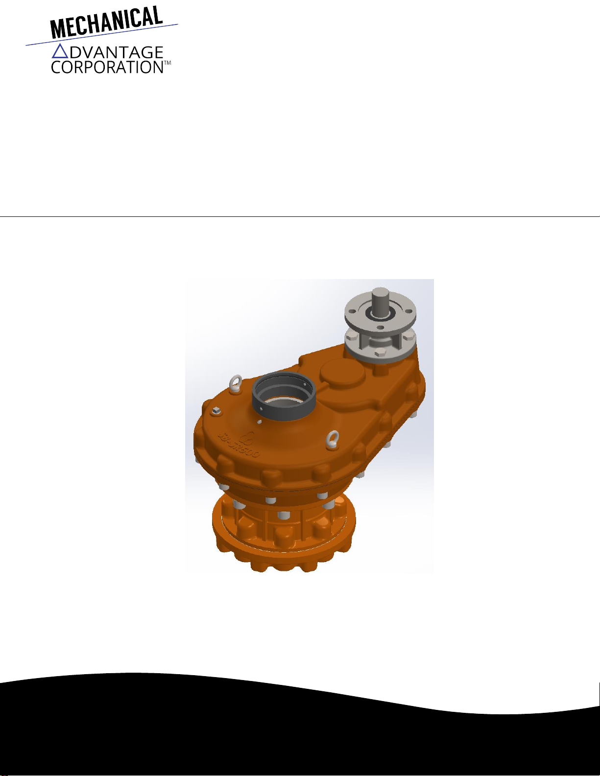
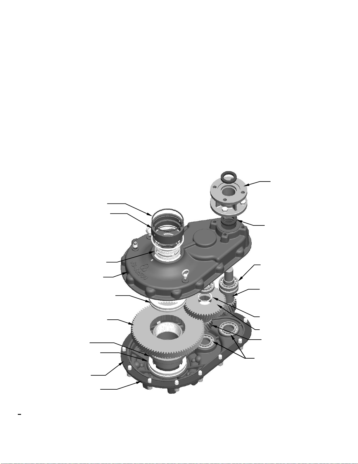
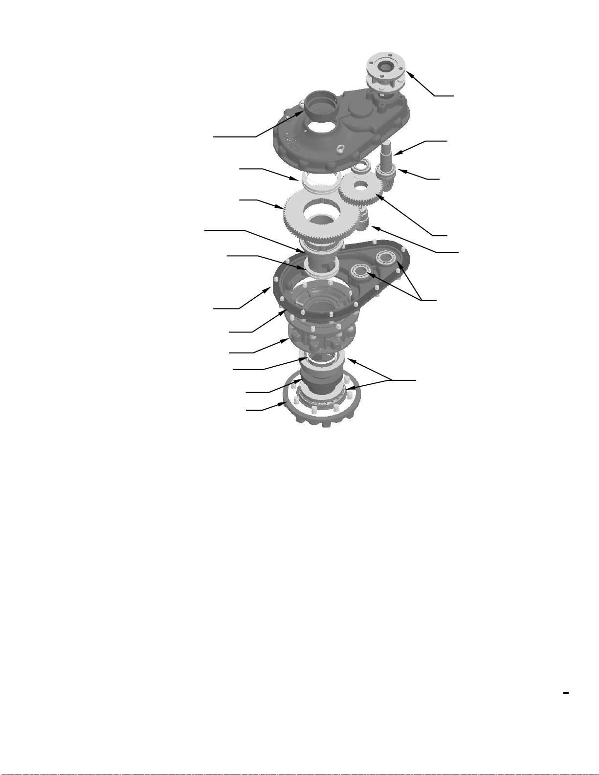
Sambo SB-SR series spur gear
operator
2.3
Storage
Procedure
NOTE:
The following
is
the recommended storage procedure
to
retain maximum product integrity during storage. Failure
to
comply
with
recommended procedure
will
void the
warranty.
Storage (less than one
year)
Store the gearboxes on wooden skids
to
protect the machined mounting flange. Place the wooden skids containing the gearboxes
in
a clean,
dry,
protected warehouse.
If
the gearboxes must be stored outside, they must be covered in polyethylene protection with silica gel crystals
toabsorb
moisture.
If
an electric actuator
is
attached
to
the V gearbox, refer
to
the storage procedures in
its
respective manual
for
appropriate storage
proce-
dures. Rotate input shafts every three months
to
mix the
lubricant.
2.4 Safety
Precautions
c
WARNING:
Read this Installation, Operation and Maintenance manual carefully and completely before attempting
to
install, operate or
trouble-
shoot the SAMBO
gearbox.
c
WARNING:
Potential HIGH-PRESSURE vessel
—
be aware
of
high-pressure hazards associated with the attached valve
or
other actuated
de-
vice when installing or performing maintenance on the gearbox. Do not remove the gearbox mounting bolts from the valve or actuated
device
unless the valve or device stem
is
secured or there
is
no pressure in the
line.
c
WARNING:
For maintenance and/or disassembly
of
the gearbox while installed on the valve, ensure that the gearbox
is
not under thrust
or
torque load.
If
the valve must be left in service, the valve stem must be locked in such a way as
to
prevent any movement
of
the valve
stem.
c
WARNING:
Do not manually operate the gearbox with devices other than the installed handwheel. Using force beyond the ratings
of
the gearbox
and/or using additive force devices such as cheater bars, wheel wrenches, pipe wrenches, or other devices on the gearbox handwheel
may
cause serious personal injury and/or damage
to
the gearbox and
valve.
c
WARNING:
Do not exceed any design limitations
or
make modifications
to
this equipment without first consulting Mechanical Advantage
.
c
WARNING:
Use
of
this product must be suspended any time
it
fails
to
operate
properly.
a
CAUTION:
If
a motor actuator
is
driving the gearbox, do not operatethe valve under motor operation without first checking and setting
the limit switch and checking for correct motor rotation.
a
CAUTION:
Do not use replacement parts that are not genuine SAMBO parts, as serious personal injury and/or damage
tothe
gearbox and
valve may
result.
2.5
Safety
Practices
The following checkpoints should be performed
to
maintain safe operation
of
the SAMBO
gearbox:
•
Set up a periodic operating schedule on infrequently used
valves.
•
Ensure that the limit and/or torque switches on any electric actuator fitted
to
the V gearbox are correctly and appropriately
adjusted.
2.6
General Mounting
Instructions
The mounting instructions
for
the SB bevel gearboxes are outlined
below.
The V0 through V9 gearboxes are designed with a splined top-entry
Stem
Nut which
is
retained in the Drive Sleeve by two Lock
Nuts.
6
The SR200H through SR800H gearboxes are designed with a Stem Nut which
is
retained by two Thrust Roller Bearings within the Thrust Housing
and
Thrust Base. Partial disassembly
of
the Thrust Base
is
required
for
Stem Nut removal and/or
installation.