Mecon mag-flux T4 User manual

mag-ux T4
Magnetic ow meter
compact and separated
OPERATING INSTRUCTIONS
© MECON GmbH BA / mag-flux T4 / EN / 19-04

2© MECON GmbH BA / mag-ux T4 / EN / 19-04
IMPRINT
All rights reserved. Any reproduction or usage without written authorisation of MECON
GmbH - even partial content - is strictly prohibited.
Subject to change without notice.
Copyright 2019 by MECON GmbH - Röntgenstr. 105 - 50169 Kerpen - Germany

3
© MECON GmbH BA / mag-ux T4 / EN / 19-04
Contents
..............................................................................................
1.1 Intended use.......................................................................................................................4
......................................................................................................................5
1.3 Manufacturer’s safety instructions ...............................................................................5
.................................................................................................
2.1 Scope of delivery ...............................................................................................................7
2.2 Nameplate...........................................................................................................................8
.............................................................
3.1 Measuring principle...........................................................................................................9
3.2 System design....................................................................................................................9
3.3 Installation notes...............................................................................................................10
3.4 Installation instructions ...................................................................................................10
3.5 Assembly.............................................................................................................................13
3.6 Electrical connection........................................................................................................16
......................................................................................................................
.........................................................................................................
5.1 Reference conditions........................................................................................................20
5.2 Flow sensor / transducer.................................................................................................20
...............................................................................................................21
5.4 Transducer M1.....................................................................................................................21
5.5 Dimensions coupling connection compact design....................................................22
5.6 Dimensions coupling connection separate design....................................................23
........................................................24
........................................................25
5.9 Dimensions thread connection compact design........................................................26
5.10 Dimensions thread connection separate design........................................................27
........................................................................28
....................................................................................................
.........................................................................................................................
7.1 Storage ................................................................................................................................34
7.2 Maintenance .......................................................................................................................34
7.3 Returning the equipment to the manufacturer..........................................................34
7.4 Disposal ...............................................................................................................................34
........................................................................................................

4© MECON GmbH BA / mag-ux T4 / EN / 19-04
SAFETY INSTRUCTIONS
1
1.1 Intended use
-
-
Warning!
The operator of these measuring devices is solely responsible for the suit-
ability, intended use and corrosion resistance of the selected materials. In
particular. it must be ensured that the materials selected for the wetted
parts of the ow meter are suitable for the process media to be measured.
The meter must not be exposed to external loads. These ow meters are
primarily designed for static applications.
Hot process media can lead to hot surfaces! There is a risk of burns where
the surface temperatures are above +70 °C.
Suitable protective measures should be taken, e.g. protection to prevent
contact.
The contact protection must be designed such that the maximum ambient
temperature around the equipment is not exceeded.
The equipment may only be operated within the pressure and voltage limits stated on the
free of hazardous media and pressure.

5
© MECON GmbH BA / mag-ux T4 / EN / 19-04
SAFETY INSTRUCTIONS
"Return equipment Form" which can be found on the Internet at www.mecon.de/en/
MECON GmbH.
1.2
-
»
»Low Voltage Directive 2014/35/EU
»
»G419006
1.3
-
damages.
relevant product documentation and the valid terms and conditions.
such changes.
The responsibility that the instruments are suitable for the particular application rests solely
-

6© MECON GmbH BA / mag-ux T4 / EN / 19-04
SAFETY INSTRUCTIONS
In case of a complaint the contested elements must be cleaned of hazardous substances
operating instructions carefully before starting to use the equipment.
-
nance of the equipment.
Special designs for special applications and custom models are not covered by this
documentation.
7
© MECON GmbH BA / mag-ux T4 / EN / 19-04
DEVICE DESCRIPTION
2
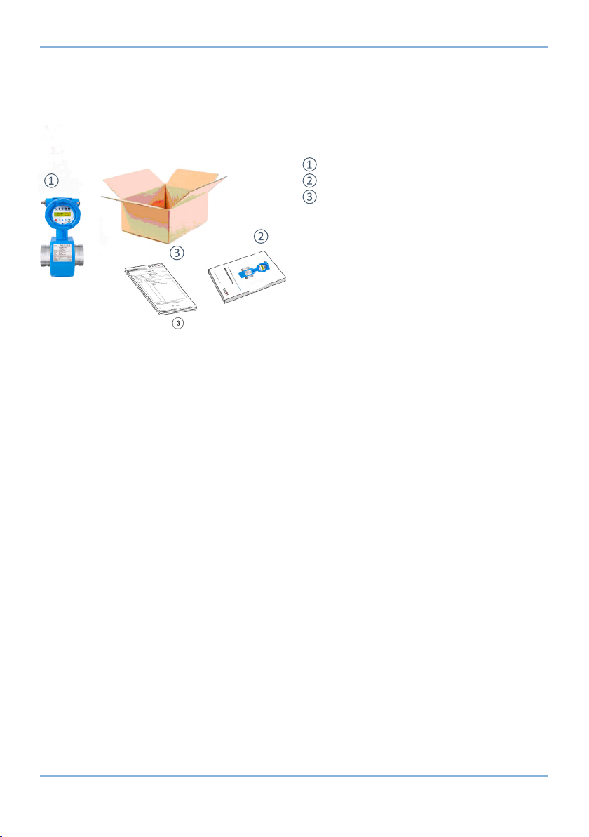
2.1
Operating Instruction
Fig. 1 Scope of delivery
8© MECON GmbH BA / mag-ux T4 / EN / 19-04
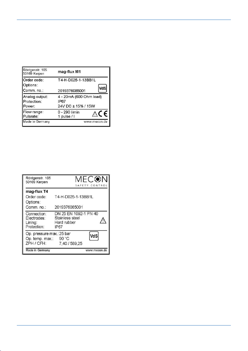
DEVICE DESCRIPTION
Fig. 2 Nameplate mag-ux M1 transducer
2.2
Fig. 3 Nameplate mag-ux T4 sensor
The operating pressure and temperature de-
from the operating instructions.

9
© MECON GmbH BA / mag-ux T4 / EN / 19-04
INSTALLATION AND MODE OF OPERATION
3
-
3.1
of the principle of electrodynamic induc-
-
iments in the Thames were not successful
-
the vector product E = [v x B].
an electrically insulating lining and where
-
at the two electrodes. The magnitude of this measurement voltage is proportional to the
3.2
creates the conditions for the induced voltage applied to the electrodes.
-
Fig. 4 Principle of magnetic inductive ow measure-
ment

10 © MECON GmbH BA / mag-ux T4 / EN / 19-04
INSTALLATION AND MODE OF OPERATION
3.3
Information!
All instruments are carefully checked for proper function before shipment.
On receipt, immediately check the outer packing carefully for damage or
signs of improper handling.
Report damage to the carrier and your local sales sta. In such cases, a
description of the defect, the type and the serial number of the device is
indicated.
Unpack the unit carefully to avoid damage.
Check the delivery against the packing list for completeness. Check the
name plate, if the delivered ow meter according to your order. Check that
the correct voltage supply is specied.
Special requirements VdS: The version with rolled grooved ends may only
be used in combination with VdS-approved pipe couplings manufactured
by Anvil (all Gruvlok mechanical grooved couplings), Jinan Meide (cast-
ing couplings type 1G), Minimax, Modgal, Tyco (Grinnell Mechanical and
G-Fire steel IPS couplings) and Victaulic (except pipe couplings of the type
"Style77").
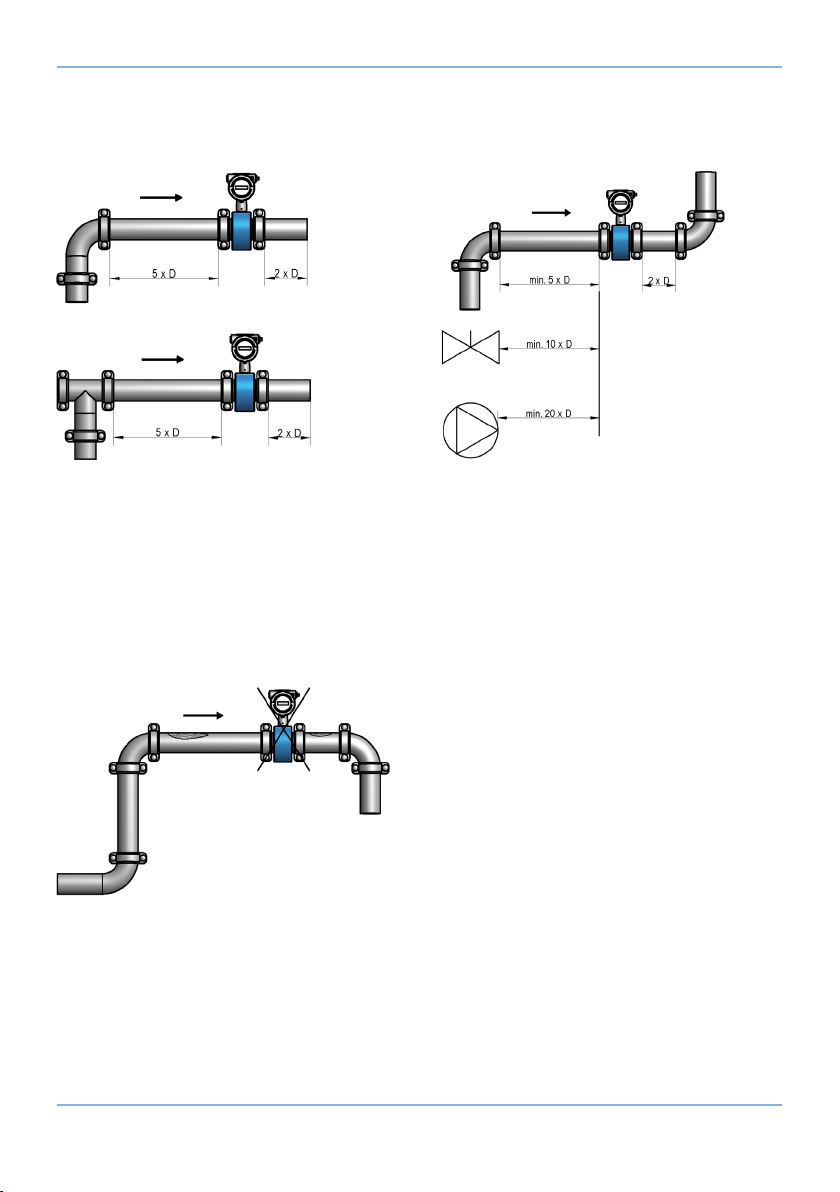
front of and behind the measuring point. An inlet of min. 5 x DN and an outlet of min. 2 x DN
»Enlarging the inlet and outlet sections
»
»Reduction of the pipe cross section
11
© MECON GmbH BA / mag-ux T4 / EN / 19-04
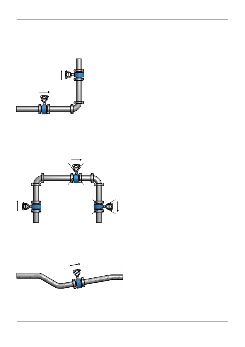
INSTALLATION AND MODE OF OPERATION
Fig. 5 Installation in horizontal and vertical pipelines
Fig. 6 Installation in rising and falling pipes
The sensor must be installed so that the measuring tube can not run empty and is always
Fig. 7 Installation with piping that is always lled
12 © MECON GmbH BA / mag-ux T4 / EN / 19-04
INSTALLATION AND MODE OF OPERATION
straighteners must be used or alternatively the measuring cross-section must be reduced.
Fig. 8 Installation between elbows, valves and pumps (D = DN)
minimum distance is 1 m.
Fig. 9 Installation at the highest point
13
© MECON GmbH BA / mag-ux T4 / EN / 19-04
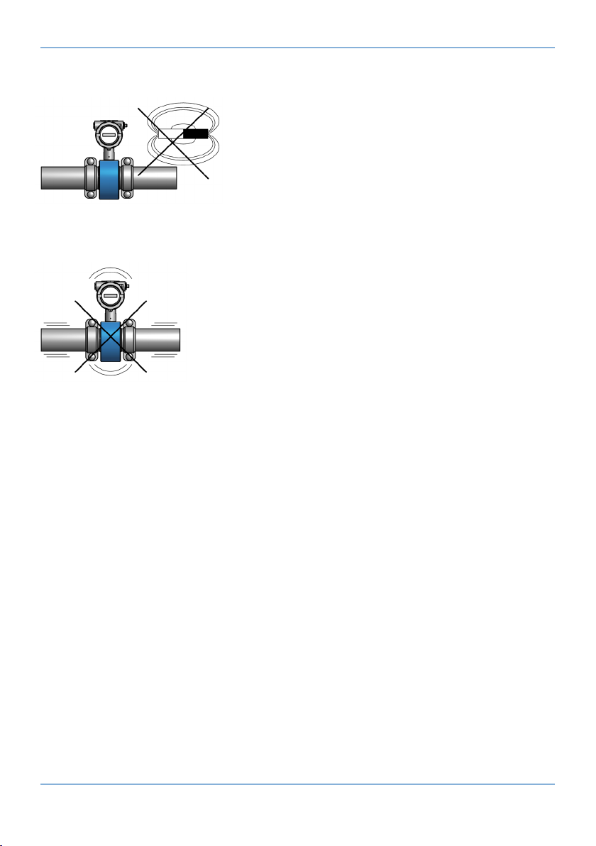
INSTALLATION AND MODE OF OPERATION
Fig. 10 Avoid magnetic elds
Fig. 11 Avoid shocks
3.5
are galvanically insulated from each other and from the measuring circuit. The housing
the measuring electronics are based on the potential of the functional earth FE of the
to the functional earth FE.
When using cathode protection devices which apply a voltage to the pipe wall to prevent

14 © MECON GmbH BA / mag-ux T4 / EN / 19-04
INSTALLATION AND MODE OF OPERATION
The measuring electronics and all operating elements within the transducer now have this
potential too.
electronics technicians or service technicians from MECON GmbH.
Warning!
Before such interventions, the equipment must be completely switched
o, all external devices be disconnected and it must be veried that the
system is no longer live! Only original parts may be used for repair.
accepted for any resulting consequential damages.
Our customer service is at your disposal to provide coordination and assistance with any
necessary diagnostic and repair measures required
This documentation contains the information required for the intended use of the product
-
persons who
»either as an electronics technician or
»a member of maintenance personnel
are familiar with the safety regulations that apply to electrical and automation engineering
and the regulations applicable in your country. They must be authorized by the plant oper-

15
© MECON GmbH BA / mag-ux T4 / EN / 19-04
INSTALLATION AND MODE OF OPERATION
and obey the instructions in them!
The following instructions are for your personal safety and also for avoiding damage to the
described product or any connected devices.
Safety instructions and warnings to prevent danger to the life and health of users or main-
-
Danger!
This means that death, serious injury or signicant damage to property will
occur if the appropriate precautions are not taken!
Warning!
This means that death, serious injury or signicant damage to property
can occur if the appropriate precautions are not taken!
Attention!
This means that slight physical injuries or damage to property may occur if
the appropriate precautions are not taken!
Information!
This is important information about the product, the handling of the
product or the relevant part of the documentation, to which particular
attention should be given.

16 © MECON GmbH BA / mag-ux T4 / EN / 19-04
INSTALLATION AND MODE OF OPERATION
3.6
Tab. 1 Terminal connection diagram
Tab. 2 Pin assignment Power supply 230 V / 115 V
Tab. 3 Connector assignment, Analogue output
1 PN Protective conductor
2 N Mains
3 L Mains (phase)
4Impulse - Pulse output (passive)
5Impulse + Pulse output (passive)
6Status - Status output (passive)
7Status + Status output (passive)
8Power - Power output (active)
9Power + Power output (active)
Pin
(Connection cable)
1brown L / phase
2white PE
3blue N / neutral conductor
4black not used
Pin
(Connection cable)
1brown not used
2white not used
3blue Earth / 0 V
4black not used
5grey Analogue output 4 - 20 mA

17
© MECON GmbH BA / mag-ux T4 / EN / 19-04
INSTALLATION AND MODE OF OPERATION
Tab. 4 Connector assignment Analogue output
Tab. 5 Cable connections with separate design
Fig. 12 Sensor connection of the mag-ux M1 sensor
Pin
(Connection cable)
1brown +24 V
2white not used
3blue Earth / 0 V
4black not used
5grey Analogue output 4 - 20 mA
Pin
(Connection cable)
5brown Magnetic current 1
6white Magnetic current 2
7green yellow Potential equalisation / PE
22 red Measuring earth
23 brown Electrode 1
24 white Electrode 2
* The green-yellow and blue wires are not connected
Fig. 11 Electr. connections of the sensor
mag-ux T4
18 © MECON GmbH BA / mag-ux T4 / EN / 19-04
INSTALLATION AND MODE OF OPERATION
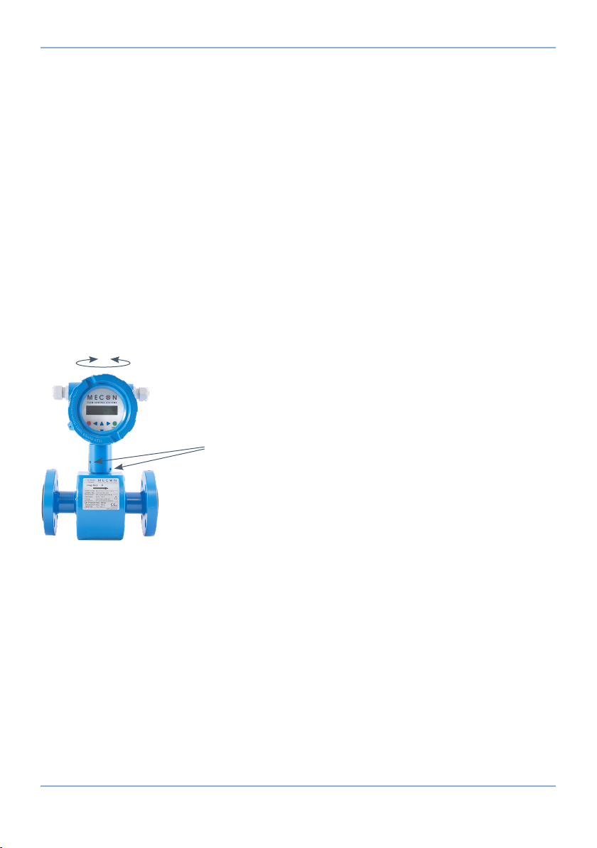
can be extended by max. ± 180°.
display can be read in the correct position with a horizontal installation position and a
1. Loosen the two set screws.
2. The transducer housing must be placed in the desired position.
3. Re-tighten the two set screws.
Fig. 14 Position of the set screws for turning the transducer housing (mag-ux A compact)

19
© MECON GmbH BA / mag-ux T4 / EN / 19-04
The operating instructions are to be read completely before installation and start-up. Only
transducer described in these operating instructions may only be used to measure the
Downloading this document from the homepage www.mecon.de and printing it out for use
with one of our MIDs is permitted. No part of this manual may be reproduced or transmit-
-
ducted by any other means without the prior written consent of MECON GmbH.
-
consequences.
other than as described in this manual.
We reserve the right to change technical data as a result of developmental progress.
The latest information about this product can be found on the Internet at the homepage

20 © MECON GmbH BA / mag-ux T4 / EN / 19-04
TECHNICAL DATA
5
5.1
5.2
30 min.
Inlet section 5 x DN
Outlet section 2 x DN
properly centred
properly earthed
»Process connection /
nominal diameter
Thread connection G½"- G2"
Coupling connection 50/2 "- 300/12"
Flange connection EN 1092-1 DN 15 - DN 300
»Measurement error
»Repeatability
± 0.5% of the measured value from 1 m/s to 10 m/s
± 0.15 % of the measured value from 0.5 m/s to 10 m/s
»Inlet section
»Outlet section
5 x D
2 x D
DN 65 - DN 300
DN 200 - DN 300
DN 15 - DN 150
IP 67
Other manuals for mag-flux T4
1
Table of contents
Other Mecon Measuring Instrument manuals


