manuals.online logo
Brands
  1. Home
  2. •
  3. Brands
  4. •
  5. Vivax Metrotech
  6. •
  7. Measuring Instrument
  8. •
  9. Vivax Metrotech A-frame User manual

Vivax Metrotech A-frame User manual

Disclaimer: Product and accessory specification and availability information is subject to change without prior
notice.
A-frame User Guide V1.1
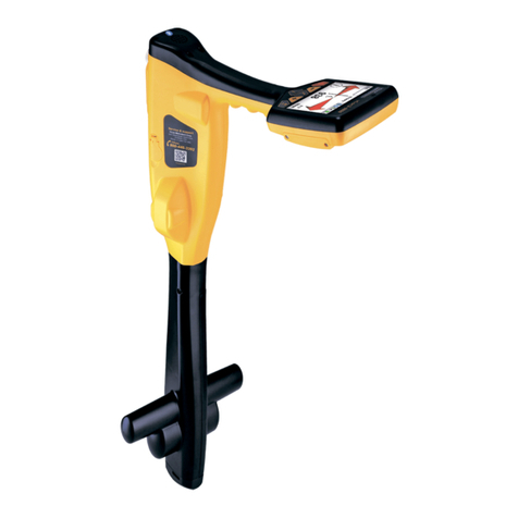
The analogueA-frame accessory is used to detect ground faults on pipes and cables. In the case
of pipes, the faults consist of coating defects. In the case of cables, faults are usually caused by
insulation damage allowing the metallic sheath (or internal conductor) to become in contact with
the ground.
It is intended to be used with the vLoc2 range of locators and will require a fault find signal applied
to the faulty conductor from a Vivax-Metrotech compatible transmitter.
Note
Fault finding requires a non standard signal. Historically there have been many versions of Fault
Find signal. Some of these are listed below:
- 3/6Hz Fault Find (Used to detect faults on pipelines)
- Signal Select Fault Find (Good for fault finding on short runs such as power networks)
Using the Analogue A-frame Fault Finding Accessory
P/N:4.04.000043
Page 1Page 4
Vivax-Metrotech Corp. (Headquarters)
3251 Olcott Street, Santa Clara, CA 95054, USA
T/Free: 800-446-3392
Tel: +1-408-734-1400
Fax: +1-408-734-1415
Email: [email protected]
Website: www.vivax-metrotech.com
Please visit www.vxmt.com for other locations.
WARNING
Always disconnect or isolate target/faulty/suspected cables before
connecting the transmitter to it. Never attach the transmitter to live
cables.
TIP
If it is suspected that there is just one fault, insert the A-frame
approximately one meter from the earth stake. Note the dBuV - this is
approximately the maximum dBuV reading that will be measured over the
fault.
Carefully place the A-frame before and after the fault to pinpoint the position. Repeating this
across the line direction will pinpoint the fault laterally. The fault will be at the point where the
lateral fault is identified.
[email protected] | 13309 Beach Ave. Marina del Rey, CA 90292 | wctproducts.com |
Phone: 800-WCT-PROD (800-928-7763) or 310-822-5212 | Fax: 310-306-9343
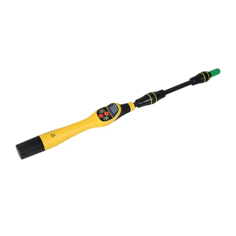
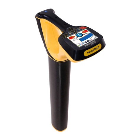
Plug in the analogue A-frame to the receiver accessory socket.When the receiver is switched on,
it will automatically default to the A-frame screen.
Remove the plastic spike covers from the A-frame.Walk along the route of the line placing the
spikes of the A-frame in the ground (with the green leg pointing away from the transmitter
connection point) every two or three paces.If starting near the transmitter, the arrow on the display
will point away from the ground point.As the distance from the transmitter increases, the dBuV
reading will reduce and eventually the arrow will fluctuate or disappear altogether. This is because
the fault location is further along the line. Use the left/right arrows to ensure the A-frame is
positioned over the line and continue placing the A-frame in the ground every two or three paces.
If necessary, use the “M” pushbutton to enter the locate screen allowing the user to confirm the
position of the target line. Press the “M” pushbutton again to re-enter the A-frame mode.
Image for reference only and may differ from actual image
(Note that the A-frame is not shown connected to the receiver so as to simplify the diagram)
Eventually the A-frame will detect the fault signal and the “Fault Find” arrow will point forwards.
Continue moving forwards, it may be worth reducing the distance between measurements points
as the fault is neared.The dBuV reading will increase as the fault is neared. Maximum reading will
be just before and just after the fault. When over the fault, the dBuV reading will drop and the arrow
will flip backwards indicating that the position of the fault has been passed.
Page 2 Page 3
- SD Fault Find (General purpose fault finding)
- 8kHz FF (General purpose fault find with good results on short and long runs and has good
sensitivity)
For the purposes of this manual 8kHz FF is concentrated on as it gives the best overall
performance.
Also note that 8kHz FF is only compatible with the latest analogueA-frame which can be identified
by the 6 pin socket on the A-frame. This was introduced late in 2015. (previously was four pins)
To detect a damaged section, the line should be isolated and have all ground bonding removed.
This will ensure that the ground fault is not masked by deliberate bonding to ground. TheA-frame
cannot distinguish between these two situations.
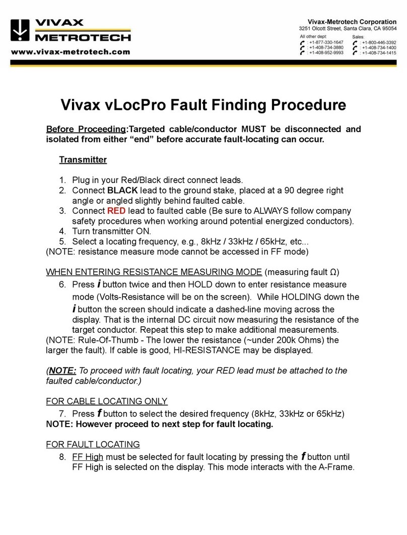
After isolating the line, use the vLocPro2 transmitter resistance measuring function, or a
dedicated resistance measuring device to confirm that there is a fault to ground. TheA-frame will
typically detect faults up to 2 Mohm and above (depending on the distance from transmitter, soil
conditions etc).
Connect the transmitter to the target line using the red lead.A ground stake needs to be pushed
into the ground and the black cable clipped to it. Try to place the ground stake as far as possible
from the line to be evaluated. This ensures return currents do notdistort the results.Switch on the
transmitter and select either 8kFF low or 8kFF high. Use 8kFF high if the line to be surveyed is
long or the fault resistance is high.Make sure the receiver and transmitter are set for the same FF
type, ie 8kFF.
Press + to log
16dBuV
005
8KFF
[email protected] | 13309 Beach Ave. Marina del Rey, CA 90292 | wctproducts.com |
Phone: 800-WCT-PROD (800-928-7763) or 310-822-5212 | Fax: 310-306-9343
Other Vivax Metrotech Measuring Instrument manuals

Vivax Metrotech vLoc3-Cam Instruction Manual

Vivax Metrotech

Vivax Metrotech vLoc3-Cam Instruction Manual

Vivax Metrotech vLocPro2 User manual

Vivax Metrotech

Vivax Metrotech vLocPro2 User manual

Vivax Metrotech vLocPro Series Reference guide

Vivax Metrotech

Vivax Metrotech vLocPro Series Reference guide

Vivax Metrotech vLoc3-9800 Instruction Manual

Vivax Metrotech

Vivax Metrotech vLoc3-9800 Instruction Manual

Vivax Metrotech HL 6000 User manual

Vivax Metrotech

Vivax Metrotech HL 6000 User manual

Vivax Metrotech HL5000 Installation manual

Vivax Metrotech

Vivax Metrotech HL5000 Installation manual

Vivax Metrotech VM-540 User manual

Vivax Metrotech

Vivax Metrotech VM-540 User manual

Vivax Metrotech vLoc3 Series User manual

Vivax Metrotech

Vivax Metrotech vLoc3 Series User manual

Vivax Metrotech vLoc3-MLA Instruction Manual

Vivax Metrotech

Vivax Metrotech vLoc3-MLA Instruction Manual

Popular Measuring Instrument manuals by other brands

Oakton EC250 instruction manual

Oakton

Oakton EC250 instruction manual

PCE Instruments PCE-DC 50 user manual

PCE Instruments

PCE Instruments PCE-DC 50 user manual

PCB Piezotronics 351B31 Installation and operating manual

PCB Piezotronics

PCB Piezotronics 351B31 Installation and operating manual

Greenlee SML-200 instruction manual

Greenlee

Greenlee SML-200 instruction manual

Hach 2100Q Basic user manual

Hach

Hach 2100Q Basic user manual

Spirent NOMAD UX Operation guide

Spirent

Spirent NOMAD UX Operation guide

Tektronix TDP0500 Quick start user manual

Tektronix

Tektronix TDP0500 Quick start user manual

3M Dynatel 965AMS instructions

3M

3M Dynatel 965AMS instructions

Macherey-Nagel URYXXON Relax manual

Macherey-Nagel

Macherey-Nagel URYXXON Relax manual

PR electronics 4511 product manual

PR electronics

PR electronics 4511 product manual

Extech Instruments PS101 user guide

Extech Instruments

Extech Instruments PS101 user guide

YOKOGAWA ADMAG AXR user manual

YOKOGAWA

YOKOGAWA ADMAG AXR user manual

LaMotte Smart 2 Operator's manual

LaMotte

LaMotte Smart 2 Operator's manual

delta-mobrey Hydrastep 2468 Series operating manual

delta-mobrey

delta-mobrey Hydrastep 2468 Series operating manual

PCE Instruments PCE-AM 45 user manual

PCE Instruments

PCE Instruments PCE-AM 45 user manual

Hanna Instruments HI 93709 instruction manual

Hanna Instruments

Hanna Instruments HI 93709 instruction manual

DeWalt DW085LR instructions

DeWalt

DeWalt DW085LR instructions

Micro Motion CDM100P Configuration and Use Manual

Micro Motion

Micro Motion CDM100P Configuration and Use Manual

manuals.online logo
manuals.online logoBrands
  • About & Mission
  • Contact us
  • Privacy Policy
  • Terms and Conditions

Copyright 2025 Manuals.Online. All Rights Reserved.