Warning
7
Overview:
The alarming system of this product has only a set of alarm preset alarm limits. See the factory
default alarming limit (Appendix H) for details.
Alarming limits can be changed and saved with the following alarming limit settings.
Alarming limit value previously saved will be used by default for each start-up of the power-on
alarming system.
If you want to restore the factory default alarming limit, please refer to <<Reset to Factory
Settings>> of <<System Settings>>.
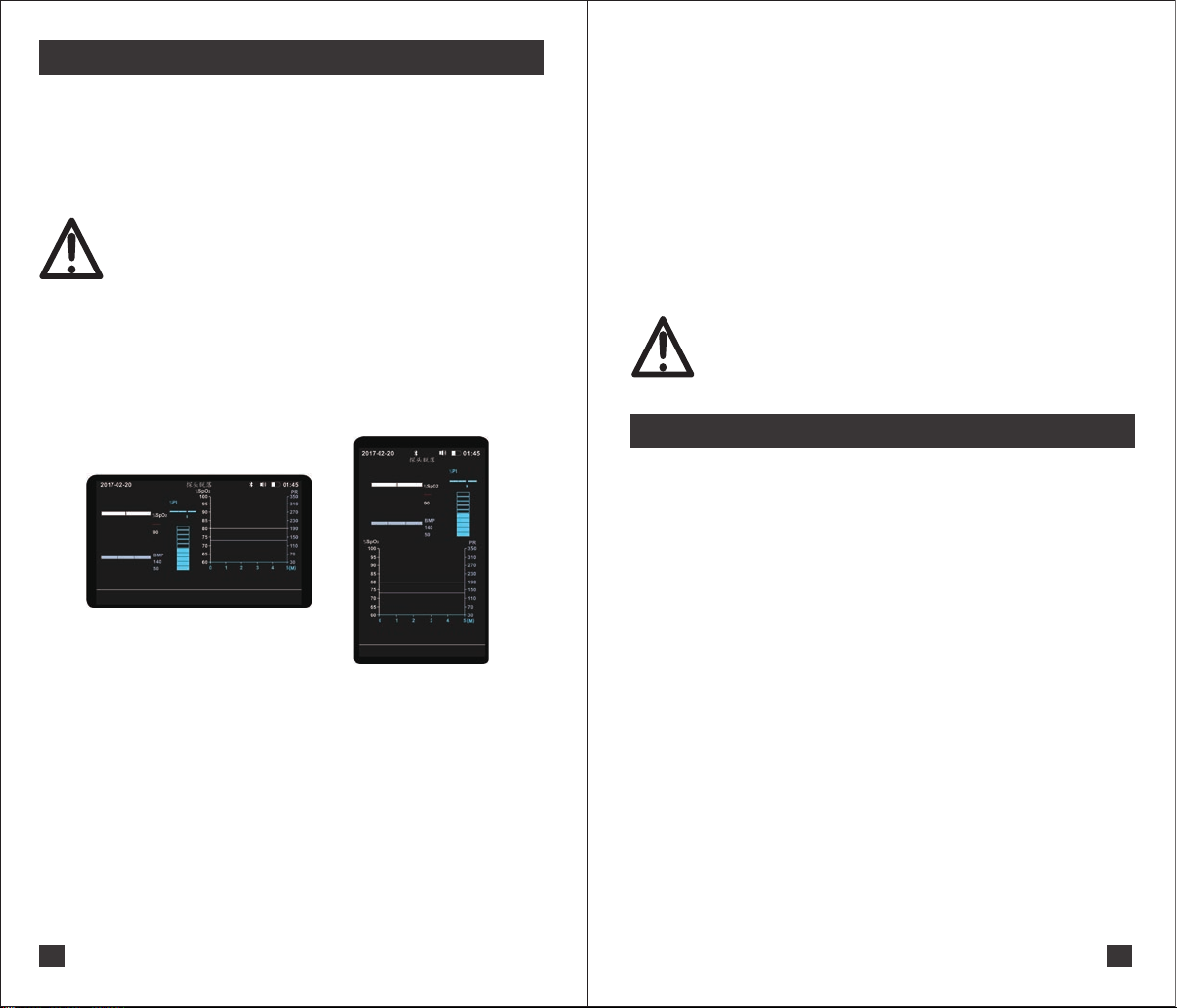
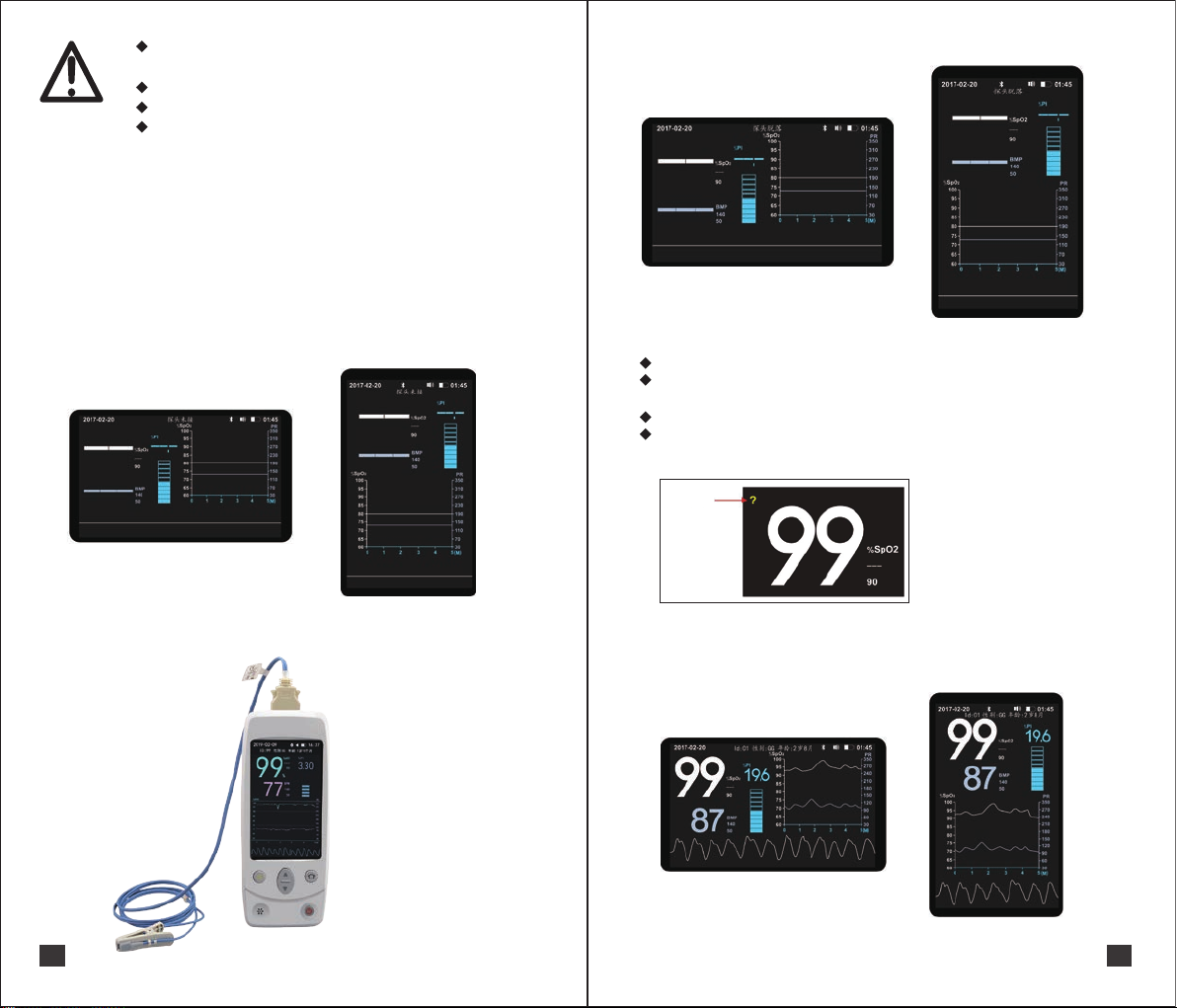
(1)Under the main menu interface, press the set/confirm button for 2 seconds to enter the
alarming Settings menu, as shown in the following figure;
(2)The short press the set/confirm button can switch the alarming value to be set, and the order
is as follows:
SpO2 upper limit alarming value-> SpO2 lower limit alarming value-> PR upper limit alarming
value-> PR lower limit alarming value-> Exit and save alarming value Long Press set/confirm
button can exit and save the alarming value setting, press the up/down button can adjust the
corresponding alarming value.
7 The host uses Spo2 sensor alarming settings
(1) If the lower limit of the alarming line is not valid (i.e., "--"), the upper limit of the alarming line
can be arbitrarily selected from 40% to 99% or invalid (i.e., "--").
(2) If the lower limit of alarming line is 40% ~ 97%, the upper limit of alarming line can be
selected from (lower limit of alarming line +2) ~ 99% or invalid (i.e., "--").
(3) If the lower limit of alarming line is 98% ~ 99%, the upper limit of alarming line can only be
invalid (i.e., "--").
7.1 Adjustment range of SpO2 upper limit alarming value
(1) If the upper limit of the alarming line is not valid (i.e., "--"), the lower limit of the alarming line
can be arbitrarily selected from 40% to 99% or invalid (i.e., "--").
(2) If the upper limit of alarming line is 42% ~ 99%, the lower limit of alarming line can be
selected from 40% ~ (upper limit of alarm line-2) or invalid (i.e., "--").
(3) If the upper limit of the alarming line is between 40% and 41%, the lower limit of the alarming
line can only be invalid (that is, the "--").
7.2 Adjustment range of SpO2 lower limit alarming value
Warning: Please observe whether the current alarming limit is in compliance with
this animal before use.
Note: When the power supply loses at any time, powering up again and starting
the alarming system default to using the previously saved alarming limits.
Figure 6
Warning
8
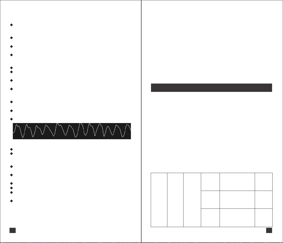
8 Measurement
1) If the lower limit of the alarming line is not valid (i.e., "--"), the upper limit of the alarming line
can be arbitrarily selected from 30 bpm to 350 bpm or invalid (i.e., "--").
2) If the lower limit of the alarming line is 30 bpm ~ 348 bpm, the upper limit of the alarming line
can be selected from (lower limit of alarm line +2) ~ 350 bpm or invalid (i.e., "--").
3) If the lower limit of the alarming line is 349 bpm ~ 350 bpm, the upper limit of the alarming line
can only be invalid (i.e., the "--").
Statement: Please set the system and alarming limit before starting the measurement.
7.3 Adjustment range of upper limit alarming value of PR
1) If the upper limit of the alarming line is not valid (i.e., "--"), the lower limit of the alarming line can
be arbitrarily selected from 30 bpm to 350 bpm or invalid (i.e., "--").
2) If the upper limit of the alarming line is 32 bpm ~ 350 bpm, the lower limit of the alarming line
can be selected from 30 bpm ~ (upper limit of alarm line-2) or invalid (i.e., "--").
3) If the upper limit of the alarming line is 30 bpm to 31 bpm, the lower limit of the alarming line
can only be invalid (i.e., the "--").
7.4 Adjustment range of lower limit alarming value of PR
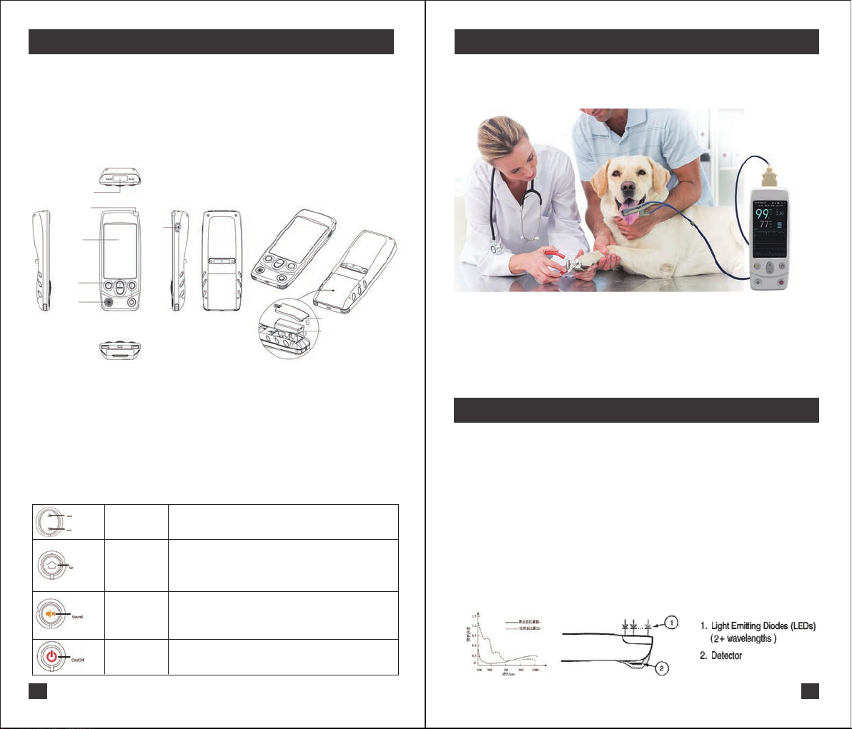
(1)The sensor used in this equipment has a wavelength of red light: 660 nm, infrared light: 905 nm. These
light waves cannot directly illuminate the animal's eyes to avoid injury. When a treatment method similar
to photodynamic therapy is used during the measurement, the wavelength may be interfered to affect the
measurement.
(2)Periodically inspect the main components and accessories of the oximeter to confirm that there are no
obvious damages that may affect the safety and monitoring performance of animal. It is recommended to
check the product before each use. If the oximeter has obvious damage, stop using the product.
(3)when monitoring the tested animals for a long time, the position of the Spo2 sensor attached should be
checked every 2 hours, and the proper movement should be carried out when the skin changes. The
same measuring point should be measured continuously for up to 4 hours. Some tested animals may
need to be examined more frequently, such as those with perfusion disorders or skin sensitivity. Because
prolonged monitoring may increase unpredictable skin changes, such as allergies, redness, blistering or
compression necrosis.
(4)If there is an emergency to turn off the equipment, remove the probe from the sensor to stop the test,
unplug all the accessories in the equipmen and turn off.
(5)Please carefully check the equipment before using this product to confirm that it can be used normally.
(6)The sensor of this oximeter should not be used in the probe or other parts of the arterial catheter, blood
pressure cuff or intravenous injection.
(7)Make sure that the light source comes from the interior of the transparent silica gel. In addition, the light
source will affect the measurement results, including fluorescent lamps, red light source ,infrared water
heaters, direct sunlight and so on.
(8)Frequent activity of the subject or interference from external radio can affect the accuracy of the test.
(9)Only use the sensor specified in this manual and follow the instructions for use. Observe all warnings
and precautions.
(10)High frequency electrosurgical equipment and defibrillators can affect the use of the equipment.
(11)Use the equipment facing the operator and within 1 meter to view the measurement parameters.
8.1 Precautions
Warning:
If different alarming line values are used for the same or similar equipment in any single
area, there may be dangerous. For example, intensive care unit, heart operating room
and so on. Please set different alarming limits according to the condition of each tested
animal, and ensure its safety and effectiveness.