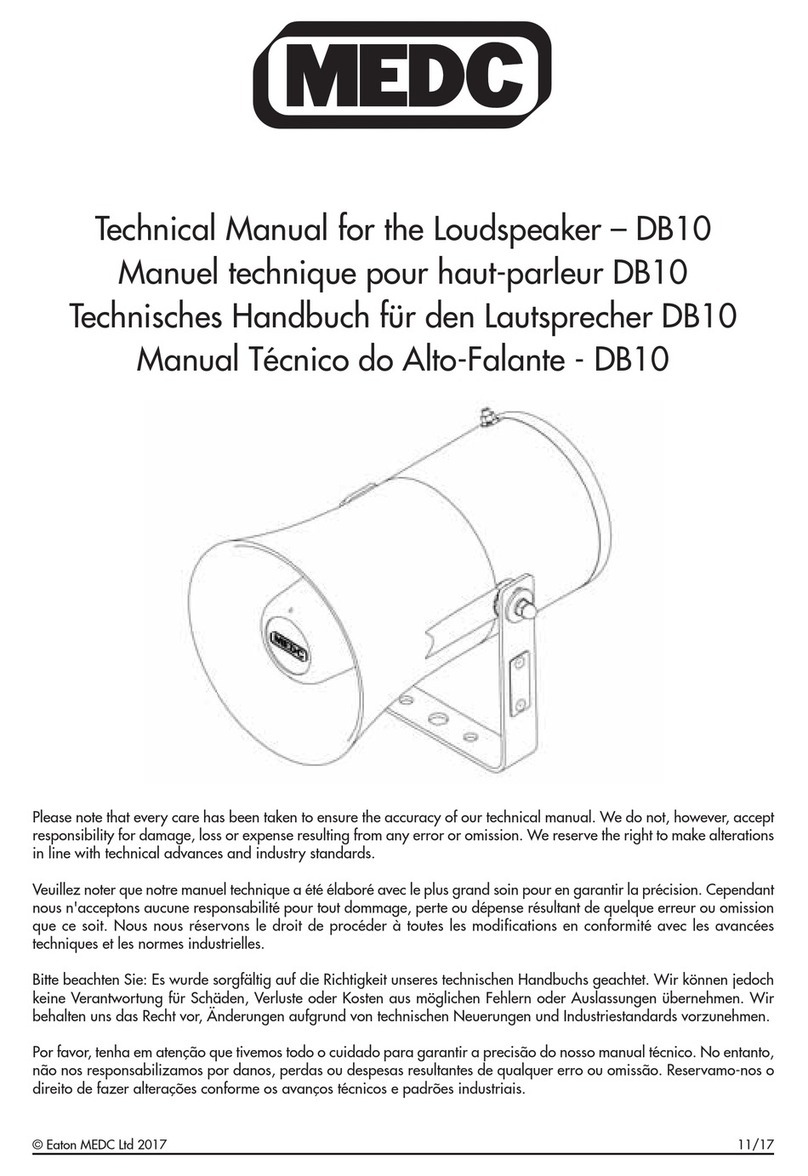
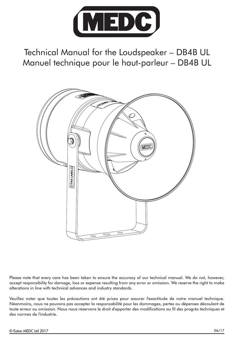
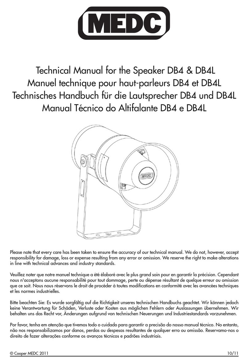
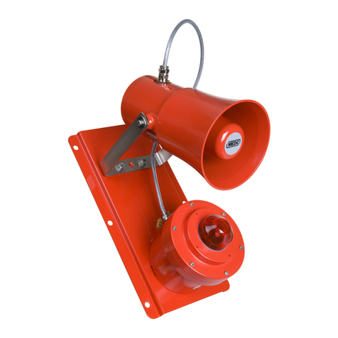
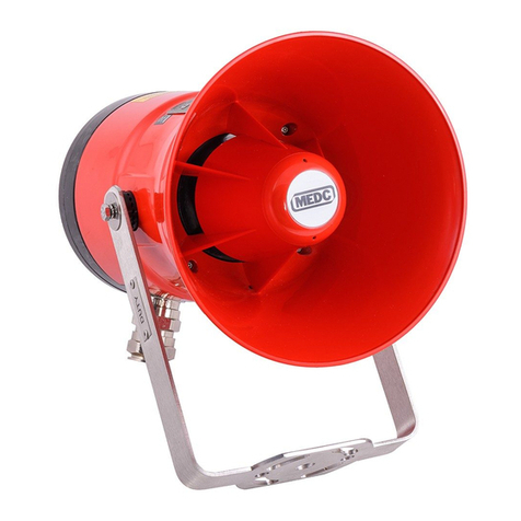
MEDC DB4 User manual

© Cooper MEDC 2011 10/11
Technical Manual for the Speaker DB4 & DB4L
Manuel technique pour haut-parleurs DB4 et DB4L
Technisches Handbuch für die Lautsprecher DB4 und DB4L
Manual Técnico do Altifalante DB4 e DB4L
Please note that every care has been taken to ensure the accuracy of our technical manual. We do not however accept
responsibility for damage loss or expense resulting from any error or omission. We reserve the right to make alterations
in line with technical advances and industry standards.
Veuillez noter que notre manuel technique a été élaboré avec le plus grand soin pour en garantir la précision. Cependant
nous n'acceptons aucune responsabilité pour tout dommage perte ou dépense résultant de quelque erreur ou omission
que ce soit. Nous nous réservons le droit de procéder à toutes modifications en conformité avec les avancées techniques
et les normes industrielles.
Bitte beachten Sie: Es wurde sorgfältig auf die Richtigkeit unseres technischen Handbuchs geachtet. Wir können jedoch
keine Verantwortung für Schäden Verluste oder Kosten aus möglichen Fehlern oder Auslassungen übernehmen. Wir
behalten uns das Recht vor Änderungen aufgrund von technischen Neuerungen und Industriestandards vorzunehmen.
Por favor tenha em atenção que tivemos todo o cuidado para garantir a precisão do nosso manual técnico. No entanto
não nos responsabilizamos por danos perdas ou despesas resultantes de qualquer erro ou omissão. Reservamo-nos o
direito de fazer alterações conforme os avanços técnicos e padrões industriais.


English
1.0 INTRODUCTION
This range of loudspeakers, intended for use in potentially explosive gas and dust atmospheres, has a power rating
of up to 25 watts and is suitable for use in all gas groups including hydrogen.
The flamepaths, flare and the body are manufactured completely from a UV stable glass reinforced polyester.
Stainless steel screws and sinter are incorporated thus ensuring a corrosion free product. A tapered Flamepath is
used to overcome the problems of assembly of parallel spigot flamepaths.
An optional EExe terminal chamber is available
An uncertified version is available for use in non-explosive atmospheres
Models compliant for BS5839 part 8 are also available
2.0 INSTALLATION
General
When installing and operating explosion-protected equipment, requirements for selection, installation and
operation should be referred to eg. IEE Wiring Regulations and the ‘National Electrical Code’ in North America.
Additional national and/or local requirements may apply.
Ensure that all nuts, bolts and fixings are secure.
Ensure that only the correct listed or certified stopping plugs are used to blank off unused gland entry points and
that the NEMA/IP rating of the unit is maintained. MEDC recommend the use of a sealing compound such as
HYLOMAR PL32 on the threads of glands and stopping plugs in order to maintain the IP rating of the unit.
The unit mounts via 2 off !9mm mounting holes in the ‘U’ shaped stirrup / mounting bracket. The holes have been
designed to accept an M8 screw or bolt. If required the unit can be initially placed using the !13mm central hole in
the mounting bracket. The unit can then be rotated into the correct orientation and fixed via the other two holes.
When the unit is fixed in the required position, it’s alignment can be adjusted by loosening the two M6 screws
which fasten the mounting bracket to the speaker. The speaker can then be adjusted to the required position and
the screws tightened. The unit should be positioned such that dust/debris or water cannot settle in the re-entrant
horn.
MEDC recommend the use of stainless steel screws.
Cable Termination
CAUTION: Before removing the cover assembly, ensure that the power to the unit is isolated.
On Exd versions, the cover is secured with 6 off M5 cover screws (4.0mm A/F hexagon key). Once the cover
fixings are unscrewed, twist the cover assembly gently clockwise and anti-clockwise, whilst pulling it away from the
base. Remove to gain access to the interior.
On Exde versions the removable cover is secured using 2 off M5 cover screws (4.0mm A/F hexagon key). Once
the cover fixings are unscrewed, the cover can be lifted away from the enclosure to gain access to the interior.
Ensure all non-captive fixings are kept in a safe accessible location during cable termination.
Cable termination should be in accordance with specifications applying to the required application. MEDC
recommends that all cables and cores should be correctly identified. Please refer to the wiring diagram provided
with the product.
Ensure that only the correct listed or certified cable glands are used and that the assembly is shrouded and correctly
earthed.
All cable glands should be of an equivalent NEMA/IP rating to that of the speaker and integrated with the unit such
that this rating is maintained.
The internal earth terminal, where fitted, must be used for the equipment grounding connection and the external
terminal is for a supplementary bonding connection where local codes or authorities permit or require such a
connection.
Once termination is complete, carefully replace the cover assembly back onto the body, avoiding damage to the
mating surfaces. Replace the cover screws into the holes in the cover assembly and tighten evenly. Ensure the O-
ring is seated correctly on the cover during re-assembly. On Exd certified versions, ensure the required maximum
gap of 0.15mm is maintained between the cover and the base once assembled.
© Cooper MEDC 2011 10/11

3.0 OPERATION
The operating voltage of the unit is stated on the unit label. The speaker is available in 4 standard wattage ratings
from 8 watts to 25 watts and in Exd or Exde versions. Different sound levels can be obtained by selecting the
transformer tappings in the unit. See table below for details.
Alternatively if requested when ordered, the unit can be supplied with a direct 8Ohm connection to the driver for
connecting to a suitable audio source.
Power (W)
Transformer
Tappings 25W 20W 15W 8W
1:2 25.0 20.0 15.0 8.0
2:3 12.5 10.0 7.5 4.0
3:4 6.0 6.0 5.0 2.0
1:3 4.0 5.0 4.0 1.5
2:4 2.0 2.0 2.0 0.7
1:4 1.0 1.5 0.8 0.4
GENERAL ARRANGEMENT
4.0 MAINTENANCE
During the working life of the unit, it should require little or no maintenance. GRP will resist attack by most acids,
alkalis and chemicals and is as resistant to concentrated acids and alkalis as most metal products.
However, if abnormal or unusual environmental conditions occur due to plant damage or accident etc., then visual
inspection is recommended.
If the unit requires cleaning, then only clean exterior with a damp cloth to avoid electro-static charge build up.
Repairs should be undertaken by returning the unit to MEDC or by an authorised repairer of Ex equipment.
If a unit fault should occur, then the unit can be repaired by MEDC. All parts of the unit are replaceable.
If you acquired a significant quantity of units, then it is recommended that spares are also made available. Please
discuss your requirements with the Technical Sales Engineers at MEDC.
10/11 © Cooper MEDC 2011

5.0 CERTIFICATION/APPROVALS
IECEx units
Certified to IEC 60079-0, IEC 60079-1 and IEC 60079-7
Ex d IIC unit (IEC certification No. IECEx BAS 11.0083X)
Ex d IIC T
G
(T
amb.
) Gb
Ex tb IIIC T
D
(T
amb.
) Db IP66
Ex de IIC unit (IEC certification No. IECEx BAS 11.0084X)
Ex de IIC T
G
(T
amb.
) Gb
Ex tb IIIC T
D
(T
amb.
) Db IP66
See special conditions for safe use for ambient temperature ranges and T-ratings
The IECEx certificate and product label carry the IECEx equipment protection level marking
Gb
Db
Where Gb signifies suitability for use in a Zone 1 surface industries area in the presence of gas.
Where Db signifies suitability for use in a Zone 21 surface industries area in the presence of dust.
ATEX units
Certified to EN50014, EN50018 and EN50019
EEx d IIC unit (ATEX certification No. BAS00ATEX2097X)
EEx de IIC unit (ATEX certification No. BAS00ATEX2098X)
See special conditions for safe use for ambient temperature ranges and T-ratings
The ATEX certificate and product label carry the ATEX group and category marking:
II 2 GD
Where:
Signifies compliance with ATEX
II
2
G
D
The ATEX certificate and product label also carry the following mark:
This signifies unit compliance to the relevant European directives, in this case 94/9/EC, along with the number of
the notified body issuing the EC type examination certificate.
Signifies suitability for use in surface industries
Signifies suitability for use in a zone 1 area
Signifies suitability for use in the presence of gases
Signifies suitability for use in the presence of dust
© Cooper MEDC 2011 10/11

6.0 SPECIAL CONDITIONS FOR SAFE USE
a) Type DB4/DB4L - BAS00ATEX2097X (EExd)
1. This apparatus is not suitable for use in atmospheres containing carbon disulphide
2. This apparatus is suitable for use only in ambient temperatures as follows:
Type
Designation
Maximum
Power
Rating
Ambient
Temperature
Range
Temperature
Classification Temperature
Marking
15W -20
o
C to +70
o
CT4 T135
o
C
15W -20
o
Cto +55
o
CT5 T100
o
C
DB4
25W -20
o
C to +55
o
CT4 T135
o
C
15W -55
o
C to +70
o
CT4 T135
o
C
15W -55
o
C to +55
o
CT5 T100
o
C
DB4L
25W -55
o
C to +55
o
CT4 T135
o
C
3. Painting and surface finishes, other than those applied by the manufacturer, are not permitted
4. When used in dust atmospheres the flameproof cable entry devices or stopping plugs shall be selected and
installed to maintain the dust tight (IP6X) integrity of the enclosure
Type DB4/DB4L - IECEx BAS 11.0083X (EExd)
1. This apparatus is not suitable for use in atmospheres containing carbon disulphide
2. This apparatus is suitable for use only in ambient temperatures as follows:
Type Designation Maximum
Power
Rating
Ambient
Temperature
Range
Temperature
Classification Temperature
Marking
15W -20
o
C to +70
o
CT4 T135
o
C
15W -20
o
C to +55
o
CT5 T100
o
C
DB4 25W -20
o
C to +55
o
CT4 T135
o
C
15W -40
o
C to +70
o
CT4 T135
o
C
15W -40
o
C to +55
o
CT5 T100
o
C
DB4L 25W -40
o
C to +55
o
CT4 T135
o
C
3. Painting and surface finishes, other than those applied by the manufacturer, are not permitted
When used in dust atmospheres the flameproof cable entry devices or stopping plugs shall be selected
and installed to maintain the dust tight (IP6X) integrity of the enclosure
b) Type DB4E/DB4LE - BAS00ATEX2098X (EExe)
Type
Designation
Maximum
Power
Rating
Ambient
Temperature
Range
Temperature
Classification Temperature
Marking
15W -20
o
C to +70
o
CT4 T135
o
C
15W -20
o
C to 45
o
CT5 T100
o
C
DB4E
25W -20
o
C to +40
o
CT4 T135
o
C
15W -55
o
C to +70
o
CT4 T135
o
C
15W -55
o
C to +55
o
CT5 T100
o
C
DB4LE
25W -55
o
C to +50
o
C T4 T135
o
C
1. This equipment is not suitable for use in atmospheres containing carbon disulphide.
2. Painting and surface finishes, other than those applied by the manufacturer, are not permitted.
3. When used in a dust atmosphere the cable entries and stopping plugs must maintain the IP66 rating of the
enclosure.
4. Not more than one single or multiple strand lead shall be connected to any terminal unless multiple conductors
have been joined in a suitable manner, e.g. two conductors into a single insulated crimped boot lace ferrule.
5. Leads connected to the terminals shall be insulated for the appropriate voltage and this insulation shall extend to
within 1mm of the terminal throat.
6. All terminal screws, used and unused, shall be tightened down to between 0.5Nm and 0.7Nm.
4.
10/11 © Cooper MEDC 2011

7. The terminals shall only be installed and wired with cable in an ambient temperature of -10
o
C to +80
o
C.
Type DB4E/DB4LE - IECEx BAS11.0084X (EExe)
Type Designation Maximum
Power
Rating
Ambient
Temperature
Range
Temperature
Classification Temperature
Marking
15W -20
o
C to +70
o
C T4 T135
o
C
15W -20
o
C to +55
o
C T5 T100
o
C
DB4E
25W -20
o
C to +50
o
C T4 T135
o
C
15W -40
o
C to +70
o
C T4 T135
o
C
15W -40
o
C to +55
o
C T5 T100
o
C
DB4LE
25W -40
o
C to +50
o
C T4 T135
o
C
1.
2. Painting and surface finishes, other than those applied by the manufacturer, are not permitted.
3. When used in a dust atmosphere the cable entries and stopping plugs must maintain the IP66 rating of the
enclosure.
4. Not more than one single or multiple strand lead shall be connected to any terminal unless multiple conductors
have been joined in a suitable manner, e.g. two conductors into a single insulated crimped boot lace ferrule.
5. Leads connected to the terminals shall be insulated for the appropriate voltage and this insulation shall extend to
within 1mm of the terminal throat.
6. All terminal screws, used and unused, shall be tightened down to between 0.5Nm and 0.7Nm.
7. The terminals shall only be installed and wired with cable in an ambient temperature of -10
o
C to +80
o
C.
This equipment is not suitable for use in atmospheres containing carbon disulphide.
© Cooper MEDC 2011 10/11
7.0 FUNCTIONAL SAFETY
Introduction
The DB4 Speaker has been designed for use in potentially explosive atmospheres and harsh environmental
conditions. The glass reinforced polyester enclosures are suitable for use offshore or onshore, where light weight
combined with corrosion resistance is required.
The DB4 Speaker can be configured with or without an EExe Chamber on the rear.
The FMEDA has considered the worst case scenario which includes the EExe Chamber on the rear.
The safety function of the Sounder is to provide an audible warning when required.
Under No fault (Normal) Operating conditions the DB4 Speaker will provide an audible warning when required.
Under fault conditions the failure mode of the Speaker is a failure to provide an audible warning sound. For the
failure rate associated with this failure mode please refer to the table below.
Assessment of Functional Safety
The DB4 Speaker is intended for use in a safety system conforming to the requirements of IEC61508.
Sira Test & certification Ltd has conducted a Failure Modes Effect and Diagnostic Analysis (FMEDA) of the DB4
Speaker unit against the requirements of IEC61508-2 using a proof test interval of 8760hrs.
The DB4 Speaker is classed as a Type A device.
S
λ

T
Proven in Use Summary Table
DB4 SPEAKER
Safety Function of the DB4 Speaker:
To provide an audible warning sound when required’
Architectural constraints:
Type A
HFT=0
SFF = 85.00%
Proof Test Interval
=8760Hrs
MTTR = 8 Hrs
SIL2
Random hardware failures: λ
DD
= 0
λ
DU
= 4.70E-07
λ
SD
= 0
λ
SU
= 2.86E-06
Probability of failure on demand: PFD
AVG
=2.06E-03
(Low Demand Mode)
SIL2
Probability of Dangerous failure on safety function: PFH = 4.70E-07
(High Demand Mode)
SIL2
Hardware safety integrity compliance Route 1
H
Systematic safety integrity compliance Route 1
S
Systematic Capability SC2
Overall SIL-capability achieved
SIL 2 (Low Demand)
SIL 2 (High Demand)
10/11 © Cooper MEDC 2011
MEDC Stock No.
T TM143-ISS. G
E
W

© Cooper MEDC 2011 10/11
Conditions of Safe Use
The following conditions apply to the installation, operation and maintenance of the assessed equipment. Failure to
observe these may compromise the safety integrity of the assessed equipment:
1. The user shall comply with the requirements given in the manufacturer’s user documentation (This Safety
Manual and Technical manual) in regard to all relevant functional safety aspects such as application of use,
installation, operation, maintenance, proof tests, maximum ratings, environmental conditions, repair, etc;
2. Selection of this equipment for use in safety functions and the installation, configuration, overall validation,
maintenance and repair shall only be carried out by competent personnel, observing all the manufacturer’s
conditions and recommendations in the user documentation.
3. All information associated with any field failures of this product should be collected under a dependability
management process (e.g., IEC 60300-3-2) and reported to the manufacturer.
4. The unit should be tested at regular intervals to identify any malfunctions; in accordance with this safety
manual.
MEDC Stock No.
T TM143-ISS. G
E
W
rv
eUsefaS
f
o
of
snoitidnoC
o
t
to
ylppasnoitidnocgniwoll
o
f
fo
ehT esimorpmocyameeshte
v
r
esbo
1. thtiwylpmocllahserusehT unamlacinhecTdnaluanaM niam,noitarepo,noitallatsni
2. ftnempui
d
sihtfonoitceSel ahsriaper
d
eq
naecnanetniam adenmmocerdnasnoitidnoc
3diifillA
ty
ty
ty
etniamdnanoitaerpo,noitallatsniehto uieqedsesssaehtfo
y
t
iregtni
y
et
faseht
mehtnienvigstnemeriueqreh utcafuna lanoitcnuftnaveelrllaotdraegrni)lua sgnitarmumixam,stestfoorpe,cnaentn
atsniehtdnasnoitcnuf
y
et
f
fet
asnieusr
o
f
fo
eptenetpmocybutodeirracebylnolla oita .noitatnemucoderusehtnisn
dihflifdlifhi
ty
rv
uliaF.tnempiueqedsesssaehtfoecnane :tenmpi
erur ’ y
et
f
fe
aSsihT(noitatenmucodreuss usfonoitacilppasahucsstcepsa
y
et
fas ,riaepr,snoitidnoclatnemnoriven, ;cet
noitadilavllaervo,noitarugifnoc,noitall rerutcafunamehtllagni
v
r
esbo,elnnosr
bddddllbdlh
oteru
e,s
,n
r’s
ilib
3. wd
e
t
te
aicossanoitarmofnillA ,g..e(ssecorptnemgeanam
4. taedtestebdluohstinuehT .luanam
fy
rv
stcudor
p
sihtfosreuliafdleifynahtiw 00306ECI -3- mehtot
d
p
e
t
te
ropredna)2
nuflamyna
y
f
itnediotsla
v
er
tniraulger
badnepedarednudetcellocebdluohs rreutcafunam .
y
et
f
fet
assihthtiwecnadroccani;snoitcn
ty
y
t
ilib

Français
1.0 INTRODUCTION
Cette gamme de haut-parleurs, conçus pour être utilisés dans des atmosphères gazeuses potentiellement explosives,
offre une puissance nominale allant jusqu’à 25Watts et peut être utilisée dans tous les des groupes de gaz, y
compris l'hydrogène.
Les membranes antidéflagrantes, le pavillon et le corps sont entièrement fabriqués en polyester renforcé de fibre de
verre résistant aux UV. Des vis et un frittage en acier inoxydable sont inclus afin de garantir un produit résistant à
la corrosion. Une membrane antidéflagrante conique est utilisée afin de résoudre les problèmes d’assemblage de
membranes antidéflagrantes à ergots parallèles.
Une chambre de borne EExe est disponible en option.
Une version non certifiée est disponible pour une utilisation en atmosphères non-explosives.
Des modèles conformes aux spécifications BS5839 section 8 sont également disponibles.
2.0 INSTALLATION
Généralités
Pour installer et faire fonctionner un équipement protégé contre les explosions, les conditions relatives au choix, à
l'installation et au fonctionnement doivent se reporter, par exemple, à l’IEE Wiring Regulations (réglementation IEE
du câblage) et au National Electrical Code (« code électrique national ») de l'Amérique du Nord. Il est possible que
d'autres conditions nationales et/ou locales doivent s'appliquer.
Vérifier que les écrous, boulons et fixations sont correctement serrés.
S’assurer que seuls des bouchons obturateurs répertoriés ou certifiés sont utilisés pour obturer les points d'entrée
des presse-étoupes inutilisés et que la classification NEMA/IP de l'appareil est conservée. Nous recommandons
l'utilisation de la pâte HYLOMAR PL32 sur le filetage de tous les bouchons et presse-étoupes afin de maintenir la
classification IP de l'appareil.
L’appareil est monté au moyen de deux trous de fixation de Ø9 mm dans la plaque de fixation/l’étrier en « U».
Les trous de fixation ont été conçus pour accepter une vis ou un boulon M8. Au besoin, l’appareil peut d’abord être
positionné à l’aide du trou central de !13mm placé sur la plaque de fixation. Ensuite, vous pouvez faire pivoter
l’appareil dans le bon sens et le fixer à l’aide des deux autres trous.
Une fois l’appareil fixé dans la position requise, son alignement peut être ajusté en dévissant les deux vis M6 qui
relient la plaque de fixation au haut-parleur. Ensuite, le haut-parleur peut être ajusté dans la position requise et les
vis resserrées. L’appareil doit être positionné de sorte que de la poussière/des débris ou de l’eau ne puissent pas
s’infiltrer dans le cornet rentrant.
Nous recommandons l'utilisation de vis en acier inoxydable.
Terminaison des câbles
ATTENTION : Avant de procéder à la dépose du couvercle, vérifier que l'équipement est hors circuit.
Sur les versions Exd, le couvercle est sécurisé à l’aide de 6 vis M5 (clé hexagonale 4,0mm A/F). Une fois les
fixations du couvercle dévissées, faites doucement tourner le couvercle de protection dans le sens des aiguilles
d’une montre et dans le sens antihoraire, tout en le dégageant de la base. Retirez-le pour accéder à l’intérieur.
Sur les versions Exde, le couvercle amovible est sécurisé à l’aide de 2 vis M5 (clé hexagonale 4,0mm A/F). Une
fois les fixations dévissées, le couvercle peut être dégagé du boîtier afin d’accéder à l’intérieur.
Assurez-vous que toutes les fixations non captives sont conservées dans un lieu sûr, accessible pendant le
raccordement des câbles.
Les terminaisons de câbles doivent être conformes aux spécifications correspondant à l’application requise. Nous
recommandons que tous les câbles et fils soient correctement identifiés. Veuillez vous référer au schéma de câblage
fourni avec ce produit.
Assurez-vous que seuls les presse-étoupes énumérés ou certifiés corrects sont utilisés et que l'assemblage est
enveloppé et correctement relié au sol.
Tous les presse-étoupes doivent avoir une classification NEMA/IP équivalente à celle du haut-parleur et être
intégrés à l'appareil de manière telle que la classification soit conservée.
La borne interne de mise à la terre (si installée), doit être utilisée pour la fixation au sol de l'équipement et la borne
extérieure sert de raccordement supplémentaire lorsque les codes ou autorités locales autorisent ou requièrent cette
10/11 © Cooper MEDC 2011

connexion.
Une fois le raccordement terminé, abaissez soigneusement le couvercle de l'assemblage sur la base, en évitant
d'endommager les surfaces de jointement. Remettez les vis dans les trous du couvercle et serrez-les uniformément.
Assurez-vous que le joint torique est correctement en place dans sa gorge pendant le remontage. Sur les versions
Exd certifiées, une fois l’assemblage terminé, assurez-vous que l’espace maximum requis de 0,15mm est maintenu
entre le couvercle et la base.
3.0 FONCTIONNEMENT
La tension d'alimentation de l'appareil est indiquée sur l’étiquette. Le haut-parleur est disponible dans 4 puissances
nominales standards allant de 8 à 25Watts et dans des versions Exd ou Exde. Différents niveaux sonores peuvent
être obtenus en fonction des différents branchements du transformateur au sein de l'appareil. Voir le tableau ci-
dessous pour plus de détails.
D'autre part, si stipulé lors de la commande, l'appareil peut être fourni avec une connexion directe de 8 ohms au
conducteur afin d'être relié à une source audio adaptée.
Puissance (W)
Branchements du
transformateur 25W 20W 15W 8W
1:2 25,0 20,0 15,0 8,0
2:3 12,5 10,0 7,5 4,0
3:4 6,0 6,0 5,0 2,0
1:3 4,0 5,0 4,0 1,5
2:4 2,0 2,0 2,0 0,7
1:4 1,0 1,5 0,8 0,4
DISPOSITION GÉNÉRALE
4.0 ENTRETIEN
Pendant sa durée de vie, l'appareil ne nécessite que peu de maintenance, voire aucune. Le GRP (polyester renforcé
de fibre de verre) résistera à l'attaque de la plupart des acides, alcalis et produits chimiques et il est aussi résistant
aux acides et aux alcalis concentrés comme la plupart des produits en métal.
Cependant, si des conditions environnementales anormales ou peu communes se produisent en raison de dégâts,
accident ou autre ayant eu lieu à l'usine, une inspection visuelle est recommandée.
Si l'appareil a besoin d'être nettoyé, nettoyez seulement l'extérieur avec un tissu humide pour éviter l'accumulation
de charge électrostatique.
Les réparations doivent être effectuées en renvoyant l’appareil à MEDC ou par un réparateur agréé de
l’équipement Ex. Toutes les pièces de l'appareil peuvent être remplacées.
En cas de panne de l'appareil, nous pouvons en effectuer la réparation. Toutes les pièces de l'appareil peuvent être
© Cooper MEDC 2011 10/11
VERSION 8W
CHAMBRE
EExe OPTIONNELLE
SANS LA CHAMBRE EExe
TROUS DE FIXATION
(2 POSITION)
2 x ENTRÉES M20 MAX.
(CHAMBRE EExe)
2 x ENTRÉES M20
(CHAMBRE EExe)
POUR APPAREIL EExd. POSITION 2 DE LA CHAMBRE Eexd
EST UTILISÉE SEULEMENT SI 1 x ENTRÉE M20 REQUISE
CHAMBRE
EExe OPTIONNELLE
SANS LA CHAMBRE EExe
VERSIONS
15W - 25W
TROU DE FIXATION Ø13±1

remplacées.
Si vous achetez une quantité significative d'unités, il est recommandé d'avoir aussi des pièces de rechange
disponibles. Veuillez discuter de vos besoins avec les ingénieurs de vente techniques de MEDC.
5.0 CERTIFICATION/HOMOLOGATIONS
Appareils IECEx
Certifiés conformes aux normes IEC 60079-0, IEC 60079-1 et IEC 60079-7
Appareil Ex d IIC (certification IEC N° IECEx BAS 11.0083X)
Ex d IIC T
G
(T
amb.
) Gb
Ex tb IIIC T
D
(T
amb.
) Db IP66
Appareil Ex de IIC (certification IEC N° IECEx BAS 11.0084X)
Ex de IIC T
G
(T
amb.
) Gb
Ex tb IIIC T
D
(T
amb.
) Db IP66
Veuillez consulter les conditions spéciales pour une utilisation sûre et afin de connaître les gammes de températures
ambiantes et les classes de températures.
Le niveau de protection de l'équipement IECEx est indiqué sur le certificat IECEx et l'étiquette du produit.
Gb
Db
Où Gb signifie approprié pour être utilisé dans un secteur industriel de Zone 1 en présence de gaz.
Où Db signifie approprié pour être utilisé dans un secteur industriel de Zone 21 en présence de poussière.
Appareils ATEX
Certifiés conformes aux normes EN50014, EN50018 et EN50019
Appareil EEx d IIC (certification ATEX N° BAS00ATEX2097X)
Appareil EEx de IIC (certification ATEX N° BAS00ATEX2098X)
Veuillez consulter les conditions spéciales pour une utilisation sûre et afin de connaître les gammes de températures
ambiantes et les classes de températures.
La catégorie et le groupe ATEX sont indiqués sur le certificat ATEX et l'étiquette du produit :
II 2 GD
Où :
Signifie en conformité avec ATEX
II
2
G
D
Le certificat ATEX et l'étiquette du produit portent aussi le label suivant :
Ceci indique la conformité de l'appareil avec les directives européennes appropriées, dans le cas présent, la
directive 94/9/CE, ainsi que le numéro de l'organisme délivrant le certificat d'examen de type « CE ».
Signifie approprié pour être utilisé dans un secteur industriel
Signifie approprié pour être utilisé dans une zone 1
Signifie approprié pour être utilisé en présence de gaz
Signifie approprié pour être utilisé en présence de poussière
10/11 © Cooper MEDC 2011

6.0 CONDITIONS SPÉCIALES POUR UNE UTILISATION SÛRE
a) Type DB4/DB4L - BAS00ATEX2097X (EExd)
1. Cet appareil n’est pas conçu pour être utilisé dans des atmosphères contenant du sulfure de carbone
2. Cet appareil est uniquement conçu pour être utilisé aux températures ambiantes suivantes :
Type Puissance
nominale
max.
Plage de température
ambiante
Classification
de la
température
Marquage de
la
température
15W -20
o
Cà +70
o
CT4 T135
o
C
15W -20
o
Cà +55
o
CT5 T100
o
C
DB4
25W -20
o
Cà +55
o
CT4 T135
o
C
15W -55
o
C à +70
o
CT4 T135
o
C
15W -55
o
C à +55
o
CT5 T100
o
C
DB4L
25W -55
o
C à +55
o
CT4 T135
o
C
3. La peinture et les traitements de surface, autres que ceux appliqués par le fabricant, sont interdits.
4. En cas d’utilisation en atmosphères poussiéreuses, des dispositifs d’entrée de câble antidéflagrants ou des
presse-étoupes doivent être sélectionnés et installés afin de maintenir l’intégrité d'étanchéité du boîtier à la
poussière (IP6X).
Type DB4/DB4L - IECEx BAS 11.0083X (EExd)
1. Cet appareil n’est pas conçu pour être utilisé dans des atmosphères contenant du sulfure de carbone
2. Cet appareil est uniquement conçu pour être utilisé aux températures ambiantes suivantes :
Désignation du type Puissance
nominale
max.
Plage de
température
ambiante
Classification
de la température Marquage de
la température
15W -20
o
C à +70
o
CT4 T135
o
C
15W -20
o
C à +55
o
CT5 T100
o
C
DB4
25W -20
o
C à +55
o
CT4 T135
o
C
15W -40ºC à +70ºC T4 T135
o
C
15W -40ºC à +55ºC T5 T100
o
C
DB4L
25W -40ºC à +55ºC T4 T135
o
C
3. La peinture et les traitements de surface, autres que ceux appliqués par le fabricant, sont interdits.
4. En cas d’utilisation en atmosphères poussiéreuses, des dispositifs d’entrée de câble antidéflagrants ou des
presse-étoupes doivent être sélectionnés et installés afin de maintenir l’ intégrité d'étanchéité du boîtier à la
poussière (IP6X).
b) Type DB4E/DB4LE - BAS00ATEX2098X (EExe)
Type Puissance
nominale
max.
Plage de
température
ambiante
Classification
de la température
Marquage de
la
température
15W
15W -20
o
C à +70
o
C
-20
o
C à +45
o
CT4
T5 T135
o
C
T100
o
C
DB4E 25W -20
o
C à +40
o
CT4 T135
o
C
15W
15W -55
o
C à +70
o
C
-55
o
C à +55
o
CT4
T5 T135
o
C
T100
o
C
DB4LE 25W -55
o
C à +50
o
CT4 T135
o
C
1. Cet appareil n’est pas conçu pour être utilisé dans des atmosphères contenant du sulfure de carbone.
2. La peinture et les traitements de surface, autres que ceux appliqués par le fabricant, sont interdits.
3. Lors d'une utilisation en atmosphère poussiéreuse, les entrées de câbles et les bouchons d'arrêt doivent
respecter la classification IP66 du boîtier.
4. Ne pas connecter plus d’un fil principal simple ou multiple à une borne quelle qu'elle soit sauf lorsque
plusieurs conducteurs sont reliés ensemble de manière appropriée, par ex. deux conducteurs dans un
embout serti.
5. Les fils raccordés aux bornes doivent être isolés pour la tension appropriée et cette isolation doit s’étendre
sur 1mm de l’entrée de la borne.
6. Toutes les vis de la borne, utilisées et inutilisées, doivent être serrées au maximum entre 0,5Nm et 0,7Nm.
7. 1Les bornes ne pourront être installées et câblées qu'à une température ambiante comprise entre -10°C
et +80°C.
© Cooper MEDC 2011 10/11

Type DB4E/DB4LE - IECEx BAS11.0084X (EExe)
Désignation du type Puissance
nominale
max.
Plage de
température
ambiante
Classification
de la température
Marquage de
la
température
15W -20
o
C à +70
o
CT4 T135
o
C
15W -20
o
C à +55
o
CT5 T100
o
C
DB4E 25W -20
o
Cà +50
o
CT4 T135
o
C
15W -40
o
C à +70
o
CT4 T135
o
C
15W -40
o
C à +55
o
CT5 T100
o
C
DB4LE 25W -40
o
C à +50
o
CT4 T135
o
C
1. Cet appareil n’est pas conçu pour être utilisé dans des atmosphères contenant du sulfure de carbone.
2. La peinture et les traitements de surface, autres que ceux appliqués par le fabricant, sont interdits.
3. Lors d'une utilisation en atmosphère poussiéreuse, les entrées de câbles et les bouchons d'arrêt doivent
respecter la classification IP66 du boîtier.
4. Ne pas connecter plus d’un fil principal simple ou multiple à une borne quelle qu'elle soit sauf lorsque
plusieurs conducteurs sont reliés ensemble de manière appropriée, par ex. deux conducteurs dans un
embout serti.
5. Les fils raccordés aux bornes doivent être isolés pour la tension appropriée et cette isolation doit s’étendre
sur 1mm de l’entrée de la borne.
6. Toutes les vis de la borne, utilisées et inutilisées, doivent être serrées au maximum entre 0,5Nm et 0,7Nm.
7. Les bornes ne pourront être installées et câblées qu'à une température ambiante comprise entre -10°C et
+80°C.
10/11 © Cooper MEDC 2011
7.0 SÉCURITÉ FONCTIONNELLE
Introduction
Le haut-parleur DB4 est conçu pour une utilisation en atmosphère potentiellement explosive et dans des conditions
environnementales sévères. Le boîtier en polyester renforcé de fibre de verre est adapté à une utilisation en
extérieur ou en intérieur, lorsqu'il est nécessaire d'allier faible poids et résistance à la corrosion.
Le haut-parleur DB4 peut être configuré avec ou sans chambre EExe à l'arrière.
L'analyse des modes, des effets et du diagnostic des défaillances (FMEDA) a considéré le pire des scénarios qui
comprend une chambre EExe à l'arrière.
La fonction de sécurité du haut-parleur est d'émettre un avertissement sonore quand cela est nécessaire.
Dans des conditions de fonctionnement « Aucun défaut » (normales), le haut-parleur DB4 émettra un avertissement
sonore quand cela sera nécessaire.
Dans des conditions De défaut, le mode de défaillance du haut-parleur est de ne pas émettre d'avertissement sonore.
Pour le taux d'échec associé à ce mode de défaillance, veuillez consulter le tableau ci-dessous.
Évaluation de la sécurité fonctionnelle
Le haut-parleur DB4 est conçu pour être utilisé dans un système de sécurité conforme aux dispositions de la norme
IEC61508.
Sira Test & certification Ltd a réalisé une analyse des modes, des effets et du diagnostic des défaillances (FMEDA)
du haut-parleur DB4 selon les dispositions de la norme IEC61508-2 en utilisant un intervalle entre essais de sûreté
de 8760 heures.
Le haut-parleur DB4 est classé comme un appareil de type A.
S
λ

© Cooper MEDC 2011 10/11
Matériel « éprouvé à l’usage » - Tableau récapitulatif
HAUT-PARLEUR DB4
Fonction de sécurité du haut-parleur DB4 :
Émettre un avertissement sonore lorsque nécessaire
Contraintes architecturales :
Type A
HFT=0
SFF = 85,00%
Intervalle entre essais
de sûreté =8760
heures
MTTR = 8 heures
SIL2
Failles aléatoires de matériel :λ
DD
= 0
λ
DU
= 4,70E-07
λ
SD
= 0
λ
SU
= 2,86E-06
Probabilité d'échec sur demande : PFD
AVG
=2,06E-03
(Mode de faible demande)
SIL2
Probabilité de défaillance dangereuse de la fonction
de sécurité :
PFH = 4,70E-07
(Mode de grande demande)
SIL2
Conformité d'intégrité de sécurité du matériel Route 1
H
Conformité d'intégrité de sécurité systématique Route 1
S
Capacité systématique SC2
SIL globale - capacité atteinte SIL 2 (Faible demande)
SIL 2 (Grande demande)
Conditions d'utilisation en toute sécurité
Les conditions suivantes s'appliquent à l'installation, au fonctionnement et à l’entretien de l'équipement évalué. Ne
pas les observer peut compromettre l'intégrité de la sécurité de l'équipement évalué :
1. L'utilisateur respectera les conditions stipulées dans la documentation d'utilisateur du fabricant (le manuel
technique et de sécurité ci-contre) au regard de toutes les conditions de sécurité fonctionnelles appropriées
telles que l'application, l'installation, le fonctionnement, l’entretien, les essais de sûreté, les estimations
maximum, les conditions environnementales, la réparation, etc. ;
!"!!#$%
!"!!#%
!"!!&$%
!"!!&%
!"!!'$%
!"!!'%
!"!!($%
!"!!(%
!"!!!$%
!%
!!!!!!!!!!!!!!"#$%&'#()*$(!+,-!%
./)*0%123!4513%*(6#))*!*3%(*!*77#17!4*!78(*%/!'#(!(#''2(%!#$!9!4*!023%(1:$%123!.;<%
$#!!"!
#!!"!
$&!!"!
./ *3%1453!21%0*)
%
%
%
%
%
%
%
%
%
%
!!!!!!!!!!!!!! ! !%
!! !! !! ! !! !%
%$#" & -,+$(*)('#
74*71#77**(%3**))#6(* 8 %*( / %
'2(
'
#((
'#
%
%
%
%
%
%
%
%
%
%
!!!!!!!!!!!!!! ! !%
!! !! !! ! !! !%
<;.231:$%1(3%204*9$!#%
%
%
%
%
%
%
%
%
%
%
!!!!!!!!!!!!!! ! !%
!! !! !! ! !! !%
%
%
%
%
%
%
%
%
%
%
!!!!!!!!!!!!!! ! !%
!! !! !! ! !! !%
&!!"!
$'!!"!
'!!"!
$(!!"!
(!!"!
$!!!"!
!
%
%
%
%
%
%
%
%
%
%
!!!!!!!!!!!!!! ! !%
!! !! !! ! !! !%
%
%
%
%
%
%
%
%
%
%
!!!!!!!!!!!!!! ! !%
!! !! !! ! !! !%
%
%
%
%
%
%
%
%
%
%
!!!!!!!!!!!!!! ! !%
!! !! !! ! !! !%
%
%
%
%
%
%
%
%
%
%
!!!!!!!!!!!!!! ! !%
!! !! !! ! !! !%
rv
uotnenoitasilitu'dsnoitidnoC
ppa'sestnavuissnoitidnocesL
o
r
ro
pmoceutpre
v
r
esboeslsap
1. elaretecpesrreutasiliut'L sedeteuqinhect tiuréc é
,noitacilppa'lueqeslelt ,mumixam snoitidnocesl
%
%
%
%
%
%
%
%
%
%
!!!!!!!!!!!!!! ! !%
!! !! !! ! !! !%
setu é
é
riuc
é
t
tnueqilp à emennoitcn
o
f
fo
ua,noitallatsni'l
tni'lertetm tirég é saled tiuréc 'ledé puiéq
ulpitssnoitidnoces emucodalsnadées
ic - n
o
c
o
eslesutoteddra
l
ruae)rtnoc l,tnemennoitcnofe
l
eg
,noitallatsni'l ’ ten
ral,eslatnemennoriven .cet,noitaraép ;
%
%
%
%
%
%
%
%
%
%
!!!!!!!!!!!!!! ! !%
!! !! !! ! !! !%
ettne à l’ 'ledneietrtne tnemepuiéq
v
la
v
é
tnemep
v
ula
v
é
é:
eutasiliut'dnoitaten (tnacirbafudr le
sedsnoitidn é tiruc orppaesllennoitcn
o
f
fo
é
esl,neietrt sedsiases û etr miteseslé,
%
%
%
%
%
%
%
%
%
%
!!!!!!!!!!!!!! ! !%
!! !! !! ! !! !%
u eNé.
uelnam irpo ées
snoitam
%
%
%
%
%
%
%
%
%
%
!!!!!!!!!!!!!! ! !%
!! !! !! ! !! !%
%
%
%
%
%
%
%
%
%
%
!!!!!!!!!!!!!! ! !%
!! !! !! ! !! !%
%
%
%
%
%
%
%
%
%
%
!!!!!!!!!!!!!! ! !%
!! !! !! ! !! !%
%
%
%
%
%
%
%
%
%
%
!!!!!!!!!!!!!! ! !%
!! !! !! ! !! !%

10/11 © Cooper MEDC 2011
p
2. Le choix de cet équipement pour un usage à des fins sécuritaires et l'installation, la configuration, la validation
générale, l’entretien et la réparation seront uniquement effectués par le personnel compétent, observant toutes
les conditions et les recommandations du fabricant exposées dans la documentation de l'utilisateur.
3. Toute information associée à quelque défaillance que ce soit de ce produit doit être compilée selon un
processus de gestion de fiabilité (par ex., le IEC 60300-3-2) et rapportée au fabricant.
4. L'appareil doit être testé régulièrement pour identifier toute faille de fonctionnement éventuelle, selon ce manuel
de sécurité.
2dihL é i
p
à ifd é ii
lliiflilli'l
idi
2. etcedxiohceL é emepuiq
g
l
én le,laér ’ aletneietrten moecresletsnoitidn
o
c
o
es
l
g
3. cossanoitarmofnietuoT corp fednoitsgeedsusse
4. tiodlierappa'L testerêt é r
sed tiuréc é.
egausnuruoptne à ssnifesd é esriatiruc
ré utceffetnemueqinutnoresnoitarap és
sopextnacirbafudsnoitadnamm é snades
iée à deuqleuq é tioseceuqecnalliaf
é
ilibaif
é
t
00306ECIel,.xerap( -3- rte)2
ré iulg è elliafeut
o
t
o
erifitnediuroptnemer
p
l
rv
laval,noitaurgifnocal,noitallatsni'lets
s mocelnnosrepelra
p
l
na
v
er
sbo,tneét .reutasiliut'
l
p
ednoitatenmucoda
l
p
s
tiodtiudorpecedt ê lipmocret é ese
é
oppra
é
rt
.tnacribafuae
tnemennoitcnofed ecnoelse,lueltenév
noitadi esut
o
t
to
t
nunole
elunam

Deutsch
1.0 EINLEITUNG
Diese Lautsprecherserie ist für den Einsatz in explosionsgefährdeten gas- und staubhaltigen Umgebungen bestimmt.
Die Geräte haben eine Leistung von bis zu 25 Watt und sind geeignet für den Einsatz bei Gasen aller Klassen
einschließlich Wasserstoff.
Zündspalte, Schallgeber und Gehäuse sind komplett aus UV-beständigem, glasfaserverstärktem Polyester gefertigt.
Um die Korrosionsfreiheit des Produktes zu gewährleisten, wurden Edelstahlschrauben und Sintermaterial
verwendet. Ein kegelförmiger Zündspalt beugt den Problemen, wie sie bei Zündspalten mit parallelen Nuten
auftreten, vor.
Optional ist ein externer EExe-Anschlusskasten erhältlich.
Für den Einsatz in nicht-explosionsgefährdeten Bereichen ist eine nicht-zertifizierte Version erhältlich.
Auch sind Modelle gemäß BS5839, Teil 8 erhältlich.
2.0 INSTALLATION
Allgemein
Für die Installation und den Betrieb explosionsgeschützter Anlagen wird auf die Anforderungen hinsichtlich
Auswahl, Installation und Betrieb beispielsweise der IEE Wiring Regulations (Verdrahtungsrichtlinien der IEE) und
den „National Electrical Code“ (Sicherheitsstandard für Elektroinstallationen in den USA) verwiesen. Es können
außerdem nationale und/oder lokale Anforderungen gelten.
Sorgen Sie dafür, dass alle Muttern, Schrauben und Befestigungen gesichert sind.
Stellen Sie sicher, dass nur die vorgesehenen, in der Liste aufgeführten oder zertifizierten Verschlussstopfen
verwendet werden, um ungenutzte Anschlussöffnungen zu verschließen und die NEMA/IP-Schutzart des Geräts zu
erhalten. MEDC empfiehlt die Verwendung einer Dichtmasse wie HYLOMAR PL32 am Gewinde der
Verschraubungen und Verschlussstopfen, um die IP-Schutzart des Geräts zu erhalten.
Das Gerät wird mithilfe eines U-Bügels/einer Halterung durch zwei Bohrungen mit einem Durchmesser von 9mm
befestigt. Die Bohrungen fassen eine M8-Schraube oder -Mutter. Bei Bedarf kann das Gerät zunächst durch die
mittige !13-mm-Bohrung in der Halterung montiert werden. Anschließend kann das Gerät gedreht und
ausgerichtet und durch die beiden anderen Bohrungen befestigt werden.
Sobald das Gerät in der gewünschten Position montiert ist, kann es durch Lösen der beiden M6-Schrauben der
Lautsprecherhalterung ausgerichtet werden. Der Lautsprecher kann so in die gewünschte Position gebracht und die
Schrauben wieder angezogen werden. Das Gerät sollte so positioniert werden, dass kein Staub/Schmutz oder
Wasser in das Druckkammerhorn eindringen kann.
MEDC empfiehlt die Verwendung von Edelstahlschrauben.
Kabelanschluss
ACHTUNG: Stellen Sie vor dem Entfernen der Abdeckung sicher, dass die Stromversorgung des Geräts
unterbrochen ist.
Bei den Exd-Modellen ist die Abdeckung mit sechs M5-Inbusschrauben (4,0mm-Inbusschlüssel) gesichert. Wenn die
Befestigungsschrauben der Abdeckung gelöst sind, ziehen Sie die Abdeckung vom unteren Gehäuseteil. Bewegen
Sie die Abdeckung dabei vorsichtig hin und her. Entfernen Sie die Abdeckung.
Bei den Exde-Modellen ist die Abdeckung mit zwei M5-Inbusschrauben (4,0mm-Inbusschlüssel) gesichert. Wenn
die Befestigungsschrauben der Abdeckung gelöst sind, kann die Abdeckung vom Gehäuse abgezogen werden.
Bewahren Sie alle nicht-gesicherten Befestigungen während des Kabelanschlusses an einem sicheren, zugänglichen
Ort auf.
Der Kabelanschluss sollte gemäß den für die jeweilige Anwendung geltenden Vorschriften erfolgen. MEDC
empfiehlt, alle Kabel und Leiter auf Korrektheit zu prüfen. Siehe mitgelieferten Schaltplan.
Stellen Sie sicher, dass nur die richtigen, in der Liste aufgeführten oder zertifizierten Kabelverschraubungen
verwendet werden und dass das Gerät abgeschirmt und richtig geerdet ist.
Die NEMA/IP-Schutzart aller Kabelverschraubungen sollte der des Lautsprechers entsprechen, damit die Schutzart
des Geräts erhalten bleibt.
Soweit vorhanden, muss die interne Erdungsklemme für den Schutzleiteranschluss benutzt werden. Der äußere
Anschluss ist für den Anschluss des Potenzialausgleichs vorgesehen, falls die Vorschriften der örtlichen Behörden
© Cooper MEDC 2011 10/11

10/11 © Cooper MEDC 2011
dies gestatten oder erfordern.
Setzen Sie die Abdeckung nach dem Anschluss wieder vorsichtig auf das untere Gehäuseteil. Vermeiden Sie dabei
Beschädigungen der Berührungsflächen. Setzen Sie die Schrauben in die Löcher in der Abdeckung ein und ziehen
Sie sie gleichmäßig an. Achten Sie darauf, dass der Dichtungsring beim Zusammenbau richtig auf der Abdeckung
sitzt. Achten Sie bei den Exd-zertifizierten Modellen darauf, dass der erforderliche maximale Abstand von 0,15mm
zwischen der Abdeckung und dem unteren Gehäuseteil eingehalten wird.
3.0 BETRIEB
Die Betriebsspannung des Geräts ist auf dem Typenschild angegeben. Der Lautsprecher ist standardmäßig mit vier
Nennleistungen von 8 bis 25 Watt und als Exd- oder Exde-Modell erhältlich. Verschiedene Lautstärken können
durch Auswahl des Transformator-Abgriffs im Gerät gewählt werden. Details siehe nachstehende Tabelle.
Zum Anschließen einer geeigneten Audioquelle, kann das Gerät bei Bedarf alternativ mit einem direkten 8-Ohm-
Anschluss bestellt werden.
Leistung (W)
Transformat
or-Abgriffe 25W 20W 15W 8W
1:2 25,0 20,0 15,0 8,0
2:3 12,5 10,0 7,5 4,0
3:4 6,0 6,0 5,0 2,0
1:3 4,0 5,0 4,0 1,5
2:4 2,0 2,0 2,0 0,7
1:4 1,0 1,5 0,8 0,4
ANORDNUNGSPLAN
4.0 WARTUNG
Das Gerät ist über die gesamte Lebensdauer nahezu wartungsfrei. GFK widersteht den meisten Säuren, Alkalien
und Chemikalien und ist so beständig gegen konzentrierte Säuren und Alkalien wie die meisten Metallerzeugnisse.
Wenn jedoch aufgrund von Schäden im Werk, von Unfällen usw. anormale oder ungewöhnliche
Umgebungsbedingungen auftreten, wird eine Sichtprüfung empfohlen.
Wenn das Gerät gereinigt werden muss, sollten Sie nur die Außenseite mit einem feuchten Tuch reinigen, um ein
elektrostatisches Aufladen zu vermeiden.
Reparaturen sollten nur durch Rücksendung des Gerätes an MEDC oder von einer zugelassenen Werkstatt für
explosionsgeschützte Geräte durchgeführt werden.
Falls ein Gerätefehler auftreten sollte, kann das Gerät durch MEDC repariert werden. Alle Geräteteile sind
austauschbar.
8W VERSION
OPTIONALER EExe-
ANSCHLUSSKASTEN
OHNE EExe-ANSCHLUSSKASTEN
BEFESTIGUNGSLÖCHER
(2 POSITIONEN)
2 x M20-KABELEINFÜHRUNGEN MAX.
(EExd-GERÄT)
2 x M20-KABELEINFÜHRUNGEN
(EExe-GERÄT)
BEI EExd-GERÄT WIRD POSITION 2 VERWENDET,
WENN NUR 1 x M20-EINFÜHRUNG ERFORDERLICH IST
OPTIONALER EExe-
ANSCHLUSSKASTEN
OHNE EExe-ANSCHLUSSKASTEN 15W - 25W
VERSIONS
BEFESTIGUNGSLOCH Ø13±1

© Cooper MEDC 2011 10/11
Wenn Sie eine größere Anzahl der Geräte angeschafft haben, empfiehlt es sich, auch Ersatzteile vorzuhalten. Bitte
besprechen Sie Ihre Anforderungen mit den technischen Vertriebsingenieuren bei MEDC.
5.0 ZERTIFIZIERUNG/ZULASSUNGEN
IECEx-Geräte
Zertifiziert nach IEC 60079-0, IEC 60079-1 und IEC 60079-7
Ex d IIC-Geräte (IEC-Zertifizierung Nr. IECEx BAS 11.0083X)
Ex d IIC T
G
(T
amb.
) Gb
Ex tb IIIC T
D
(T
amb.
) Db IP66
Ex de IIC-Geräte (IEC-Zertifizierung Nr. IECEx BAS 11.0084X)
Ex de IIC T
G
(T
amb.
) Gb
Ex tb IIIC T
D
(T
amb.
) Db IP66
Siehe Bedingungen für die sichere Nutzung für Umgebungstemperaturen und T-Ratings
Das IECEx-Zertifikat und das Produktetikett tragen die IECEx-Kennzeichnung des Geräteschutzniveaus:
Gb
Db
Gb kennzeichnet die Eignung zur Verwendung in Bereichen der Zone 1 in Übertagebetrieben bei Auftreten von
Gas.
Db kennzeichnet die Eignung zur Verwendung in Übertagebetrieben in Bereichen der Zone 21 mit staubhaltiger
Umgebung.
ATEX-Geräte
Zertifiziert nach EN50014, EN50018 und EN50019
EEx d IIC-Gerät (ATEX-Zertifizierung Nr. BAS00ATEX2097X)
EEx de IIC-Gerät (ATEX-Zertifizierung Nr. BAS00ATEX2098X)
Siehe besondere Bedingungen für die sichere Nutzung für Umgebungstemperaturen und T-Ratings
Das ATEX-Zertifikat und das Produktetikett enthalten die ATEX-Kennzeichnung der Gruppen und Kategorien:
II 2 GD
Wobei:
die Übereinstimmung mit ATEX kennzeichnet
II
2
G
D
Das ATEX-Zertifikat und das Produktetikett enthalten außerdem die folgende Kennzeichnung:
Dies kennzeichnet die Übereinstimmung des Geräts mit den relevanten europäischen Richtlinien, in diesem Fall
94/9/EG, und die Nummer der benannten Stelle, von der die EG-Baumusterprüfbescheinigung ausgestellt wird.
die Eignung zur Verwendung in Übertagebetrieben kennzeichnet
die Eignung zur Verwendung in einem Bereich der Zone 1 kennzeichnet
die Eignung zur Verwendung in gashaltiger Umgebung kennzeichnet
die Eignung zur Verwendung staubhaltiger Umgebung kennzeichnet

10/11 © Cooper MEDC 2011
6.0 BESONDERE BEDINGUNGEN FÜR DIE SICHERE VERWENDUNG
a) Typ DB4/DB4L - BAS00ATEX2097X (EExd)
1. Dieses Gerät ist nicht für den Einsatz in Bereichen mit Schwefelkohlenstoff geeignet.
2. Dieses Gerät ist nur für die Verwendung bei folgenden Umgebungstemperaturen geeignet:
Typ Max.
Nennleistung Umgebungs-
temperaturbereich Temperaturklasse Temperatur-
Kennzeichnung
15W -20
o
Cbis +70
o
CT4 T135
o
C
15W -20
o
C bis +55
o
CT5 T100
o
C
DB4
25W -20
o
C bis +55
o
CT4 T135
o
C
15W -55
o
C bis +70
o
CT4 T135
o
C
15W -55
o
C bis +55
o
CT5 T100
o
C
DB4L
25W -55
o
C bis +55
o
CT4 T135
o
C
3. Andere als die vom Hersteller vorgenommenen Lackierungen und Oberflächenbehandlungen sind nicht
zulässig.
4. Bei Verwendung in staubhaltigen Umgebungen sind die feuerfesten Kabeleinführungen oder
Verschlussstopfen so zu wählen und zu installieren, dass die Staubdichtigkeit (IP6X) erhalten bleibt.
Typ DB4/DB4L - IECEx BAS 11.0083X (EExd)
1. Dieses Gerät ist nicht für den Einsatz in Bereichen mit Schwefelkohlenstoff geeignet.
2. Dieses Gerät ist nur für die Verwendung bei folgenden Umgebungstemperaturen geeignet:
Typ Max.
Nennleistung Umgebungs-
temperaturbereich Temperatur-
klasse Temperatur-
Kennzeichnung
15W -20
o
C bis +70
o
CT4 T135
o
C
15W -20
o
C bis +55
o
CT5 T100
o
C
DB4 25W -20
o
C bis +55
o
CT4 T135
o
C
15W -40
o
C bis +70
o
CT4 T135
o
C
15W -40
o
C bis +55
o
CT5 T100
o
C
DB4L 25W -40
o
C bis +55
o
CT4 T135
o
C
3. Andere als die vom Hersteller vorgenommenen Lackierungen und Oberflächenbehandlungen sind nicht
zulässig.
4. Bei Verwendung in staubhaltigen Umgebungen sind die feuerfesten Kabeleinführungen oder
Verschlussstopfen so zu wählen und zu installieren, dass die Staubdichtigkeit (IP6X) erhalten bleibt.
b) Typ DB4E/DB4LE - BAS00ATEX2098X (EExe)
Typ Max.
Nennleistung Umgebungs-
temperaturbereich Temperatur-
klasse Temperatur-
Kennzeichnung
15W -20°C bis +70°C T4 T135°C
15W -20°C bis +45°C T5 T100°C
DB4E
25W -20°C bis +40°C T4 T135°C
15W -55°C bis +70°C T4 T135°C
15W -55°C bis +55°C T5 T100°C
DB4LE
25W -55°C bis +50°C T4 T135°C
1. Dieses Gerät ist nicht für den Einsatz in Bereichen mit Schwefelkohlenstoff geeignet.
2. Andere als die vom Hersteller vorgenommenen Lackierungen und Oberflächenbehandlungen sind nicht zulässig.
3. Bei Verwendung in staubhaltigen Umgebungen sind die feuerfesten Kabeleinführungen oder Verschlussstopfen
so zu wählen und zu installieren, dass die Staubdichtigkeit (IP6X) erhalten bleibt.
4. Pro Anschlussseite darf nicht mehr als ein massiver oder Litzendraht angeschlossen werden, es sei denn, mehrere
Leiter wurden in geeigneter Weise verbunden, z. B. zwei Leiter in einer isolierten Quetschhülse.
5. Die an den Klemmen angeschlossenen Leiter müssen gegen die entsprechende Spannung isoliert sein und die
Isolierung muss 1mm in die Klemmenöffnung ragen.
6. Alle Klemmenschrauben, sowohl benutzte als auch unbenutzte, müssen mit 0,5 bis 0,7Nm angezogen werden.
Other manuals for DB4
3
This manual suits for next models
1
Table of contents
Languages:
Other MEDC Speakers manuals
