medical bees MB1-17-20 Series User manual

0483
Date
21 October 2021
CT/ MRI compatible MF-System
IFU GA-008-02
Revision
01
Page
Seite 1von 37
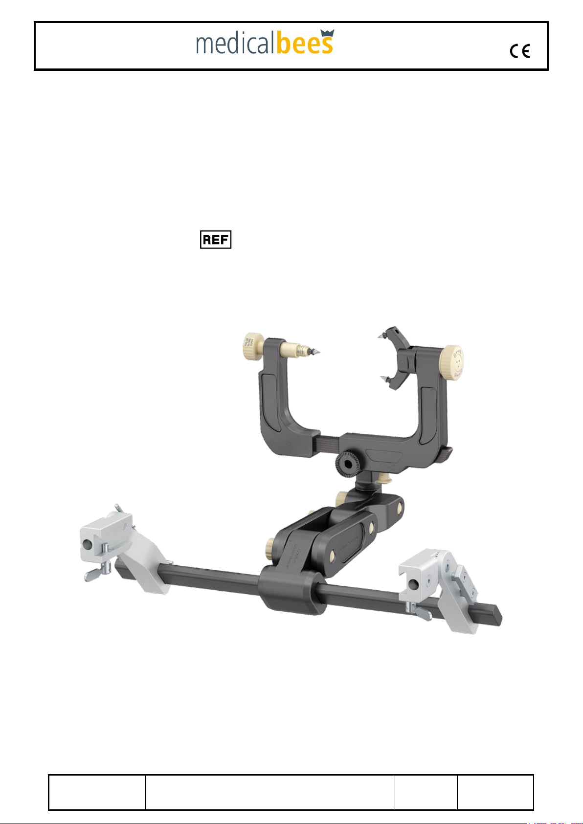
Instructions for Use
CT/ MRI compatible
MF-Headrest/ Cranial
Stabilization and Fixation System
MB1-17-20X-XX
Medical Bees GmbH
Friedrich-Wöhler-Straße 13
78576 Emmingen-Liptingen
Germany

0483
Date
21 October 2021
CT/ MRI compatible MF-System
IFU GA-008-02
Revision
01
Page
Seite 2von 37
Content
1Conformities..................................................................................................................5
1.1 Guidelines and norms.............................................................................................. 5
1.2 CE conformity.......................................................................................................... 5
2General Safety Information...........................................................................................5
2.1 Symbols used for safety information........................................................................ 5
2.2 Proper handling....................................................................................................... 6
2.3 Permitted user......................................................................................................... 6
3Basic Information..........................................................................................................6
3.1 Warranty and liability............................................................................................... 6
3.2 Obligations of the purchaser.................................................................................... 6
3.3 Obligations of the user ............................................................................................ 7
3.4 Usage as per instructions........................................................................................ 7
3.5 Improper usage....................................................................................................... 7
4Product description ......................................................................................................7
4.1 General description................................................................................................. 7
4.2 Components............................................................................................................ 8
Table adapter with connecting arm................................................................... 8
Swivel Adaptor................................................................................................. 9
Skull Clamp...................................................................................................... 9
Horseshoe.......................................................................................................10
4.3 Mounting of additional parts ...................................................................................10
4.4 Technical specifications .........................................................................................11
5Mounting......................................................................................................................16
5.1 Mounting of the Table adapter with connecting arm ...............................................16
5.2 Mounting to operating table, adjustments...............................................................16
5.3 Mounting of the Swivel Adaptor..............................................................................17
5.4 Mounting of the Skull Clamp...................................................................................17
5.5 Mounting of the Horseshoe ....................................................................................17
6Usage and Handling....................................................................................................18
6.1 Using the Table adapter with connecting arm.........................................................18
6.2 Using the Swivel Adaptor .......................................................................................18
6.3 Using the Skull Clamp............................................................................................18
6.4 Using the Horseshoe Headrest ..............................................................................19
6.5 Detailed description of application..........................................................................19
6.6 Set-Up/ Assembly/ Instructions for use for CT-System...........................................23
Connection to OR-table...................................................................................23

0483
Date
21 October 2021
CT/ MRI compatible MF-System
IFU GA-008-02
Revision
01
Page
Seite 3von 37
Connecting to Maquet OR-table (CT-/ MRI compatible system)......................25
Skull clamp......................................................................................................27
Horseshoe.......................................................................................................29
6.7 Function and safety inspections .............................................................................30
Before clinical use...........................................................................................30
After clinical use..............................................................................................30
7Care..............................................................................................................................31
7.1 Preparation for decontamination.............................................................................31
7.2 Pre-cleaning process..............................................................................................31
7.3 Cleaning / disinfection............................................................................................31
Manual cleaning process.................................................................................31
Automatic cleaning / disinfection process........................................................32
7.4 Inspections.............................................................................................................32
Maintenance and care of instruments..............................................................33
Packaging.......................................................................................................33
7.5 Sterilisation of skull clamp and swivel adapter........................................................33
7.6 Supplementary information.....................................................................................33
8Maintenance and Repair .............................................................................................35
8.1 Service, repairs and return shipment......................................................................35
Service and Repairs........................................................................................35
Return shipment..............................................................................................35
8.2 Maintenance intervals ............................................................................................35
8.3 Maintenance to be performed by the purchaser .....................................................36
9Environmentally Compatible Disposal.......................................................................36
10 Appendix......................................................................................................................37
10.1 Manufacturer information........................................................................................37
10.2 Authorized distributor .............................................................................................37

0483
Date
21 October 2021
CT/ MRI compatible MF-System
IFU GA-008-02
Revision
01
Page
Seite 4von 37
Preface
Dear reader,
These instructions for use provide information on the following
aspects of the Premium MF-Headrest System:
•safety
•mounting/ assembly
•usage
•maintenance
We continuously update our instruction manuals. Your suggestions
concerning this manual are welcome since they will help us make the
manual even more user-friendly. Please contact your authorized
distributor.
Storage:
This instruction manual contains important information on the safe, correct and efficient
usage of the Headrest System. Always keep this manual close to the device for easy
access and reference.

0483
Date
21 October 2021
CT/ MRI compatible MF-System
IFU GA-008-02
Revision
01
Page
Seite 5von 37
1 Conformities
1.1 Guidelines and norms
Description Guidelines and norms
MF- CT/ MRI compatible Headrest System COUNCIL DIRECTIVE 93/42/EEC
of 14 June 1993
1.2 CE conformity
The MF- CT/ MRI compatible Headrest System conforms to the basic requirements
of the applicable guideline and the corresponding norms of the Council of the
European Union.
2 General Safety Information
This instruction manual contains the basic information required for the safe usage of the
device.
2.1 Symbols used for safety information
The symbols explained below are used in this instruction manual to point out safety-
relevant information:
Danger:
This symbol indicates a danger to the health of the patient. Failure to observe this
information and follow the appropriate instructions may result in serious injury to the
patient and may even endanger the patient’s life.
Warning:
This symbol indicates a danger of injury to the user of the device.
Important:
This symbol indicates important information on the proper usage of the device. Failure
to observe this information and follow the appropriate instructions may cause damage
to the equipment.
Note:
This symbol provides tips concerning the usage of the device. Such information will
help you use the device to its full potential.

0483
Date
21 October 2021
CT/ MRI compatible MF-System
IFU GA-008-02
Revision
01
Page
Seite 6von 37
Exclusion of liability:
This symbol points out exclusions of liability of the manufacturer. Such disclaimers result
if the purchaser or user does not employ the device properly or fails to follow the
instructions.
You must carefully read, observe and follow the safety information furnished in this
instruction manual!
2.2 Proper handling
The device may only be used by trained staff.
2.3 Permitted user
The device may only be used and applied by specially trained persons belonging to the
operating team.
3 Basic Information
3.1 Warranty and liability
All warranty claims presuppose proper operation and treatment of the device. The
manufacturer guarantees that all parts are free from defects in both materials and
workmanship at the time of delivery.
Exclusion of liability:
The manufacturer shall not be liable for damages resulting from incorrect usage of
the device, failure to follow the instructions furnished in this manual or improper or
insufficient maintenance.
3.2 Obligations of the purchaser
The purchaser must ensure that all users of the Headrest System are trained in the
proper usage of the device and fully understand all safety-relevant information. The
purchaser shall document such training by means of a log and keep that log.
Exclusion of liability:
The manufacturer shall not be liable for damages resulting from the failure of the
purchaser to train the users of the device.
The purchaser shall be obliged to permit only trained staff, i.e. the operating team, to use
the device.
The purchaser shall also be responsible for storing this instruction manual in such a way
that it is always available when the device is being used.

0483
Date
21 October 2021
CT/ MRI compatible MF-System
IFU GA-008-02
Revision
01
Page
Seite 7von 37
3.3 Obligations of the user
All users of the device shall confirm in writing that they have read and fully understood
the safety information and the instructions contained in this manual
3.4 Usage as per instructions
The Headrest System is designed and built according to the latest technical
developments and to approved safety standards.
The Headrest System may be used
only as a support mechanism for head and neck surgery,
and only if the device is in a proper state as far as the safety aspects are concerned.
Usage as per instructions also implies
that you follow all information furnished in this manual
and that you clean and maintain the device as described
3.5 Improper usage
Improper usage or usage not conforming to the instructions contained in this manual may
result in serious injuries to the patient or the user and damage the device and other
equipment.
Exclusion of liability:
The manufacturer shall not be liable for damages resulting from improper usage. The
Headrest System can be mounted to all standard operating tables. The manufacturer
shall not be liable for damages resulting from the usage of the device in conjunction
with non-standardized operating tables.
4 Product description
4.1 General description
The MF- CT/ MRI compatible Headrest System is a mechanical support system which is
used in head and neck surgery. The connecting arm assembly with the transitional
member is mounted to the MF-Table adapter with connecting arm, which is mounted to
the operating table. The transitional member allows you to mount the Swivel Adaptor
which holds the Skull Clamp with the Skull Pins. This system allows the patient’s head to
be positioned and fixated for the operation.

0483
Date
21 October 2021
CT/ MRI compatible MF-System
IFU GA-008-02
Revision
01
Page
Seite 8von 37
4.2 Components
The CT-Headrest System consists of the following components:
Description:
Item-No.
Table adapter with connecting arm
MB1-17-200-31 +
MB1-17-200-15
Swivel Adaptor
MB1-17-200-26
or
(MB1-17-200-25)
Skull Clamp
Or
Horseshoe headrest
MB1-17-200-40
MB1-17-200-35
The system components consist of the following main parts:
Table adapter with connecting arm
•Operating table receptacle with
•1 connecting bar/rod
•2 end bracket, adjustable
•connecting arm assembly with locking lever
•transitional member
Fig. 1 Table adapter with clamp mount, general view

0483
Date
21 October 2021
CT/ MRI compatible MF-System
IFU GA-008-02
Revision
01
Page
Seite 9von 37
Swivel Adaptor
•swivel base
•two retaining ring units
•clamping screw 2x M24 1x M16
Skull Clamp
•Skull Clamp base
•Skull Clamp extension assembly torque screw with Skull
Pin holder (rotates 360 degrees)
Fig. 2 Swivel Adaptor, general view
Fig. 3 Skull Clamp, general view

0483
Date
21 October 2021
CT/ MRI compatible MF-System
IFU GA-008-02
Revision
01
Page
Seite 10 von 37
Horseshoe
•Horseshoe base
•clamping screw 2x M24 1x M16
4.3 Mounting of additional parts
We recommend using the following components with the Headrest System (refer
to instruction manual Skull Pins):
Description
Item number
Skull Pins stainless steel, Adult
MB1-17-000-50
Skull Pins stainless steel, Children
MB1-17-000-52
Skull Pins Titanium, Adult
MB1-17-000-54
Skull Pins Titanium, Children
MB1-17-000-56
Skull Pins PEEK + stainless steel, Adult
MB1-17-000-62
Skull Pins PEEK + stainless steel, Children
MB1-17-000-64
Skull Pins PEEK + Titanium, Adult
MB1-17-000-66
Skull Pins PEEK + Titanium, Children
MB1-17-000-68
Exclusion of liability:
The manufacturer shall not be liable for third-party components which are used in
conjunction with the MF- CT/ MRI compatible Headrest System.
Fig. 4 Horseshoe with gelpads
general view

0483
Date
21 October 2021
CT/ MRI compatible MF-System
IFU GA-008-02
Revision
01
Page
Seite 11 von 37
4.4 Technical specifications
Type of device: MF-CT Headrest System
Weight: Table adapter with connecting arm 6250 g
Swivel Adaptor 500 g
Skull Clamp 1700 g
Horseshoe 3450 g
Material PEEK, POM C
aluminum cast, stainless steel (table adapter)
Dimensions see outline drawing
The two end brackets of the Table adapter with connecting arm are equipped with an internal
isolation to prevent electrical stray currents when the Table adapter with connecting arm is
connected to the operating table.

0483
Date
21 October 2021
CT/ MRI compatible MF-System
IFU GA-008-02
Revision
01
Page
Seite 12 von 37
Fig. 6 Outline drawing Swivel Adaptor
Fig. 5 Outline drawing
Table adapter with clamp
mount

0483
Date
21 October 2021
CT/ MRI compatible MF-System
IFU GA-008-02
Revision
01
Page
Seite 13 von 37
Fig. 7 Outline drawing Skull Clamp

0483
Date
21 October 2021
CT/ MRI compatible MF-System
IFU GA-008-02
Revision
01
Page
Seite 14 von 37
Fig. 8 Outline drawing
Horseshoe

0483
Date
21 October 2021
CT/ MRI compatible MF-System
IFU GA-008-02
Revision
01
Page
Seite 15 von 37
Type of device: CT-/ MRI compatible Headrest System
Weight: Table adapter (Maquet) 2640 g
Skull Clamp 1700 g
Horseshoe 3450 g
Material PEEK, POM C
Dimensions see outline drawing
Fig. 9 Outline drawing Table adapter (Maquet)

0483
Date
21 October 2021
CT/ MRI compatible MF-System
IFU GA-008-02
Revision
01
Page
Seite 16 von 37
5 Mounting
5.1 Mounting of the Table adapter with connecting arm
To mount the Table adapter with connecting arm
1 Position the connecting arm assembly with the locking lever at the center of the
connecting bar/rod.
2 Place the adjustable end bracket onto the left end of the connecting tube.
3 Loosen the screws of the connecting arm
4 Connect the transitional member to the connecting arm assembly.
5 Fix the screws.
5.2 Mounting to operating table, adjustments
Mounting the Table adapter with connecting arm to the operating table:
1 Push the two end brackets into the appropriate receptacles of the operating table or
directly to OR rail
2 Proceed with step 4 if you do not need to adjust the Table adapter with connecting arm.
3 Adjust the left end bracket in such a way as to account for the distance between the
two holders at the operating table. Use the hex wrench which is located in the
connecting tube:
a) Loosen the adjustment screw at the left end bracket by means of the wrench
b) Turn the adjustment screw counterclockwise one full turn and carefully slide the end
bracket over the connecting tube to the desired position.
4 Turn the receptacle fastening screws at the operating table until fully tightened.
5 Position the adjustment screw of the left end bracket into the groove in the
connecting tube (otherwise, the Table adapter with connecting arm will not be rigid).
Carefully tighten the adjustment screw.
6 Move the connecting arm assembly to the desiredposition and fix the screws at
the connecting arm assembly.
Important:
The adjustable left end bracket allows you to easily mount the Table adapter with
connecting arm to standard operating tables.

0483
Date
21 October 2021
CT/ MRI compatible MF-System
IFU GA-008-02
Revision
01
Page
Seite 17 von 37
5.3 Mounting of the Swivel Adaptor
Mounting the Swivel Adaptor to the Table adapter with connecting arm:
Mount the Swivel adaptor to the transitional member of the Table adapter with
connecting arm
a) Screw the retaining ring at the transitional member and the retaining ring at
the Swivel Adaptortogether.
b) Fully tighten the clamping screw by turning it clockwise.
5.4 Mounting of the Skull Clamp
Mounting the Skull Clamp to the Swivel Adaptor:
1 Turn upper torque screw of Swivel Adaptor clockwise and position Skull Clamp as
desired.
2 Position the teeth at the Skull Clamp and Swivel Adaptor retaining rings in such a way
that they engage.
3 Tightly close the upper clamping screw.
5.5 Mounting of the Horseshoe
Mounting the Horseshoe headrest to Swivel Adaptor
1 Turn upper clamping screw of Swivel Adaptor clockwise and position Horseshoe
Headrest as desired.
2 Tightly close the upper clamping screw.
3 Turn the clamping screw counter clockwise in order to loosen the moving half of the
bottom part of the Horseshoe headrest. Move the half on the base rod until the
horseshoe has the desired size. Now tightly close the clamping screw in order to lock
the moving half of the horseshoe.
4 Open the corresponding locking lever in order to position the holder as required. You
may also remove it.
5 Make sure the gel pads are properly attached to the bottom part.
Danger:
Check all fastening screws at the device and the stability of the complete MF-System
before and after each clinical use.

0483
Date
21 October 2021
CT/ MRI compatible MF-System
IFU GA-008-02
Revision
01
Page
Seite 18 von 37
6 Usage and Handling
6.1 Using the Table adapter with connecting arm
The Table adapter with connecting arm is only designed for patient positioning in the
prone or supine positions.
6.2 Using the Swivel Adaptor
The Swivel Adaptor connects the Table adapter with connecting arm to the Skull
Clamp. The Swivel Adaptor may be rotated by 360 degrees. This allows for a fully
flexible adaptation of the position of the MF system to the patient’s position.
Adjusting the unit to the patient’s position:
1 Stabilize the patient’s head.
Carefully hold the Skull Clamp and the Swivel Adaptorin order to prevent the system from
losing itsstability.
2 Open the torque screw of the Swivel Adaptor.
3 Turn the Swivel Adaptor until you have obtained the desired position.
4 Lock the Swivel Adaptor torque screw by applying an adequate force/ pressure.
6.3 Using the Skull Clamp
The Skull Clamp is a component of the complete medical bees MF-System. It holds the
Skull Pins which enter the patient’s head. This allows a fully flexible adaptation of the
position of the MF-System to the patient’s position.
The Skull Clamp is attached to the patient’s head in two steps:
A Adjust the Table adapter with connecting arm, the Swivel adaptor and the
skull Clamp to the patient’s position.
B Fixate the patient’s head with the Skull Pins and the Skull Clamp.
C Locking and Unlocking the fixation of rocker arm.
Danger:
Always make sure to stabilize the patient’s head before adjusting the Swivel Adaptor.
Danger:
The maximum load for the skull clamp is 12.5 kgs/27.5 lbs. Please make sure to safely
position the patient’s neck and shoulders to avoid excess weight.

0483
Date
21 October 2021
CT/ MRI compatible MF-System
IFU GA-008-02
Revision
01
Page
Seite 19 von 37
6.4 Using the Horseshoe Headrest
The Horseshoe Headrest is one part of the complete system. It serves as a convenient
headrest for the patient during surgery in lateral or vertical positions.
The patient's head is fixated in several steps:
A Adjust the Base Unit and the Swivel Adaptor Horseshoe and the Horseshoe
Headrest to the patient's position.
B Adjust the Horseshoe Headrest to the size of the patient's head.
C Carefully place the patient's head on the Horseshoe Headrest.
D Mount the holder.
6.5 Detailed description of application
A Adjust the Table adapter with connecting arm, the Swivel Adaptor and the Skull
Clamp to the patient’s head position.
1 Open all fastening screws of all adjustable joints of the MF-System.
2 Position the patient’s head exactly as required for surgery.
3 Stabilize the patient’s head.
4 Carefully hold the Skull Clamp, the Swivel Locking Adaptor and the Skull Clamp
in order to prevent the system from losing its stability.
5 Insert the Skull Pins into the receptacles of the Skull Clamp (refer to
instruction manual Skull Pins)
Danger:
The maximum load for the Horseshoe headrest is 12.5 kgs / 27.5 lbs. Please make sure
to safely position the patient’s neck and shoulders to avoid excess weight.

0483
Date
21 October 2021
CT/ MRI compatible MF-System
IFU GA-008-02
Revision
01
Page
Seite 20 von 37
B Fixate the patient’s head with the Skull Pins and the Skull Clamp and ensure all
adjustable joints are then tightened and secured.
1 Adjusting the required Skull Clamp width:
Pull down on the knob (plunger) at the bottom of the Skull Clamp.
Open or close the extension assembly until you have obtained the desired width.
2 Adjust the Skull Clamp to the width of the patient’s head in such a way that the two
Skull Pins in the rocker arm are equidistant from the centerline of the head and the
single Skull Pin at the extension assembly is in line with this centerline.
3 Adjust the rocker arm to the desired position.
4 Turn the index knob from "Open" until it engages in the "Close" position. If this
cannot be done without problems, slightly turn the rocker arm until the index knob
engages.
5 Turn the torque screw in order to drive the Skull Pins at an angle of 90 degrees
into the patient’s head (refer to instruction manual Skull Pins, section mounting).
6 Ensure proper position of the Skull Pins.
7 Adjust the clamping force by means of the torque screw. The adjusted clamping
force is readable at the triangle in stages up to 360 N/80 lbs (maximum setting).
8 If necessary, readjust the clamping force. Turn the torque screw clockwise to
increase the clamping force.
Danger:
The user decides which type of fixation and what clamping force are required, based on the
thickness of the skull and the bone structure. Therefore: refer to the instruction manual Skull Pins.
Danger:
Failure to properly position the Skull Pins may cause serious injury to the patient. Therefore: avoid
the areas of the frontal sinus, temporal fossa, blood vessels or nerves.
Danger:
Angles other than 90 degrees may cause the system to become unstable and result
in serious injury to the patient.
Fig. 10 Attaching the Skull Clamp
Table of contents