MediSono P11 EXP User manual

User Manual
P11 EXP
Ultrasound System
Version 1.1

About This Manual
P/N: 4710.08923X01
4710.08923A08
Product Model: P11EXP
Statement
The manufacturer owns the intellectual property rights to this manual, and also maintains the contents of
this manual as confidential information. This manual is a reference to operation, maintenance or cleaning
for the product and does not convey any license under the patent rights of the manufacturer, nor the rights
of others.
This manual contains the information protected by copyrights or patents. Reproduction, amendment or
translation of this manual in any manner whatsoever without the written permission of the manufacturer is
strictly prohibited.
All information contained in this manual is believed to be correct. The manufacturer shall not be liable for
errors contained herein or for incidental or consequential damages in connection with the furnishing,
performance or use of this manual. The manufacturer does not assume any liability arising out of any
infringements of patents or other rights of third parties.
This manual is based on the maximum configuration and therefore some contents may not apply to your
product.
This manual is subject to change without prior notice and legal obligation.
Manufacturer’s Responsibility
The manufacturer is responsible for the effects on safety, reliability and performance of this product, only
if:
1
All installation operations, expansions, changes, modifications and repairs of this
product are conducted by the manufacturer authorized personnel;
2
The use or application of the product or the use of parts or accessories is approved by
the manufacturer.
3
The electrical installation of the relevant room complies with the applicable national and
local requirements; and
4
The product is used in accordance with the instructions for use.
Documentation
The manufacturer provides the documentation consisting of various manuals:
5
The basic user manual (this manual) describes the basic functions and operating
procedures of the system.

P11 EXP Portable Digital Color Doppler Ultrasound System
0-1
5 The advanced user manual provides information about the measurements and
calculations available in each mode.
6 Compact Disc (CD) provides the acoustic output data related to the system.
Signal words in this manual are defined as follows. Please understand their meanings clearly before reading
this manual.
Signal Word
Meaning
!
Indicates a potentially hazardous situation which, if not avoided, could
result in death or serious injury.
Indicates a potentially hazardous situation which, if not avoided, may
result in malfunction or damage of the system.
NOTE
Indicates precautions or recommendations that should be used in
operating the system.
Indicates a potentially biological hazardous situation which, if not avoided,
may result in disease transmission.
Boldface
d Word
Indicates keys and controls located on the control panel, or on-screen
objects such as menu items or keys.
Contact Information
Manufacturer: MEDISONO
Address: 3511 Silverside RD. Wilmington, DE 19810,United States

P11 EXP Portable Digital Color Doppler Ultrasound System
0-2

P11 EXP Portable Digital Color Doppler Ultrasound System
i
Contents
6
System Safetyand Maintenance 1-1
6.1
Safety Overview........................................................................................... 1-1
6.2
Description of Symbols and SignalWords Used...........................................1-2
6.2.1
Symbols........................................................................................... 1-2
6.2.2
Signal words.................................................................................... 1-4
6.3
Messages..................................................................................................... 1-4
6.4
Adverse Effects and Precautions..................................................................1-4
6.5
Biological Safety...........................................................................................1-5
6.6
Scanning Patients and Education.................................................................1-5
6.6.1
Safe Scanning Guideline................................................................. 1-6
6.6.2
Understanding the MI/TI Display...................................................... 1-7
6.7
Environmental Requirements.......................................................................1-11
6.8
Electrical Requirements ...............................................................................1-11
6.9
Electrical Safety............................................................................................1-12
6.10
Cautions for Using Accessories....................................................................1-13
6.11
Environmental Protection .............................................................................1-13
6.12
System Transportation.................................................................................1-14
6.12.1
Moving the System..........................................................................1-14
6.12.2
Transporting the System..................................................................1-14
7
System Specifications 2-1
7.1
Application and Contraindication..................................................................2-2
7.2
System Overview .........................................................................................2-2
7.3
Probes and Accessories...............................................................................2-4
7.4
Physical Specifications.................................................................................2-5
7.5
Concept of Operation...................................................................................2-5
7.5.1
Screen Layout ................................................................................. 2-5
7.5.2
Keyboard Layout ............................................................................. 2-6
7.5.3
Keyboard Description ...................................................................... 2-7
8
Starting the System 3-1
8.1
Probe Connection ........................................................................................ 3-1
8.2
Peripheral Device Connection......................................................................3-2
8.2.1
Connecting the Footswitch ..............................................................3-2
8.2.2
Connecting the Video Printer...........................................................3-2
8.2.3
Connecting the Network Printer andUSB Printer.............................3-3
8.3
Power On and Off......................................................................................... 3-4
8.3.1
Using AC Supply.............................................................................. 3-4
8.3.2
Using Battery................................................................................... 3-6
8.3.3
LED Indicators................................................................................. 3-7
8.4
General Operation Instructions.....................................................................3-8

P11 EXP Portable Digital Color Doppler Ultrasound System
iv
8.5
Patient Information....................................................................................... 3-9
8.6
Start Ultrasound Diagnosis ..........................................................................3-10
8.7
Customize applicationmode (Create New Exam Mode) ..............................3-10
8.8
Annotation and Bodymark............................................................................3-11
8.8.1
Annotation....................................................................................... 3-11
8.8.2
Bodymark........................................................................................ 3-11
8.9
Saving/Printing.............................................................................................3-12
9
System Setup 4-1
9.1
System Menu................................................................................................4-2
9.2
File Manager.................................................................................................4-2
9.2.1
Burn Data to CD/DVD..........................................................................4-3
9.3
Facility Name................................................................................................4-4
9.4
Set Date and Time........................................................................................4-4
9.5
System Information.......................................................................................4-4
9.6
System Setting..............................................................................................4-5
9.6.1
General Setting................................................................................4-5
9.6.2
Set Printer........................................................................................4-7
9.6.3
Set Calculation Menu.......................................................................4-7
9.6.4
Set Measurement Method................................................................4-8
9.6.5
Annotation Edit................................................................................4-10
9.6.6
Define Quick Key.....................................................................................4-11
9.6.7
Load Default.................................................................................... 4-12
9.6.8
DICOM Setting................................................................................ 4-14
10
B Mode 5-1
10.1
Starting B Mode............................................................................................5-2
10.2
B Mode Image Information............................................................................5-2
10.3
Real Time B Mode Operation....................................................................... 5-3
10.3.1
B Mode Menus.................................................................................5-3
10.3.2
ECG (Optional).................................................................................5-3
10.3.3
B Gain..............................................................................................5-4
10.3.4
Time Gain Compensation (TGC)......................................................5-4
10.3.5
Depth ...............................................................................................5-4
10.3.6
Focal Zones .....................................................................................5-5
10.3.7
Tissue Acoustic Characteristics........................................................5-6
10.3.8
Dynamic Range................................................................................5-6
10.3.9
Grayscale curve ...............................................................................5-7
10.3.10
Persistence......................................................................................5-7
10.3.11
Chroma............................................................................................5-7
10.3.12
Biopsy..............................................................................................5-7
10.3.13
Sector Width and Position................................................................5-8
10.3.14
Line Density .....................................................................................5-8
10.3.15
Compound Imaging..........................................................................5-9
10.3.16
Frequency Range.............................................................................5-9
10.3.17
Image Orientation.............................................................................5-9
10.3.18
Adaptive Image Fusion.................................................................... 5-10
10.3.19
uScan Function............................................................................... 5-10
10.3.20
Acoustic Output Power............................................................................5-10
10.3.21
TrapezoidalImaging ........................................................................5-10
10.3.22
2D Refresh...................................................................................... 5-11

P11 EXP Portable Digital Color Doppler Ultrasound System
iii
5.3.23 Zoom...............................................................................................5-11
6.4
B Cine Mode Operation................................................................................5-11
6.4.1
Grayscale curve...............................................................................5-11
6.4.2
Chroma............................................................................................5-12
6.4.3
Image Orientation (Left/Right)..........................................................5-12
6.4.4
Cine Review....................................................................................5-12
6.4.5
Select Image Sequence...................................................................5-12
6.4.6
Panoramic Imaging..........................................................................5-12
6.4.7
Cine Playback..................................................................................5-13
6.4.8
Saving Image/Cine..........................................................................5-13
6.5
Dual and QuadDisplay Formats...................................................................5-13
6.5.1
Dual Display Format........................................................................5-13
6.5.2
Quad Display Format.......................................................................5-15
6.6
Tissue Harmonic Imaging (THI)....................................................................5-15
7 CFM Mode 6-1
6.1
Starting CFM Mode........................................................................................6-2
6.2
Color Image Information...............................................................................6-2
6.3
Real Time CFMMode Operation....................................................................6-2
6.3.1
CFM Menus.......................................................................................6-2
6.3.2
Adjust CFM Sample Box....................................................................6-3
6.3.3
Pulse Repetition Frequency.............................................................6-3
6.3.4 Wall Filter . . . . . . . . . . . . . . . .
6.3.5 CFM Gain . . . . . . . . . . . . . . . .
6.3.6 Persistence . . . . . . . . . . . . . . .
6.3.7 Color Map . . . . . . . . . . . . . . . .
6.3.8 CFM Power . . . . . . . . . . . . . . .
6.3.9 Baseline . . . . . . . . . . . . . . . . .
6.3.10 Sector Width and Position . . . . . . . .
6.3.11 B Reject . . . . . . . . . . . . . . . . .
6.3.12
CFM Frequency . . . . . . . . . . . .
6.3.13
Image Orientation (Left/Right) . . . . . .
6.3.14 Flow Invert . . . . . . . . . . . . . . ..
6.3.15 Line Density . . . . . . . . . . . . . . .
6.3.16 2D Refresh . . . . . . . . . . . . . . .
6.4 CFM Cine Mode . . . . . . . . . .
6.4.1 C Map . . . . . . . . . .
6.4.2 B Reject . . . . . . . . .
6.4.3
Flow Invert . . . . . . . .
6.4.4
Cine Review . . . . . . .
6.4.5
Cine Playback . . . . . .
7 DPI Mode
7.1
Starting DPI Mode . . . . . . . .
7.2
DPI Image Information . . . . . . .
7.3
Real Time DPI Mode Operation . .
7.3.1
DPI Menus . . . . . . . .
7.3.2
Adjust DPI Sample Box .
7.3.3
Pulse Repetition Frequency
7.3.4
Wall Filter . . . . . . . .
7.3.5 DPI Gain . . . . . . . . .
. . . . . .
. . . . . .
. 6-3
. . . . . .
. . . . . . .
. 6-3
. . . . . .
. . . . . .
. 6-4
. . . . . .
. . . . . .
. 6-4
. . . . . .
. . . . . . .
. 6-4
. . . . . .
. . . . . .
. 6-5
. . . . . .
. . . . . .
. 6-5
. . . . . .
. . . . . .
. 6-5
. . . . . .
. . . . . . .
. 6-5
. . . . . .
. . . . . .
. 6-6
. . . . . .
. . . . . .
. 6-6
. . . . . .
. . . . . .
. 6-6
. . . . . .
. . . . . .
. 6-6
. . . . . . . . . . .
. . . . . . . . . . 6-6
. . . . . . . . . . . .
. . . . . . . . . 6-7
. . . . . . . . . . . .
. . . . . . . . . 6-7
. . . . . . . . . . . .
. . . . . . . . . 6-7
. . . . . . . . . . . .
. . . . . . . . . 6-7
. . . . . . . . . . . .
. . . . . . . . . 6-8
7-1
. . . . . . . . . . . .
. . . . . . . . . 7-1
. . . . . . . . . . .
. . . . . . . . . 7-2
. . . . . . . . . . .
. . . . . . . . . 7-2
. . . . . . . . . . . .
. . . . . . . . . 7-2
. . . . . . . . . . . .
. . . . . . . . . 7-2
. . . . . . . . . . .
. . . . . . . . . 7-3
. . . . . . . . . . . .
. . . . . . . . . 7-3
. . . . . . . . . . . .
... . . . . . . 7-3

P11 EXP Portable Digital Color Doppler Ultrasound System
iv
7.3.6
Persistence......................................................................................7-3
7.3.7
Color Map & Directional DPI.............................................................7-4
7.3.8
DPI Power..................................................................................................7-4
7.3.9
Sector Width and Position................................................................7-4
7.3.10
B Reject ...........................................................................................7-5
7.3.11
DPI Frequency.................................................................................7-5
7.3.12
Image Orientation (Left/Right)..........................................................7-5
7.3.13
Line Density .....................................................................................7-5
7.3.14
2D Refresh.......................................................................................7-5
7.4 DPI Cine Mode Operation.............................................................................7-6
7.4.1
Color Map.........................................................................................7-6
7.4.2
B Reject ...........................................................................................7-6
7.4.3
Cine Playback..................................................................................7-6
8 TDI Mode 8-1
8.1
Starting TDI Mode.........................................................................................8-2
8.2
TDI Image Information ................................................................................. 8-2
8.3
TDI Mode Operation .....................................................................................8-2
8.3.1
Real Time TDIMode Menus.............................................................8-2
8.3.2
Adjust TDI Sample Box ....................................................................8-2
8.3.3
Pulse Repetition Frequency .............................................................8-3
8.3.4
Wall Filter .........................................................................................8-3
8.3.5
TDI Gain...........................................................................................8-3
8.3.6
Persistence......................................................................................8-3
8.3.7
Color Map.........................................................................................8-4
8.3.8
TDI Power..................................................................................................8-4
8.3.9
Baseline...........................................................................................8-4
8.3.10
Sector Width and Position................................................................8-4
8.3.11
B Reject ...........................................................................................8-5
8.3.12
TDI Frequency .................................................................................8-5
8.3.13
Image Orientation (Left/Right)..........................................................8-5
8.3.14
Flow Invert........................................................................................8-5
8.3.15
Line Density .....................................................................................8-5
8.3.16
2D Refresh.......................................................................................8-6
8.4
Cine Mode Operation....................................................................................8-6
. . . . . . . . . . . . . . . . . . . . . . . . . 8-6
. . . . . . . . . . . . . . . . . . . . . . . . . 8-6
. . . . . . . . . . . . . . . . . . . . . . . . . 8-6
. . . . . . . . . . . . . . . . . . . . . . . . . 8-7
. . . . . . . . . . . . . . . . . . . . . . . . . 8-7
9 M Mode 9-1
9.1
Starting M Mode............................................................................................9-1
9.2
M Mode Operation, MTrace Inactive.............................................................9-1
9.2.1
Adjust M Mode Cursor Line..............................................................9-2
9.3
M Mode Operation, MTrace Active.............................................................. 9-3
9.3.1
M Gain .............................................................................................9-3
9.3.2
Sweep Speed...................................................................................9-3
9.3.3
Power.........................................................................................................9-4
9.3.4
Chroma............................................................................................9-4
9.3.5
M Process........................................................................................9-4
8.4.1
C Map . . . .
. .
8.4.2
B Reject . . .
. .
8.4.3
Flow Invert . .
. .
8.4.4
Cine Review .
. .
8.4.5
Cine Playback
. .

P11 EXP Portable Digital Color Doppler Ultrasound System
v
9.3.6
Video Invert ..................................................................................... 9-4
9.3.7
Steer M............................................................................................ 9-4
9.3.8
Display Format ................................................................................ 9-5
9.4
Cine Mode Operation...................................................................................9-5
10 Spectral Doppler Mode 10-1
10.1
Activation of SpectralDoppler Mode ............................................................10-2
10.1.1
B/CFM/DPI/TDI Operation in SpectralDoppler Mode....................... 10-3
10.1.2
2D Refresh......................................................................................10-3
10.1.3
Display Format ................................................................................10-3
10.2
PW Mode Operation.....................................................................................10-3
10.2.1
Sample VolumeGate Adjustment....................................................10-3
10.2.2
Activation of PW Spectral Display....................................................10-4
10.2.3
Pulse Repetition Frequency (PRF) ..................................................10-4
10.2.4
Wall Filter (WF)................................................................................10-4
10.2.5
Spectral Doppler Gain .....................................................................10-4
10.2.6
Steer Angle......................................................................................10-5
10.2.7
Flow Invert.......................................................................................10-5
10.2.8
Spectral Doppler Frequency............................................................10-5
10.2.9
Sweep Speed..................................................................................10-5
10.2.10
Baseline ..........................................................................................10-5
10.2.11
PW Power.................................................................................................10-6
10.2.12
Angle Correction..............................................................................10-6
10.2.13
Dynamic Range (DYN)............................................................................10-6
10.2.14
Chroma ...........................................................................................10-6
10.2.15
Video Invert.....................................................................................10-7
10.3
CW Mode Operation.....................................................................................10-7
10.3.1
Activation of CW Mode(PW ↔CW).........................................................10-7
10.3.2
CW Cursor Position.........................................................................10-7
10.3.3
Flow Invert.......................................................................................10-8
10.3.4
Sweep Speed..................................................................................10-8
10.3.5
CW Power.................................................................................................10-8
10.3.6
Dynamic Range (DYN)............................................................................10-8
10.3.7
Chroma............................................................................................10-8
10.3.8
Video Invert .....................................................................................10-8
10.3.9
Display Format ................................................................................10-8
10.3.10
Pulse Repetition Frequency (PRF)..................................................10-8
10.3.11
Wall Filter (WF)................................................................................10-8
10.4
Spectral Doppler Cine Mode Operation........................................................10-9
11 Triplex Mode 11-1
11.1
B+CFM/TDI+M.............................................................................................. 11-1
11.2
B+CFM/DPI/TDI+PW .................................................................................... 11-1
11.3
B+CFM/DPI+CW........................................................................................... 11-2
12 3D Mode 12-1
12.1 Starting 3D Mode . . . . . . . . . . . . . . . . . . . . . .
12.2 3D Mode Menus . . . . . . . . . . . . . . . . . . . . . . .
12.3 3D Mode Operation . . . . . . . . . . . . . . . . . . . . .
12.3.1 Display Format . . . . . . . . . . . . . . . . . . .
12.3.2
Manual Rotate and Zoom . . . . . . . . . . . . . .
. . . . .
. . 12-1
. . . . .
. . 12-2
. . . . .
. . 12-3
. . . . .
. . 12-3
. . . . .
. . 12-3

P11 EXP Portable Digital Color Doppler Ultrasound System
vi
12.3.3
Auto Rotate..................................................................................... 12-4
12.3.4
Render Mode .................................................................................. 12-4
12.3.5
Trace Cut......................................................................................... 12-4
12.3.6
Clip Plane........................................................................................ 12-4
12.3.7
Opacity Setting................................................................................12-5
12.3.8
Multi-Slice ....................................................................................... 12-5
12.3.9
Slice Spacing ..................................................................................12-5
12.3.10
Color Map........................................................................................ 12-5
12.3.11
Scan Method................................................................................... 12-5
12.3.12
Z Scale (For Scan Method=
Lin
)........................................................................12-5
12.3.13
Z Angle (For Scan Method= Sec).........................................................................12-5
13 4D Mode 13-1
13.1
Starting 4D Mode......................................................................................... 13-1
13.2
4D Mode Menus...........................................................................................13-2
13.3
4D Mode Operations....................................................................................13-3
13.3.1
Display Format................................................................................ 13-3
13.3.2
Adjustment of Sample Box & CutOff Line....................................... 13-3
. . . . . . . . . . . . . . 13-4
. . . . . . . . . . . . . . 13-4
. . . . . . . . . . . . . . 13-4
. . . . . . . . . . . . . . 13-4
. . . . . . . . . . . . . . 13-4
. . . . . . . . . . . . . . 13-4
14 Probes 14-1
14.1
Probe........................................................................................................... 14-1
14.1.1
Available Probes.............................................................................14-1
14.1.2
Probe Usage................................................................................... 14-1
14.1.3
Cleaning the Probe..........................................................................14-2
14.1.4
Disinfecting or Sterilizingthe Probe.................................................14-2
14.1.5
Disinfecting and Sterilizing theProbe Cable.................................... 14-4
14.1.6
Storage and Transportation.............................................................14-5
15 System Maintenance 15-1
15.1
Manufacturer Responsibility.........................................................................15-1
15.2
Cleaning the System....................................................................................15-1
15.3
Maintenance Checks ...................................................................................15-2
15.4
Backup......................................................................................................... 15-3
15.5
Troubleshooting................................................................................................15-3
15.6
Equipment Disposal.....................................................................................15-3
15.7
Service Information......................................................................................15-4
A
EMC Guidance and Manufacturer’s Declaration
A-1
B
In Situ, Derated, and Water Value Intensities
B-1
C
Principle for Using Acoustic Power
C-1
13.3.3
Sweep Angle . . .
. .
. .
. .
. .
. .
13.3.4
Cine Review . . . .
. .
. .
. .
. .
. .
13.3.5
Rescan . . . . . .
. .
. .
. .
. .
. .
13.3.6
Image Quality . . .
. .
. .
. .
. .
. .
13.3.7
Stabilization . . . .
. .
. .
. .
. .
. .
13.3.8
Volume Review . .
. .
. .
. .
. .
. .

1-11
Chapter 1
System Safety and
Maintenance
1.1
Safety Overview
This section discusses measures to ensure the safety of both the operator and patient.
To ensure the safety of both operator and patient, please read the relevant details in this
chapter carefully before operating this system. Disregarding the WARNINGS or violation of
relevant rules may result in personal injury or even loss of life for operator or patient.
Users should observe the following PRECAUTIONS:
•
Thissystem complies withTypeBFgeneral equipment, andtheIEC60601-1standard.
•
Do not modify this system in any way.Necessary modifications must be made only
by the manufacturer or its designatedagents.
•
This system has been fully adjusted at the factory. Do not adjust any fixed adjustable
parts.
•
Not to position this equipmentto make it difficult to operate the disconnection device.
•
In the event of a malfunction, turn off the system immediately and inform the manu-
facturer or its designatedagents.
•
Thepowercableof thesystem should onlybe connected to a grounded powersocket.
Do not remove the ground cable for any reason.
•
Only connect this system, either electronically or mechanically, with devices that
comply with the IEC60601-1 standard. Recheck the leakage current and other safety
performance indices of the entire system to avoid potential system damage caused
by leakage from a currentsuperposition.
•
The system does not incorporate any specialized protective measures in the event
it is configured with high-frequency operation devices. The operator should use
CAUTION in these types ofapplications.
•
The system should be installed only by personnel authorized by the manufacturer.
Do not attempt to install the systemyourself.
•
Only an authorized service engineer may perform maintenance.
•
Only a qualified operator, or someone under qualified supervision, should use the
system.

P11 EXP Portable Digital Color Doppler Ultrasound System
1-2
General warning sign
•
Do not use this system in the presence of flammable substances or an explosion
may occur.
•
Donotcontinuouslyscanthesamepartofapatientorexposethepatienttoprolonged
scanning. Doing so may harm thepatient.
•
When using the system for ultrasound testing, use only qualified ultrasound gel that
complies with systemstandards.
•
Do not use the switch at the back of the unit for normal shut down. Always use the
power-on button in the keyboardarea
•
Do not unplug any probe when the system is in real time mode. Doing so may
damage the probe. Freeze the scan or enter preparation mode (EXAM) screen
before disconnection.
•
To prevent from arm or neck injury, the operator should not stay at the same position
for too long during patient scanning without taking break.
•
Do not put liquid on top of the mainunit.
•
Do not place other objects on top of the control panel. Do not sleep or sit on the
control panel or other part of the ultrasoundsystem.
•
There is a cleared list of sterilants and high-level disinfectants for use in processing
reusablemedicalanddentaldevicesonFDAwebsite.Thatlistcanbeconsultedtofind
agentsthatmaybeuseful for probedisinfection.Pleasereferto the following URLfor
FDA-Cleared Sterilants and High Level Disinfectants: http://www.fda.gov/MedicalDevices
/DeviceRegulationandGuidance/ReprocessingofSingle-UseDevices/ucm133514.htm.
•
Do not knock or shake thesystem.
•
Connect the earth conductor only before powering on the system. Disconnect the
grounding cable only after powering off the system. Otherwise, there is a danger of
electric shock.
•
In the environment that patient is 1.8 meters (6 feet) around, connect peripherals
to the auxiliary power outlet which is capable of isolation protection, or power the
peripherals by auxiliary output cable or isolation transformer complied with IEC
60601-1 or the power input of the same safety level.
•
Leaveatleast20cmatthebackandbothsidesoftheultrasoundsystemforventilation.
Otherwise, the temperaturerise could cause failures.
•
For proper disposal of this product, please contact our service department.
1.2
Description of Symbols and Signal Words Used
1.2.1
Symbols
The following symbols are utilized on the product or the label and package thereof.
Symbol Description
Caution

P11 EXP Portable Digital Color Doppler Ultrasound System
1-3
Symbol
Meaning
Pinch hazard
Risk of explosion if used in the presence of flammable
anesthetics
Type BF Applied Part
Main switch OFF
Main switch ON
On/Standby switch
Footswitch Connector
Protective earth (ground)
Equipotentiality
Alternating current
Degree of IP protection
Non-ionizing electromagnetic radiation.
Manufacturer
Date of manufacture
Follow instructions for use
Network Port
USB Port

P11 EXP Portable Digital Color Doppler Ultrasound System
1-4
This symbol indicates that waste electrical and electronic equipment must not be disposed of
as unsorted municipal waste and must be collected separately. Please contact an authorized
representative of the manufacturer for information concerning the decommissioning of your
equipment.
1.2.2
Signal words
The following signal words are used throughout the user manual.
Symbol Description
Note Follow these instructions to obtain additional helpful information.
1.3
Messages
All the messages generated by this ultrasound system are self-explanatory. However, you
may encounter the following situations.
License renewal
When the validity of the license is less than 10 days, the message on the above right
will appear on the preparation mode (EXAM) screen. System function will not be
affected until the license is expired. When the license has been expired, the message
on the above left will appear when the user clicks an application mode icon. Please
contact our representative for license renewal.
Auto quit ultrasound scan
In order to protect the operator or the patient from accidentally receiving excessive
acoustic energy, the system automatically stops the real time scan (no on-screen
messagewillbeprovided)andreturnsthepreparationmodeiftherehasbeennouser
activity for 30 minutes. The user may resume the scan from the preparation mode.
No prerequisite action before another ultrasound scan is required.
1.4
Adverse Effects and Precautions
This ultrasound system, same as all other diagnostic ultrasound system in the market,
should be used only for clinically appropriate reasons, for the shortest period of time and
at power settings as low as reasonably achievable (ALARA). The American Institute of
Ultrasound in Medicine (AIUM) principle of As Low As Reasonably Achievable (ALARA)
is recommended during selection of the output of ultrasound power. Try not to aim probe
at the same spot in tissue for a long period of time unless it is necessary for diagnostic
purpose. Do not scan the fetal in the Doppler mode for a long time. Freeze the image any
Caution! Follow these instructions to avoid system damage.
Indoor use only.
Warning! Follow these instructions to avoid personal injury or system damage.

P11 EXP Portable Digital Color Doppler Ultrasound System
1-5
time when the transducer is not used. This system, as a basic imaging system with the
Doppler and Color Doppler feature generates acoustic power that is below pre-enactment
levels, which are generally considered to be safe for the respective applications.
1.5
Biological Safety
This product, as with all diagnostic ultrasound equipment, should be used only for valid
reasons and should be used both for the shortest period of time and at the lowest power
settings necessary ( ALARA - As LowAs Reasonably Achievable) to produce diagnostically
acceptable images.
The AIUM offers the following guidelines:
Clinical Safety Quoted from AIUM
Approved March 26, 1997
Diagnostic ultrasound has been in use since the late 1950s. Given its
known benefits and recognized efficacy for medical diagnosis, including use
during human pregnancy, the American Institute of Ultrasound in Medicine
herein addresses the clinical safety of such use:
There are no confirmed biological effects on patients or instrument oper-
ators caused by exposures from present diagnostic ultrasound instruments.
Although the possibility exists that such biological effects may be identified in
the future, current data indicate that the benefits to patients of the prudent use
of diagnostic ultrasound outweigh the risks, if any that may be present.
Heating:
Elevating tissue temperature during obstetrical examinations creates medical concerns. At
the embryo development stage, the rise in temperature and the length of time exposed to
heat combine to determine potential detrimental effects. Exercise CAUTION particularly
during Doppler/Colorexams.
The Thermal Index (TI) provides a statistical estimate of the potential temperature elevation
(in centigrade) of tissue temperature. Three forms of TI are available: TIS, for soft tissue
exposures; TIB, for instances when bone lies near the beam focus; and TIC, for the heating
of bone situated close to thetransducer.
Cavitation:
Cavitation may occur when sound passes through an area that contains a cavity, such as
a gas bubble or air pocket (in the lung or intestine, for example). During the process of
cavitation, the sound wave may cause the bubble to contract or resonate. This oscillation
may cause the bubbles to explode and damage the tissue. The Mechanical Index (MI) has
been created to help users accurately evaluate the likelihood of cavitation and the related
adverse effects.
1.6
Scanning Patients and Education
The Track-3 or IEC60601-2-37 output display standard allows users to share the respon-
sibility for the safe use of this ultrasound system. Follow these usage guidelines for safe
operation:
•
Inordertomaintainpropercleanlinessofthetransducers,alwayscleanthembetween
patients.
•
Always use a new disinfected sheath on all EV/ER probes during every exam.

P11 EXP Portable Digital Color Doppler Ultrasound System
1-6
•
Continuously move the probe, rather than staying in a single spot, to avoid elevated
temperatures in one part of the patient’sbody.
•
Move probe away from the patient when not activelyscanning.
•
Understand the meaning of the TI, TIS, TIB, TIC, and MI output display, as well as
the relationship between these parameters and the thermal/cavitation bioeffect to the
tissue.
•
Expose the patient to only the very lowest practical transmit power levels for the
shortest possible time to achieve a satisfactory diagnosis (ALARA - As Low As
Reasonably Achievable).
1.6.1
Safe Scanning Guideline
1.
Ultrasound should only be used for medical diagnosis and only by trained medical
personnel.
2.
Diagnostic ultrasound procedures should be done only by personnel fully trained in
the use of the equipment, in the interpretation of the results and images, and in the
safe use of ultrasound (including education as to potential hazards).
3.
Operators should understand the likely influence of the machine controls, the op-
erating mode (e.g. B-mode, color Doppler imaging or spectral Doppler) and probe
frequency on thermal and cavitationhazards.
4.
Select a low setting for each new patient. Output should only be increased during the
examination if penetration is still required to achieve a satisfactory result, and after
the Gain control has been moved to its maximum value.
5.
Maintain the shortest examination time necessary to produce a useful diagnostic
result.
6.
Do not hold the probe in a fixed position for any longer than is necessary. It should be
removed from the patient whenever there is no need for real-time imaging or spectral
Doppler acquisition. The freeze frame and Cine loop capabilities allow images to be
reviewed and discussed without exposing the patient to continuous scanning.
7.
Do not use endo-cavity probes if there is noticeable self heating of the probe when
operating in the air. Although applicable to any probe, take particular care during
trans-vaginal exams during the first eight weeks of gestation.
8.
Take particular care to reduce output and minimize exposure time of an embryo or
fetus when the temperature of the mother is already elevated.
9.
Takeparticular care to reduce the risk of thermal hazard during diagnostic ultrasound
when exposing: an embryo less than eight weeks after gestation; or the head, brain
or spine of any fetus orneonate.
10.
Operatorsshouldcontinuallymonitortheon-screenthermalindex(TI)andmechanical
index(MI) values and use control settings that keep these settings as low as possible
while still achieving diagnostically usefulresults.
In obstetric examinations, TIS (soft tissue thermal index) should be monitored during
scans carried outin the first eight weeks after gestation, and TIB (bone thermal index)
thereafter. In applications where the probe is very close to bone (e.g. trans-cranial
applications), TIC (cranial thermal index) should be monitored.

P11 EXP Portable Digital Color Doppler Ultrasound System
1-7
MI>0.3There
is
a
possibilityof
minor
damage
to neonatallungor
intestine.If
such
exposure
is
necessary,reducetheexposuretime
as muchas
possible.
MI>0.7There
is
a
riskof
cavitation
if
an
ultrasoundcontrastagent
containing
gas
micro-spheres
is
beingused.There
is
a
theoretical
riskof cavitationwithoutthepresenceof ultrasound contrast
agents.
The
risk
increaseswith
MI
values
above
this
threshold.
TI>0.7The
overa
l
exposuretimeof anembryoorfetusshouldbe
restrictedin
accordancewithTable1.1belowasa reference.
TI
Maximum exposure time (minutes)
0.7
60
1.0
30
1.5
15
2.0
4
2.5
1
Table 1.1: Maximum recommended exposure times for an embryo or fetus
11.
Non-diagnostic use of ultrasound equipment is not generally recommended. Ex-
amples of non-diagnostic uses of ultrasound equipment include repeated scans for
operatortraining,equipmentdemonstration usingnormalsubjects, andtheproduction
of souvenir pictures or videos of afetus.
For equipment of which the safety indices are displayed over their full range of values,
the TI should always be less than 0.5 and the MI should always be less than 0.3.
Avoid frequent repeated exposure of anysubject.
Scans inthe first trimester of pregnancy should not becarried out for the sole purpose
of producing souvenir videos or photographs, nor should their production involve
increasing the exposure levels or extending the scan times beyond those needed for
clinical purposes.
12.
Diagnostic ultrasound has the potential for both false positive and false negative
results. Misdiagnosis is far more dangerous than any effect that might result from the
ultrasound exposure. Therefore, diagnostic ultrasound should be performed only by
those with sufficient training andeducation.
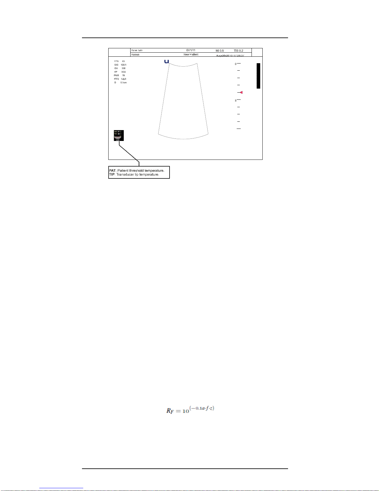
1.6.1.1 Temperature Display for Transducers Intended for Internal Use
For transducers intended for internal applications, for example the intracavitary or trans-
esophageal transducers, the transducer tip temperature is displayed on the screen. Refer
to Figure 1.1 for the location of the temperature display. To protect the patient against the
harm of excessive temperature, the system automatically turns off the transducer when the
temperature of the transducer reaches a threshold temperature, which is adjustable and
has a maximum value of 43◦C.
1.6.2 Understanding the MI/TI Display
Track-3 follows the Output Display Standard for systems which include fetal Doppler appli-
cations. The acoustic output will not be evaluated on an application-specific basis, but the
global maximum de-rated Ispta must be
≤
720 mW/cm2 and either the global maximum MI
must be
≤
1.9 or the global maximum de-rated Isppa must be
≤
190 W/cm2. An exception
is for ophthalmic use, in which case the TI=max (TIS_as, TIC) is not to exceed 1.0; Ispta.3
P11 EXP Portable Digital Color Doppler Ultrasound System
1-8
Figure 1.1: Transducer tip temperature display
≤
50mW/cm2,andMI
≤
0.23.Track-3givestheuserthefreedomtoincreasetheoutput
acoustic power for a specific exam, and still limit output acoustic power within the global
maximumde-ratedIspta
≤
720mW/cm2underanOutputDisplayStandard.
Foranydiagnostic ultrasonic systems, Track-3 provides anOutput Indices DisplayStandard.
The diagnostic ultrasound systems and its operator’s manual contain the information
regarding an ALARA (As Low As Reasonably Achievable) education program for the clinical
end-user and the acoustic output indices, MI and TI.
The MI describes the likelihood of cavitation, and the TI offers the predicted maximum
temperature rise in tissue as a result of the diagnostic examination.
In general, a temperature increase of 2.5 ◦C must be present consistently at one spot for 2
hours to cause fetal abnormalities. Avoiding a local temperature rise above 1 ◦C should
ensure that no thermally induced biologic effect occurs.
When referring to the TI for potential thermal effect, a TI equal to 1 does not mean the
temperature will rise 1 degree C. It onlymeans an increased potential for thermal effects can
be expected as the TI increases. A high index does not mean that bioeffects are occurring,
but only that the potential exists and there is no consideration in the TI for the scan duration,
so minimizing the overall scan time will reduce the potential for effects. These operator
control and display features shift the safety responsibility from the manufacturer to the user.
So it is very important to have the Ultrasound systems display the acoustic output indices
correctly and the education of the user to interpret the value appropriately.
RF: De-rating factor
In Situ intensity and pressure cannot currently be measured. Therefore, the acoustic power
measurement is normally done in the water tank, and when soft tissue replaces water along
the ultrasound path, a decrease in intensity is expected. The fractional reduction in intensity
caused by attenuation is DENOTED by the de-rating factor RF,
Where a is the attenuation coefficient in dB cm-1 MHz-1, f is the transducer center
frequency, and z is the distance along the beam axis between the source and the
point of interest.
De-rating factor RF for the various distances and frequencies with attenuation coefficient

P11 EXP Portable Digital Color Doppler Ultrasound System
1-9
0.3dB cm-1 MHz-1 in homogeneous soft tissue is listed in the following table. An example
is if the user uses 7.5MHz frequency, the power will be attenuated by .0750 at 5cm, or
0.3x7.5x5=-11.25dB. The De-rated Intensity is also referred to as ’.3’ at the end (e.g.
Ispta.3).
Distance Frequency (MHz)
(cm)
1
3
5
7,5
1
0,9332
0,8128
0,7080
0,5957
2
0,8710
0,6607
0,5012
0,3548
3
0,8128
0,5370
0,3548
0,2113
4
0,7586
0,4365
0,2512
0,1259
5
0,7080
0,3548
0,1778
0,0750
6
0,6607
0,2884
0,1259
0,0447
7
0,6166
0,2344
0,0891
0,0266
8
0,5754
0,1903
0,0631
0,0158
I’=I*RF Where I’ is the intensity in soft tissue, I is the
time-averaged intensity measured in water.
Tissue Model
Tissue temperature elevation depends on power, tissue type, beam width, and scanning
mode. Six models are developed to mimic possible clinical situations.
Thermal
Models
Composition
Mode
Specification
Typ. app
1TIS
Soft tissue
Unscanned
Large aperture
(>1cm )
Liver PW
2TIS
Soft tissue
Unscanned
Small aperture
(<1cm )
Pencil probe
3TIS
Soft tissue
Scanned
Evaluated at surface
Breast color
4TIB
Soft tissue and
Scanned
Soft tissue at surface
Muscle color
bone
5TIB
Soft tissue and
Unscanned
Bone at focus
Fetus head PW
bone
6TIC
Soft tissue and
Unscanned / Scanned
Bone at surface
Trans cranial
bone
Soft tissue
Describes low fat content tissue that does not contain calcifications or large gas-filled
spaces.
Scanned: (auto-scan)
Refers to the steering of successive burst through the field of view, e.g. B and color mode.
UnScanned
Emissionof ultrasonic pulses occurs along a single line of sight and is unchangeduntil the
transducer is moved to a new position. For instance, the PW,CW and M mode.
TI
TI is defined as the ratio of the In Situ acoustic power (W.3) to the acoustic power required
to raise tissue temperature by 1oC (Wdeg),
Three TIs corresponding to soft tissue (TIS) for abdominal; bone (TIB) for fetal and neonatal
cephalic; and cranial bone (TIC) for pediatric and adult cephalic, have been developed for
applications in differentexams.

P11 EXP Portable Digital Color Doppler Ultrasound System
1-10
An estimate of the acoustic power in milliwatts necessary to produce a 1◦C temperature
elevation in soft tissue is:
for model 1 to 4, where fc is the center frequency in MHz.
for model 5 and 6, where K (beam shape factor) is 1.0, D is the aperture diameter in
cm at the depth of interest
MI
Cavitation is more likely to occur at high pressures and low frequencies in pulse ultrasound
wave in the tissue, which contains the bubble or air pocket (for instance, the lung, intestine,
or scan with gas contrast agents). The threshold under optimum conditions of pulsed
ultrasound is predicted bythe ratio of thepeakpressure to thesquarerootof the frequency.
Pr’ is the de-rated (0.3) peak rare-fractional pressure in Mpa at the point where PII is
the maximum, and fc is the center frequency in MHz. PII is the Pulse Intensity Integral
that the total energy per unit area carried by the wave during the time duration of the
pulse.
The peak rare-fractional pressure is measured in hydrophone maximum negative volt-
age normalized by the hydrophone calibration parameter.
Display Guideline
For differentoperation modes,different indicesmust be displayed. However, onlyone index
needs to be shown at a time. Display is not required if maximum MI is less than 1.0 for
any setting of the operating mode, or if maximum TI is less than 1.0 for any setting of the
operating mode. For TI, if the TIS and TIC are both greater than 1.0, the scanners need not
be capableofdisplaying bothindicessimultaneously. If the indexfalls below0.4, nodisplay
is needed. The display increments are no greater than 0.2 for index value less than one
and no greater than 1.0 for index values greater than one (e.g. 0.4, 0.6, 0.8, 1, 2, 3).
Display and Report in Different Mode
For B-Scan Mode
Only display and report MI, and start from 0.4 if maximum MI > 1.0
For Color Mode
Only display and report TIS or TIB and start from 0.4 if maximum TI > 1.0
For Doppler Mode
Only display and report TIS or TIB and start from 0.4 if maximum TI > 1.0
Below is a simple guideline for the user when TI exceeds one limit exposure time to 4(6-TI)
minutes based on the National Council on Radiation Protection. Exposure Criteria for
Medical Diagnostic Ultrasound: I. Criteria Based on Thermal Mechanisms. Report No.113
1992:
Operator Control Features
The user should be aware that certain operator controls may affect the acoustic output. It is
recommended to use the default (or lowest) output power setting and compensate using
Gain control to acquire an image. Other than the output power setting in the soft-menu,
which has the most direct impact on the power; the PRF, image sector size, frame rate,
depth, and focal position also slightly affect the output power. The default setting is normally
around 70% of the allowable power depending on the exam icon.
Table of contents
Other MediSono Diagnostic Equipment manuals


