Wohler VIS 700 User manual

Technik nach Maß
EN
NL
Bedienungsanleitung
Zusatzbeleuchtung 26/40
Manual
Light Ring 26/40
Mode d’emploie
Eclairage LED 26/40
Bedieningshandleiding
Verlichtingsring steekbaar 26/40
Wöhler VIS 700
Best.- Nr. 24529 2019-04-24

Inhalt
2
Inhalt
1Allgemeines...........................................3
1.1 Informationen zur Bedienungsanleitung........ 3
1.2 Hinweise in der Bedienungsanleitung ........... 3
1.3 Bestimmungsgemäße Verwendung .............. 4
1.4 Entsorgung.................................................... 4
1.5 Herstelleranschrift ......................................... 4
1.6 Wichtiger Hinweis.......................................... 4
2Technische Daten .................................5
3Montage der Zusatzbeleuchtung.........5
4Einstellung der Beleuchtung...............6
4.1 Systemvorrausetzungen der Kamera............ 6
4.2 Einstellung der Beleuchtung.......................... 6
5Garantie und Service............................7
5.1 Garantie ........................................................ 7
5.2 Service .......................................................... 7
6Konformitätserklärung .........................8

Allgemeines
3
1 Allgemeines
1.1 Informationen zur Be-
dienungsanleitung
Diese Bedienungsanleitung ermöglicht Ihnen die
sichere Bedienung der Wöhler Zusatzbeleuch-
tung. Bewahren Sie diese Bedienungsanleitung
dauerhaft auf.
Die Zusatzbeleuchtung darf grundsätzlich nur von
fachkundigem Personal für den bestimmungsge-
mäßen Gebrauch eingesetzt werden.
Für Schäden, die aufgrund der Nichtbeachtung
dieser Bedienungsanleitung entstehen, überneh-
men wir keine Haftung.
1.2 Hinweise in der Bedie-
nungsanleitung
ACHTUNG!
Kennzeichnet Hinweise auf Gefahren, die Be-
schädigungen des Geräts zur Folge haben kön-
nen.
HINWEIS!
Hebt Tipps und andere nützliche Informationen
hervor.

Allgemeines
4
1.3 Bestimmungsgemäße
Verwendung
Die Zusatzbeleuchtung wird zum Ausleuchten
dunkler, staubiger oder verrußter Umgebung wäh-
rend der Inspektion mit dem Kamerasystem Wöh-
ler VIS 700 eingesetzt.
Die Zusatzbeleuchtung 26/40 ist mit dem steck-
baren Wöhler Kamerakopf Ø 26 und 40 mm zu
nutzen. Sie wird zwischen Kamerakopf und Ka-
merastange bzw. Kamerakabel angebracht. Das
Dimmen erfolgt über das Wöhler VIS 700 Vi-
deoinspektionssystem.
1.4 Entsorgung
Elektronische Geräte dürfen nicht im Hausmüll
entsorgt werden, sondern müssen gemäß den
geltenden Umweltvorschriften entsorgt werden.
Schadhafte Akkus gelten als Sondermüll und
müssen zur Entsorgung in den vorgesehenen
Sammelstellen abgegeben werden.
1.5 Herstelleranschrift
Wöhler Technik GmbH
Wöhler-Platz 1
33181 Bad Wünnenberg
Tel.: +49 2953 73-100
Fax: +49 2953 73-96100
E-Mail: info@woehler.de
1.6 Wichtiger Hinweis
ACHTUNG!
Die Zusatzbeleuchtung ist nur wasserdicht nach
IP 67, wenn sie wie im Folgenden
beschrieben mit
der Stange und dem Kamerakopf verbunden ist.
Sie darf keinesfalls ohne Kamerakopf und Stange
mit Wasser gereinigt werden.

Technische Daten
5
2 Technische Daten
Beschreibung
Angabe
Anschluss
5 polige Steckverbin-
dung
Beleuchtung
16 weiße LEDs
Dichtheitsklasse
(nur mit angeschlos-
sener Stange und
angeschlossenem
Kamerakopf)
wasserdicht nach IP 67
Ein-/Ausschalten
Über Kamerasystem
Wöhler VIS 700
Stromversorgung
Über Kamerasystem
Wöhler VIS 700
3 Montage der Zusatzbeleuchtung
•Schrauben Sie den Kamerakopf von der Ka-
merastange ab.
Abb. 1: Zusatzbeleuchtung auf
Kamerastange gesteckt
•Stecken Sie den 5-poligen Stecker der Kame-
rastange oder des Kamerakabels in die Buch-
se der Wöhler Zusatzbeleuchtung.
•Drehen Sie das Gewindestück an der Kame-
rastange zum Verschließen nach rechts.
Abb. 2: Zusatzbeleuchtung kom-
plett montiert
•Stecken Sie den Anschluss des Kamerakopfes
auf den Stecker der Zusatzbeleuchtung und
drehen Sie, bis die Pole einrasten.
•Drehen Sie das Gewindestück an der Kame-
rastange zum Verschließen nach rechts.

Einstellung der Beleuchtung
6
4 Einstellung der Beleuchtung
Die Helligkeit der Zusatzbeleuchtung kann über
die Kamera gesteuert werden.
4.1 Systemvorrausetz
ungen der Kamera HINWEIS!
Das Ein-/Ausschalten der Zusatzbeleuchtung ist
bei einer älteren Version der Kamera oder des
Kamerakopfes nicht möglich.
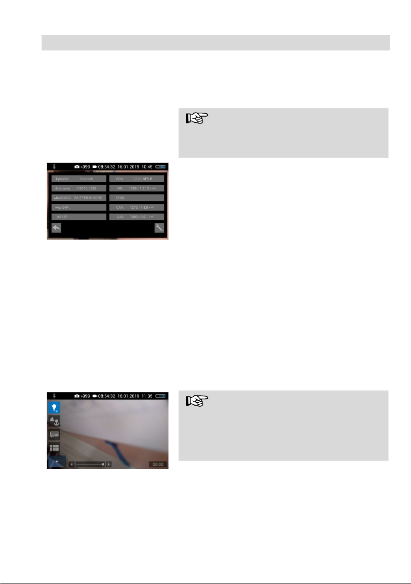
Abb. 3: Infomenü mit SOM (Firm-
ware der Kamera) und CAM (Ver-
sion des Kamerakopfes)
Die Firmware der Kamera muss Version 2.0.2
oder höher sein. Der Kamerakopf muss die Versi-
on 1.4.0 oder höher aufweisen. Die Versionen
können im Infomenü eingesehen werden, siehe
Bedienungsanleitung Wöhler VIS 700.
Arbeiten Sie mit einer älteren Kamera oder einem
älteren Kamerakopf, ist die Zusatzbeleuchtung bei
eingeschalteter Kamera dauerhaft eingeschaltet.
4.2 Einstellung der
Beleuchtung
Beim Einschalten des Kamerasystems Wöhler VIS
700 ist die Zusatzbeleuchtung immer eingeschaltet
und die Beleuchtung des Kamerakopfes auf
höchster Stufe.
Über das Helligkeitsmenü der Kamera kann die
Zusatzbeleuchtung ausgeschaltet werden. Die
LEDs des Kamerakopfes können in 3 Beleuch-
tungstufen gedimmt und anschließend ausge-
schaltet werden.
•Rufen Sie über die Menütaste der Kamera das
Kameramenü auf.
Abb. 4: Menü bei eingeschalteter
Zusatzbeleuchtung
HINWEIS!
Bei montierter Zusatzbeleuchtung erscheint für
das Helligkeitsmenü als oberster Menü-Icon eine
Glühbirne anstelle der Sonne. Bei eingeschalteter
Zusatzbeleuchtung erscheint neben der Glühbirne
ein +.
•Tippen Sie auf den Glübirne-Icon, um das
Helligkeitsmenü auszuwählen.
•Regeln Sie die Helligkeit nun gewohnt über die
Schiebeleiste oder den Joystick.

Garantie und Service
7
5 Garantie und Service
5.1 Garantie
Jede Zusatzbeleuchtung 26/40 wird im Werk in
allen Funktionen geprüft und verlässt unser Werk
erst nach einer ausführlichen Qualitätskontrolle.
Bei sachgemäßem Gebrauch beträgt die Garan-
tiezeit auf die Zusatzbeleuchtung zwölf Monate ab
Verkaufsdatum.
Die Kosten für den Transport und die Verpackung
des Geräts im Reparaturfall werden von dieser
Garantie nicht abgedeckt.
Diese Garantie erlischt, wenn Reparaturen und
Abänderungen von dritter, nicht autorisierter Stelle
an dem Gerät vorgenommen wurden.
5.2 Service
Der SERVICE wird bei uns sehr groß geschrie-
ben. Deshalb sind wir auch selbstverständlich
nach der Garantiezeit für Sie da.
•
Sie schicken die Zusatzbeleuchtung zu uns,
wir reparieren sie innerhalb weniger Tage und
schicken sie Ihnen mit unserem Paketdienst
zurück.
•
Sofortige Hilfe erhalten Sie durch unsere
Techniker am Telefon.

Konformitätserklärung
8
6 Konformitätserklärung
Der Hersteller:
WÖHLER Technik GmbH
Wöhler-Platz 1, D-33181 Bad Wünnenberg
erklärt, dass das Produkt:
Produktname: Zusatzbeleuchtung 26/40
den wesentlichen Schutzanforderungen entsprechen, die in den Richtlinien des Rates
zur Angleichung der Rechtsvorschriften der Mitgliedsstaaten über die elektromagneti-
sche Verträglichkeit (2014/53/EU) festgelegt sind.
Zur Beurteilung des Produkts hinsichtlich der elektromagnetischen Verträglichkeit wur-
den folgende Normen herangezogen:
EN
55024
EN 55022 Klasse B

Contents
9
EN
Contents
1General Information ...........................10
1.1 Operation Manual Information .....................10
1.2 Notes ...........................................................10
1.3 Intended Use ............................................... 10
1.4 Information on disposal................................ 10
1.5 Manufacturer................................................11
1.6 Important Note.............................................11
2Technical Data ....................................12
3Installing the Light Ring.....................12
4Lighting Settings ................................13
4.1 System requirements of the camera............13
4.2 Lighting Settings ..........................................13
5Warranty and Service.........................14
5.1 Warranty ......................................................14
5.2 Service......................................................... 14
6Declaration of conformity ..................15

General Information
10
1 General Information
1.1 Operation Manual In-
formation
This operation manual allows you to work safely
with the Light Ring. Please keep this manual for
your information.
The Light Ring should be employed by profes-
sionals for its intended use only.
Liability is void for any damages caused by not
following this manual.
1.2 Notes
CAUTION!
Highlights risks that can lead to damage occurring
to the device.
NOTE!
Highlights tips and other useful information.
1.3 Intended Use
The Light Ring is used for the illumination of a dark,
dusty or sooted
environment during the inspection
with the camera system Wöhler VIS
700.
The
Light Ring is used with the detachable cam-
era head Ø 26
or 40 mm. It has to be installed
between the camera head and rod
or cable. It will
be dimmed with the keys of the camera system.
1.4 Information on disposal
Electronic equipment does not belong into domes-
tic waste, but must be disposed in accordance
with the applicable statutory provisions.
You may hand in any defective batteries taken out
of the unit to our company as well as to recycling
places of public disposal systems or to selling
points of new batteries or storage batteries.

General Information
11
EN
1.5 Manufacturer
Wöhler Technik GmbH
Wöhler-Platz 1
33181 Bad Wünnenberg
Tel.: +49 2953 73-100
Fax: +49 2953 73-96100
E-Mail: info@woehler.com
1.6 Important Note
ATTENTION!
The Supplementary Light is only waterproof (IP
67) when the camera head and the rod are con-
nected. Never clean the Supplementary Light with
water, when the camera head and rod are not
connected.

Technical Data
12
2 Technical Data
Description
Data
Connection
5-pole plug connection
Light
16 white LEDs
Waterproof (only
with camera head
and rod)
IP 67
Dim
Via video inspection
system Wöhler VIS 700
Power Supply
Via video inspection
system Wöhler VIS 700
3 Installing the Light Ring
•Unscrew the camera head VIS 700 from the
camera rod VIS 700.
Fig. 5: Light Ring plugged on the
rod
•Plug the 5-pin plug of the camera rod into the
socket of the Wöhler Light Ring.
•Turn the threaded piece of the camera rod to
the right to lock it.
Fig. 6: Camera with light ring
•Plug the camera head connector into the auxil-
iary lighting connector and rotate until the
poles snap into place.
•Turn the threaded piece of the camera rod to
the right to lock it.

Lighting Settings
13
EN
4 Lighting Settings
The Light Ring can be controlled via the camera
Wöhler VIS 700.
4.1 System
requirements of
the camera
NOTE!
It is not possible to controll the Light Ring with an
older Version of the camera or the camera head.
Fig. 7: Info menu with SOM (Firm-
ware of the camera) and CAM
(Version of the camera head)
The firmware of the camera must be 2.0.2 or high-
er. The version of the camera head must bei 1.4.0
or higher. You can find the version number in the
Info menu of the camera, see manual Wöhler VIS
700.
If you work with an older camera or camera head
the the Light Ring will always be switched on when
the camera ist switched on.
4.2 Lighting Settings
When the camera system is switched on, the light
ring is switched on and the illumination of the
camera head is at the highest level.
The Light Ring can be switched off via the bright-
ness menu of the camera. The LEDs of the cam-
era head can be dimmed in 3 levels and then
switched off.
•Press the menu button of the camera to dis-
play the camera menu.
Fig. 8: Camera menu when the
light ring is switched on
NOTE!
If the light ring is installed, a light bulb will appear
as the icon for the brightness menu instead of the
sun. When the additional lighting is switched on, a
+ appears next to the light bulb.
•Tap on the bulb icon to select the brightness
menu.
•Adjust the brightness as usual using the slide
bar or the joystick.

Warranty and Service
14
5 Warranty and Service
5.1 Warranty
Each Light Ring 26/40 will be tested in all functions
and will leave our factory only after extensive qual
i-
ty control testing.
If used properly, the warranty period for the
Light
Ring
26/40 will be twelve month from the date of
sale.
This warranty does not cover the freight and pack
-
ing costs when the device is sent to the factory for
repair.
Service by non authorized personnel or making
modifications to the analyzer voids any warranty.
5.2 Service
Wöhler has built our reputation on excellence in
customer service. Therefore, of course, we are
readily available to assist you after the warranty
period ends.
•
Send us the device and we will repair it and
return it to you with our package service.
•
Immediate help is provided by our technical
staff over the telephone.

Declaration of conformity
15
EN
6 Declaration of conformity
The manufacturer:
Wöhler Technik GmbH
Wöhler-Platz 1, D-33181 Bad Wünnenberg
Declares that the product:
Light Ring
26/40
complies
with the key safety requirements set down in the guidelines of the Council for
the Harmonization of the Legal Requirements of the Member States in relation to the
electromagnetic compatibility
(2014/30/EU) and low voltage (2014/35/EU).
The following stan
dards were availed of to evaluate the product in respect of the elec-
tromagnetic compatibility:
EN 55024
EN 55022
class B

Sommaire
16
Sommaire
1Informations Générales......................17
1.1 Utilisation conforme.................................... 17
1.2 Remarques.................................................. 17
1.3 Utilisation conforme.................................... 17
1.4 Traitement des déchets............................... 17
1.5 Fabricant ..................................................... 18
1.6 Note importante........................................... 18
2Données techniques...........................19
3Montage de l’éclairage LED ...............19
4Varier l’intensité de l‘éclairage..........20
4.1 Systemvorrausetzungen der Kamera.......... 20
4.2 Varier l'intensité de l'éclairage..................... 20
5Garantie et service..............................21
5.1 Garantie ...................................................... 21
5.2 Service ........................................................ 21
6Declatation de conformité..................22

Informations Générales
17
1 Informations Générales
1.1 Utilisation
conforme
L'éclairage LED est destiné à l'illumination d'un
environne
ment sombre ou encrassé de suie pen-
dant l'inspection avec la caméra Wöhler VIS.
L'éclairage LED 26/40 s'utilise avec
la tête de
caméra détachable Wöhler Ø 26 et 40 mm . Il est
installé entre la tête de caméra et le tige ou câble
de caméra. Il est allumé et étendu avec les touches
du système de caméra Wöhler VIS
700.
1.2 Remarques
Attention !
Désigne des consignes signalant un danger dont
la non-observation peut conduire à des dom-
mages de l'appareil.
INDICATION !
Information utile
1.3 Utilisation
conforme
L'éclairage LED est destiné à l'illumination d'un
environnent sombre ou encrassé de suie pendant
l'inspection avec la caméra Wöhler VIS
700.
L'éclairage LED 26/40 s'utilise avec
la tête de
caméra détachable Wöhler Ø 26 et 40 mm
. Il est
installé entre la tête
de caméra et le tige ou câble
de caméra. Il est allumé et étendu avec les touches
du système de caméra Wöhler VIS.
1.4 Traitement des déchets
Les composants électroniques ne sont pas des
déchets domestiques. Ils doivent être éliminés en
respectant la législation en vigueur.
Les batteries défectueuses, une fois retirées de
l'appareil peuvent être déposées dans un centre
de recyclage des déchets publics, un point de
vente ou de stockage de batteries.

Informations Générales
18
1.5 Fabricant
Wöhler Technik GmbH
Wöhler-Platz 1
33181 Bad Wünnenberg
Tel.: +49 2953 73-100
Fax: +49 2953 73-96100
E-Mail: info@woehler.de
1.6 Note importante
ATTENTION!
L'éclairage LED est seulement étanche (IP 67)
avec la tête de caméra et la tige connectées.
Il ne
faut pas nettoyer l’éclairage avec de l’eau quand
la tête de caméra et la tige ne sont pas connec-
tées.

Données techniques
19
2 Données
techniques
Désignation
Valeurs
Raccord
accouplement 5 pôles
pour reccordement à la
tête et au câble/à la tige
Eclairage
18 LEDs blanches
Etanchéité (seule-
ment avec tête de
caméra et tige con-
nectées)
IP 67
varier l'intensité de
l'éclairage
Par système
d’inspection vidéo
Wöhler VIS 700
Alimentation en
électricité
Par système
d’inspection vidéo
Wöhler VIS 700
3 Montage de l’éclairage LED
•Enlevez la tête de la caméra du jonc oudu
cable de poussée en la dévissant.
Fig. 9: Éclairage LED inséré sur le
jonc de poussée de la caméra
•Insérez le connecteur à cinq pôles du jonc de
la caméra ou du câble de caméra dans la
douille de l’éclairage supplémentaire Wöhler.
•Tournez vers la droite la pièce filetée sur le
jonc de poussée pour fermer.
Fig. 10: Éclairage supplémentaire
complètement monté
•Insérez le raccordement de la tête de caméra
sur la fiche de l’éclairage supplémentaire et
tournez jusqu’à ce que les pôles encliquètent.
•Tournez vers la droite la pièce filetée sur le
jonc de poussée pour fermer.

Varier l’intensité de l‘éclairage
20
4 Varier l’intensité de l‘éclairage
L’éclairage LED peut être allumé et eteindu à par-
tir de la caméra.
4.1 Systemvorrausetz
ungen der Kamera A NOTER !
Le réglage de l’intensité de l’éclairage LED n’est
pas possible si vous travaillez avec une ancienne
version de la caméra ou une ancienne version de
la tête de caméra.
Fig. 11: Menu d’informations avec
SOM (micro logiciel de la caméra)
et CAM (version de la tête de
caméra)
Le logiciel de la caméra Wöhler VIS 700 doit être
la version 2.02 ou plus élevée. La tête de caméra
doit être de la version 1.4.0 ou plus élevée. Les
versions sont indiquées dans le menu info de la
caméra, voir manuel Wöhler VIS 700.
Si vous utilisez une caméra plus ancienne ou une
tête de caméra plus ancienne, l’éclairage supplé-
mentaire est allumé permanentement quand la
caméra est en marche.
4.2 Varier l'intensité
de l'éclairage
Quand le système de caméra est allumé,
l’Eclairage LED est allumé et l’éclairage de la tête
de caméra est au plus haut niveau.
L’éclairage LED peut être éteint à partir du menu
« luminosité » de la caméra. L’intensité des LED
de la tête de caméra peut être variée selon trois
niveaux de luminosité. Ensuite elles peuvent être
éteintes.
•Appelez le menu caméra à partir de la touche
menu
Fig. 12: Menu quand l’éclairage
LED est allumé
A NOTER !
Quand l’éclairage supplémentaire est monté, une
ampoule est affichée comme icône supérieure
dans le menu luminosité à la place du soleil. Si
l’éclairage supplémentaire est allumé, un + est
affiché à côté de l’ampoule.
•Tapez sur l’icône ampoule pour sélectionner le
menu luminosité
•Réglez la luminosité en utilisant la barre cou-
Other manuals for VIS 700
5
Table of contents
Languages:
Other Wohler Diagnostic Equipment manuals