MediSono P3V User manual


I
About this Manual
P/N: 01.54.456498
MPN: 01.54.456498011
Release Date: April, 2017
Statement
This manual will help you understand the operation and maintenance of the product better. It is
reminded that the product shall be used strictly complying with this manual. User’s operation
failing to comply with this manual may result in malfunction or accident for which the
manufacturer can not be held liable.
The manufacturer owns the copyrights of this manual. Without prior written consent of the
manufacturer, any materials contained in this manual shall not be photocopied, reproduced or
translated into other languages.
Materials protected by the copyright law, including but not limited to confidential information
such as technical information and patent information are contained in this manual, the user shall
not disclose such information to any irrelevant third party.
The user shall understand that nothing in this manual grants him, expressly or implicitly, any
right or license to use any of the intellectual properties of the manufacturer.
The manufacturer holds the rights to modify, update, and ultimately explain this manual.
Responsibility of the Manufacturer
The manufacturer only considers itself responsible for any effect on safety, reliability and
performance of the equipment if:
Assembly operations, extensions, re-adjustments, modifications or repairs are carried out by
persons authorized by the manufacturer, and
The electrical installation of the relevant room complies with national standards, and
The instrument is used in accordance with the instructions for use.

II
Terms Used in this Manual
This guide is designed to give key concepts on safety precautions.
WARNING
A WARNING label advises against certain actions or situations that could result in
personal/animals injury or death.
CAUTION
A CAUTION label advises against actions or situations that could damage equipment, produce
inaccurate data, or invalidate a procedure.
NOTE
A NOTE provides useful information regarding a function or a procedure.
The device is for veterinary use only, and the “VETERINARY USE ONLY”label is stuck to the
device. Please follow the instruction.

III
Table of Contents
Chapter 1 Introduction .................................................................................................................... 1
1.1. Features ............................................................................................................................ 1
1.2. Intended Use/Indications for Use..................................................................................... 1
1.3. Model ............................................................................................................................... 1
1.4. Contraindications ............................................................................................................. 2
1.5. General Safety Precaution Information............................................................................ 2
1.5.1. General Information................................................................................................ 2
1.5.2. Biohazard Considerations ....................................................................................... 4
1.5.3. Electrical Safety...................................................................................................... 5
1.5.4. Battery Safety.......................................................................................................... 9
1.6. Labeling Symbols .......................................................................................................... 10
Chapter 2 System Overview ......................................................................................................... 13
2.1. Appearance..................................................................................................................... 13
2.1.1. Front View............................................................................................................. 13
2.1.2. Rear View.............................................................................................................. 14
2.2. Configuration ................................................................................................................. 15
2.2.1. Standard Configuration......................................................................................... 15
2.2.2. Options.................................................................................................................. 15
Chapter 3 Transportation and Storage........................................................................................... 17
3.1. Moving the System ........................................................................................................ 17
3.2. Storage............................................................................................................................ 17
3.3. Transportation ................................................................................................................ 17
Chapter 4 Installation Instructions................................................................................................ 18
4.1. Environmental Requirements......................................................................................... 18
4.2. Unpacking Inspection..................................................................................................... 18
4.3. Connecting Procedure.................................................................................................... 18
4.3.1. Installing and Uninstalling a Cable Holder........................................................... 19
4.3.2. Installing and Uninstalling a Battery .................................................................... 20
4.3.3. Connecting and Disconnecting Probes ................................................................. 21
4.3.4. Peripheral Connections ......................................................................................... 22
4.3.5. Equipotential Bonding .......................................................................................... 24
4.3.6. Printer Installation................................................................................................. 25
4.3.7. Installing a Needle Guide...................................................................................... 26
Chapter 5 System Control............................................................................................................. 28
5.1. Powering On/Off Device................................................................................................ 28
5.2. Examining...................................................................................................................... 29
5.3. Screen Layout................................................................................................................. 30
5.4. Control Panel.................................................................................................................. 31
5.4.1. Trackball................................................................................................................ 31
5.4.2. “0~9” Numeric Keys............................................................................................. 32

IV
5.4.3. Alphabetic Keys.................................................................................................... 32
5.4.4. Function Controls.................................................................................................. 32
5.4.5. Comment Function................................................................................................ 37
5.4.6. Body Mark Function............................................................................................. 39
5.4.7. Imaging Functions................................................................................................. 41
5.4.8. Additional Control Functions................................................................................ 44
5.5. Menu .............................................................................................................................. 45
5.6. Dialog Box Operation.................................................................................................... 47
5.7. Presetting........................................................................................................................ 48
5.7.1. Entering and Exiting ............................................................................................. 48
5.7.2. Displaying / Modifying Presetting Parameters..................................................... 49
5.7.3. System Presetting.................................................................................................. 49
5.7.4. Presetting Examination ......................................................................................... 52
5.7.5. Editing Comment Library..................................................................................... 55
5.7.6. Factory Default...................................................................................................... 57
5.7.7. Presetting DICOM ................................................................................................ 57
5.7.9. Maintenance.......................................................................................................... 58
5.8. Printing........................................................................................................................... 58
Chapter 6 Operation...................................................................................................................... 60
6.1. Entering New Patient ..................................................................................................... 60
6.2. Entering or Editing Patient Information......................................................................... 60
6.3. Selecting an Examination Type...................................................................................... 60
6.4. Activating and Deactivating a Probe ............................................................................. 61
6.5. Selecting an Imaging Mode ........................................................................................... 62
6.6. Measurements and Calculations..................................................................................... 62
6.6.1. Generic Measurements in B Mode........................................................................ 63
6.6.2. Generic Measurements in M Mode....................................................................... 72
6.6.3. Generic Measurements in PW Mode .................................................................... 74
6.6.4. General Report...................................................................................................... 77
6.7. CINE Review ................................................................................................................. 78
6.8. File Management............................................................................................................ 79
6.8.1. Saving Files........................................................................................................... 79
6.8.2. File Manager ......................................................................................................... 82
6.8.3. Sending Files......................................................................................................... 84
6.9. Needle Guide Function .................................................................................................. 86
6.9.1. Enabling Needle Guide Function.......................................................................... 86
6.9.2. Calibrating Guide Line (Performing Phantom Cal).............................................. 87
6.9.3. Performing Needle Guide Function...................................................................... 88
6.9.4. Exiting Needle Guide Function............................................................................. 88
Chapter 7 Abdominal Measurements & Calculations................................................................... 89
7.1. Measurements and Calculations..................................................................................... 89
7.1.1. CBD ...................................................................................................................... 89
7.1.2. Gallbladder............................................................................................................ 90
7.1.3. Kidney................................................................................................................... 90

V
7.1.4. Bladder.................................................................................................................. 90
7.2. Abdominal Report.......................................................................................................... 90
7.3. Others............................................................................................................................. 91
Chapter 8 Obstetric Measurement and Calculation ...................................................................... 92
8.1. Obstetric Measurement and Calculation in B Mode...................................................... 92
8.2. Canine Obstetrics Measurement .................................................................................... 93
8.2.1. CRL....................................................................................................................... 93
8.2.2. GSD....................................................................................................................... 93
8.2.3. HD......................................................................................................................... 94
8.2.4. BD......................................................................................................................... 94
8.2.5. HD&BD ................................................................................................................ 94
8.3. Feline Obstetrics Measurement...................................................................................... 95
8.4. Equine Obstetrics Measurement .................................................................................... 95
8.4.1. GSD-H .................................................................................................................. 95
8.4.2. GSD-V .................................................................................................................. 96
8.5. Bovine Obstetrics Measurement.................................................................................... 96
8.6. Ovine Obstetrics Measurement...................................................................................... 97
8.7. Other Obstetrics Measurements..................................................................................... 97
8.8. Obstetric Report ............................................................................................................. 98
8.9. Others............................................................................................................................. 99
Chapter 9 Cardiology Measurement and Calculation................................................................. 100
9.1. Cardiac Measurement and Calculation in M Mode ..................................................... 100
9.1.1. LV........................................................................................................................ 104
9.1.2. Mitral Valve......................................................................................................... 106
9.1.3. Aortia................................................................................................................... 107
9.1.4. LVMW, LVMWI................................................................................................. 108
9.2. Cardiac Measurement and Calculation in B Mode...................................................... 108
9.2.1. LV........................................................................................................................ 112
9.2.2. RV (Right Ventricle Internal Diameter) .............................................................. 115
9.2.3. PA(Pulmonary Artery)........................................................................................ 115
9.3. Cardiac Measurement and Calculation in PW Mode................................................... 115
9.4. Cardiac Report ............................................................................................................. 116
9.5. Others........................................................................................................................... 117
Chapter 10 Vascular Measurements & Calculations................................................................... 118
10.1. Measurements and Calculations in PW Mode.......................................................... 118
10.1.1. Forelimb........................................................................................................... 118
10.1.2. Hindlimb .......................................................................................................... 119
10.1.3. CCA ................................................................................................................. 119
10.1.4. ICA................................................................................................................... 119
10.1.5. ECA.................................................................................................................. 120
10.1.6. Vert A ............................................................................................................... 120
10.2. Vascular Report......................................................................................................... 120
10.3. Others........................................................................................................................ 121

VI
Chapter 11 Inspection and Maintenance..................................................................................... 122
11.1.Daily Checklist............................................................................................................. 122
11.2.Cleaning and Disinfection............................................................................................ 123
11.2.1. System Surface Cleaning ................................................................................. 124
11.2.2. Probe and Probe Holder Cleaning and Disinfection ........................................ 124
11.2.3. Needle Guide Cleaning and Disinfecting......................................................... 126
11.2.4. Trackball Cleaning........................................................................................... 127
11.2.5. Replacing Fuses ............................................................................................... 127
11.2.6. Disinfectants..................................................................................................... 128
11.3.Maintenance................................................................................................................. 129
Chapter 12 Troubleshooting........................................................................................................ 130
12.1. Checkup..................................................................................................................... 130
12.2. Troubleshooting ........................................................................................................ 130
Chapter 13 Warranty and Service................................................................................................ 131
13.1. Warranty...................................................................................................................... 131
13.2. Contact information .................................................................................................... 131
Appendix I: Specifications.......................................................................................................... 132
A1.1: Electrical Safety Classifications................................................................................. 132
A1.2: Power Supply............................................................................................................. 132
A1.3: Machine Specifications.............................................................................................. 133
A1.4: Display Specifications................................................................................................ 133
A1.5: General Technical Specifications............................................................................... 133
A1.6: Probe Specifications................................................................................................... 134
A1.7: Operating, Storage and Transportation Environment................................................. 135
A1.7.1. Operating Environment:................................................................................... 135
A1.7.2. Storage and Transportation Environment:........................................................ 135
Appendix II: Ultrasound Intensity and Safety ............................................................................ 136
A2.1: Ultrasound in Medicine............................................................................................. 136
A2.2: Ultrasound Safety and the ALARA Principle ........................................................... 136
A2.3: Explanation of MI/TI ................................................................................................ 137
A2.3.1. MI (Mechanical Index) .................................................................................... 137
A2.3.2. TI (Thermal Index)........................................................................................... 137
A2.3.3. Display of MI/TI.............................................................................................. 138
A2.4: Acoustic Output ........................................................................................................ 138
A2.4.1. Factors that Contribute to Uncertainty in the Output Display ......................... 138
A2.4.2. Differences betweenActual and Displayed MI/TI........................................... 138
A2.4.3. Measurement Uncertainty................................................................................ 139
A2.5: Operator Control Features......................................................................................... 139
A2.6: Prudent Use Statement.............................................................................................. 140
A2.7: References for Acoustic Output and Safety.............................................................. 140
A2.8: Probe Acoustic Output Parameters List ..................................................................... 141
A2.8.1 :Test of Probe C361-2: ..................................................................................... 141
A2.8.2 : Test of Probe C611-2: .................................................................................... 145

VII
A2.8.3: Test of Probe L761-2:....................................................................................... 149
A2.8.4: Test of Probe L743-2:....................................................................................... 153
A2.8.5: Test of Probe V563-2: ...................................................................................... 157
A2.8.6: Test of Probe C321-2: ...................................................................................... 161
Appendix III: MeasurementAccuracy........................................................................................ 166
Appendix IV: EMC Information-Guidance and Manufacture’s Declaration .............................. 167
Appendix V: Order List............................................................................................................... 171
Appendix VI: Glossary ............................................................................................................... 172

P3V Veterinary Digital Ultrasonic Diagnostic Imaging System User Manual
- 1 -
Chapter 1 Introduction
1.1.Features
The P3V is a portable Veterinary Diagnostic Ultrasound System, which applies advanced
technologies such as Phased Inversion Harmonic Compound Imaging (eHCI),
Double-Beam-Forming (D Beam), Speckle Resistance Imaging (eSRI), Synthetic Receiving Aperture
(SRA)and Spatial Compounding Imaging, etc. Various image parameter adjustments, 12.1
inch LCD and diverse probes are configured to provide clear and stable images.
Display modes:
B, 2B, 4B, B+M, M, and PW.
File management:
It supports local disk and removable disk storage. USB interface enables fast image uploading to
your computer in the real-time mode. It has a 504 MB storage capacity.
Operation:
The folding keyboard designed with trackball is easy and convenient for various types of
operation.
Generic Measurements and Calculations:
B Mode: Distance, Cir/Area (Ellipse/Trace), Volume, Ratio, % Stenosis, Angle, and Histogram.
M Mode: Distance, Time, Slope and Hear Rate.
PW Mode: Velocity, Heart Rate, Time, Acceleration, Resistance Index (RI), Auto (auto trace.
1.2.Intended Use/Indications for Use
The veterinary diagnostic ultrasound system (P3V) is applicable for animal ultrasound evaluation
in pet hospitals, veterinary clinics, animal farms, zoos, horse racing centers, and animal
cultivation/breeding bases. It is intended for use by or on the order of a veterinarian or similarly
qualified health care professional, in abdomen, obstetrics, muscle, tendon, cardiology, and
vascular exams.
1.3.Model
P3V

P3V Veterinary Digital Ultrasonic Diagnostic Imaging System User Manual
- 2 -
1.4. Contraindications
The equipment is not applicable to the diagnosis of the pneumatic organs that contain gas
such as lung, stomach, intestines, etc.
It is recommended not to examine the parts with wounds or acute inflammation to avoid
cross infection.
The equipment is not intended for ophthalmic use or any use causing the acoustic beam to
pass the eye.
1.5. General Safety Precaution Information
1.5.1. General Information
CAUTION
1. Federal (U.S.) law restricts this device to sale by or on the order of a veterinarian.
2. The pictures and interfaces in this manual are for reference only.
NOTE: This equipment is not intended for home use.
The reliability of the device and the safety of operators and patients are considered during
product design and production. The following safety and preventive measures should be carried
out:
WARNING
1. This equipment is not intended for treatment.
2. The diagnosis and examination function of the ultrasonic imaging management
system should be integrated with clinical situation of animals, and the diagnostic
results are only for veterinarian’s reference.
3. The device should be operated by qualified operators or under their instructions.
4. The device should be operated appropriately to avoid mechanical damage to the
transducer.
5. Do not alter parameters of the device at will. If it is necessary, please consult the
manufacturer or authorized representatives for service.
6. The device has already been adjusted to its optimum performance. Do not adjust any
presetting control or switch, unless it is listed in this manual.
7. If the device breaks down, please shut down the machine immediately and contact
the manufacturer or authorized representatives.

P3V Veterinary Digital Ultrasonic Diagnostic Imaging System User Manual
- 3 -
8. Only accessories supplied or recommended by the manufacturer can be used, the
battery and probes of the manufacturer can be only used on the manufacturer’s
systems. Otherwise, the performance and electric shock protection can not be
guaranteed. If electrical or mechanical equipment from other companies need to be
connected to the device, please contact the manufacturer or authorized
representatives before connection.
9. EXPLOSION HAZARD-Equipment is not suitable for use in the presence of a
flammable anesthetic mixture with air or with oxygen or nitrous oxide.
10. If the liquid crystal material leaks from the panel, it should be kept away from the eye
or mouth. In case of contact with hands, skin or clothes, it has to be washed away
thoroughly with soap.
11. Do not use in a wet environment or when the relative humidity exceeds 80%.
12. Use protective barriers (gloves and transducer sheaths) whenever possible. Follow
sterile procedures when appropriate. Thoroughly clean Transducers and reusable
accessories after each patient examination and disinfect or sterilize as needed. Refer
to transducer use and care instructions. Follow all infection control policies
established by your office, department or institution as they apply to personnel and
equipment.
13. Not intended for Ophthalmic use.
14. If a sterile transducer cover becomes compromised during an intra-operative
application involving a patient with transmissible spongiform encephalopathy, such
as Creutzfeldt-Jakob disease, follow the guidelines of the U.S. Disease Control
Center and this document from the World Health Organization:
WHO/CDS/APH/2000/3, WHO Infection Control Guidelines for Transmissible
Spongiform Encephalopathies. The transducers for your system cannot be
decontaminated using a heat process.
15. Contact with natural rubber latex may lead to a severe anaphylactic reaction in
persons sensitive to the natural latex protein, Sensitive users and patients must
avoid contact with these items. The manufacturer strongly recommends that
health-care professionals identify their latex-sensitive patients, and refer to the March
29, 1991 Medical Alert on Latex products. Be prepared to treat allergic reactions
immediately.
16. This device is not suitable for intra-cardiac use or direct cardiac contact.
17. The system shall not be serviced or maintained while in use with a patient.
18. Install the system according the EMC guidance provided in Appendix IV.

P3V Veterinary Digital Ultrasonic Diagnostic Imaging System User Manual
- 4 -
19. The use of transducer and connecting cable not supplied by the manufacturer may
result in increased emissions or decreased immunity of the equipment.
20. No modification of this equipment is allowed.
21. The system should be maintained regularly, at least annually, by a qualified
technician who has adequate training, knowledge and experience. That person
should be familiar with the Service Manual, available from representative of the
manufacturer.
22. The appliance coupler or mains plug is used as isolation means from supply mains.
Position the system in a location where the operator can easily access the
disconnection device.
23. Do not use a battery that leaks, emits an odor, appears deformed, or discolored.
Immediately replace it with a new manufacturer -supplied battery and dispose of the
old battery according to local regulations. Replace a battery that has reached the end
of its service life.
1.5.2. Biohazard Considerations
WARNING
1. This device is not suitable for intracardiac use or direct cardiac contact.
2. The manufacturer makes every effort to manufacture safe and effective probes. You
must take all necessary precautions to eliminate the possibility of exposing patients,
operators, or third parties to hazardous or infectious materials. These precautions
should be considered in the use of any application that may indicate the need for
such care, and during endocavity scanning.
Ultrasound may be harmful to human body. This device should be used for valid reasons,
for the shortest period of time, and at the lowest mechanical and thermal indices necessary to
produce clinically acceptable images. According to the ALARA (As Low As Reasonably
Achievable) principles, acoustic output should be set to the lowest level required to satisfactorily
perform the examination. Long time exposure should be avoided. For the parameters of sound
output, please refer to appendix II.
The P3V complies with the requirements of applicable International Electrotechnical
Commission (IEC) standards in terms of safety and acoustic output levels.

P3V Veterinary Digital Ultrasonic Diagnostic Imaging System User Manual
- 5 -
1.5.3.Electrical Safety
WARNING
1. If you have any questions about the grounding connection, use the battery but not the
AC power supply.
2. To ensure grounding reliability, only connect the system to a hospital-grade power
receptacle.
3. The AC power connector plug for the ultrasound system is a three-prong grounded
plug and should never be adapted to any two-prong (non-grounded) outlet, either by
modifying the plug or by using an adapter.
4. To avoid electrical shock, never modify the ultrasound system’s AC power circuits. To
ensure grounding reliability, connect the system only to an equivalent outlet.
5. SHOCK HAZARD-Do not attempt to connect or disconnect a power cord with wet
hands. Make certain that your hands are clean and dry before touching a power cord.
6. No user serviceable parts are inside the system. All repairs on the system must be
performed by the manufacturer certified service personnel.
7. The equipment should be installed by a qualified service engineer. Do not try to
access the interior of the main unit. Only authorized service personnel could remove
the unit cover.
8. Before use, you must make sure that there is no visible evidence of damage on the
equipment, cables and probes, which may affect patient safety or diagnostic capability.
The recommended inspection interval is once per week or less. If damage is evident,
replacement is recommended before use.
9. Equipment connected to the P3V and located in the patient vicinity must be powered
from a medically-isolated power source or must be a medically-isolated device.
Equipment powered from a non-isolated source can cause your system to exceed
leakage current limits. Enclosure leakage current created by an accessory or device
connected to a non-isolated outlet may add to the enclosure leakage current of the
imaging system.
10. Use an extension cord or multi-socket outlet setup to provide power to the ultrasound
system or to the system’s peripheral devices, may compromise the system grounding
and cause your system to exceed leakage current limits.
11. To avoid electrical shock and damage to the system, turn off and disconnect the
device from the AC power source before cleaning and disinfecting.
12. When more than one medical device is connected to the patient, leakage current of
the devices is summed together. Take caution.
13. Don’t touch the signal input or output connector and the patient simultaneously.

P3V Veterinary Digital Ultrasonic Diagnostic Imaging System User Manual
- 6 -
14. Periodically have the integrity of the system ground checked by a qualified service
engineer.
15. To avoid the possibility of electrostatic shock and damage to the system, avoid using
aerosol spray cleansers on the monitor screens.
16. Do not touch the connector pins on the transducer port.
17. Parts and accessories used must meet the requirements of the applicable
IEC/EN60601 series safety standards, and/or the system configuration must meet the
requirements of the IEC/EN60601-1.
18. Do not touch accessible parts of non-medical electrical equipment and the patient
simultaneously.
19. Any non-medical equipment (such as the external printer) is not allowed to be used
within the patient vicinity (1.5m/6ft.)
20. Use an extension cord or multi-socket outlet setup to provide power to the ultrasound
system or to the system’s peripheral devices, may compromise the system grounding
and cause the system to exceed leakage current limits.
21. It is not suggested to use a multiple socket-outlet with the device, if have to, make
sure that the multi-socket complies with the requirement specified in Chapter 16 of
IEC 60601-1:2005, or the multi-socket is with an isolation transformer. And the
multi-socket shall not be placed on the floor.
22. SHOCK HAZARD - Don't connect electrical equipment, which has not been supplied
as a part of the system, to the multiple portable socket-outlet supplying the system.
23. SHOCK HAZARD - Don't connect electrical equipment, which has been supplied as a
part of the system, directly to the wall outlet when the non-medical equipment is
intended to be supplied by a multiple portable socket-outlet with an isolation
transformer.
CAUTION
1. Do not spray cleansers on the system, as this may force cleaning fluid into the
system and damage electronic components. It is also possible for the solvent fumes
to build up and form flammable gases or damage internal components.
2. Do not use any fluid onto the system surface, as fluid seepage into the electrical
circuitry may cause excessive leakage current or system failure.
3. To ensure proper grounding and leakage current levels, it is the policy of the
manufacturer to have an authorized representative or an approved third party to
perform all on-board connections of documentation and storage devices to the P3V.
4. The device and accessories are to be disposed of according to local regulations
after their useful lives. Alternatively, they can be returned to the dealer or the

P3V Veterinary Digital Ultrasonic Diagnostic Imaging System User Manual
- 7 -
manufacturer for recycling or proper disposal. Batteries are hazardous waste. Do
not dispose them together with house-hold garbage. At the end of their life hand the
batteries over to the applicable collection points for the recycling of waste batteries.
For more detailed information about recycling of this product or battery, please
contact your local Civic Office, or the shop where you purchased the product.
5. Please use the standard power cord as the input line of the network power supply for
the adapter to reduce risk.
6. Excessive dust and dirt could clog internal airflow and cause overheating. Do not
use in a dusty environment.
7. Do not use in locations subject to vibration.
8. The system generates radio frequency energy, which may cause interference with
other devices in the vicinity. If interference is suspected, try re-orienting or relocating
the equipment.
9. The use of electrosurgical units or other devices that generate radio frequency
interference may cause image distortion or other malfunction.
10. Verify measurement results prior to entering them into a report.
11. Contact your local distributor or service of the manufacturer if there is excessive
noise from the system speaker or fans.
12. Please read and understand cleaning instructions prior to use.
13. Please read and understand maintenance instructions prior to use.
14. Please read and understand instructions for system operation prior to use.
15. Ensure that the system vents are clear and unobstructed.
16. Confirm patient identification information prior to storing or printing any exam
information.
17. If you have any questions about maintenance, technical specifications, or system
functionality, please contact your local distributor or service of the manufacturer.
18. Ultrasound images occasionally have artifacts, and should only be used as one part
of an overall clinical assessment.
19. To avoid electrical shock, turn off and disconnect the device from the AC power
source before cleaning and disinfecting.

P3V Veterinary Digital Ultrasonic Diagnostic Imaging System User Manual
- 8 -
NOTE:
The probe stops transmission after freezing, disconnecting, falling off, or entering
sleeping mode. Main control software checks the probe connection all the time, once
probe disconnects from the probe socket, the system stops transmission.
Electromagnetic Compatibility (EMC)
Operating the P3V in close proximity to sources of strong electromagnetic fields, such as
radio transmitter stations or similar installations may lead to interference visible on the
monitor screen. However, the device has been designed and tested to withstand such
interference and will not be permanently damaged.
EMI Limitations
Ultrasound machines are susceptible to Electromagnetic Interference (EMI) from radio
frequencies, magnetic fields, and transients in the air of wiring. Ultrasound machines also
generate EMI. The P3V complies with limits as stated on the EMC label. However, there is no
guarantee that interference will not occur in a particular installation.
Possible EMI sources should be identified before the unit is installed.
Electrical and electronic equipment may produce EMI unintentionally due to one of the following
defects:
➢High frequency electrotome
➢Transformer
➢Defibrillator
➢Wireless LAN equipment
➢Medical lasers
➢Scanners
➢Cauterizing guns
➢Computers
➢Monitors
➢Fans
➢Gel warmers
➢Microwave ovens
➢Light dimmers
➢Portable phones
The presence of a broadcast station or broadcast van may also cause interference.
If you find strong interference shows on the screen, please check the sources.

P3V Veterinary Digital Ultrasonic Diagnostic Imaging System User Manual
- 9 -
1.5.4. Battery Safety
To prevent the battery from igniting, emitting fumes, bursting, injuring personal, damaging
equipment, pay attention to the following precautions.
WARNING
1. Do not expose the battery to temperatures above 60 °C, or leave the battery in
strong and direct sunlight.
2. Do not charge the battery near heat sources, such as a fire, heater, or direct
sunlight.
3. If the battery leaks or emits an odor, remove it from all possible flammable sources.
4. The battery has a safety device. Do not disassemble or alter the battery.
5. Do not heat the battery or discard it in fire.
6. Do not solder the battery.
7. The polarities of the battery terminals are marked near the connector, do not
connect or storage them with a metal material.
8. Do not connect the battery to the electrical power outlet.
9. Keep the battery away from fire and other heat sources.
10. Do not use a damaged battery.
11. Do not put the battery into a microwave oven or pressurized containers.
12. If the battery emits heat or an odor, is deformed, or in any way appears abnormal
during use, recharging or storage, immediately remove it and stop using it. If you
have any questions about the battery, consult the manufacturer or your local
representatives.
13. If the show date/time of the system is incorrect, or the show date/time needed to be
reset every time after powering the system, please replace the battery. If the battery
still can not work normally, contact the manufacturer for service.
14. Only use an manufacturer supplied battery. Read and understand the battery
installation instructions prior to changing the battery.
CAUTION
1. Do not force the battery into the system.
2. Do not immerse the battery into water or allow it get wet.
3. Please recharge the battery every month if the battery is to remain idle for a long

P3V Veterinary Digital Ultrasonic Diagnostic Imaging System User Manual
- 10 -
time.
4. Do not pierce the battery with sharp objects, or hit it.
5. Charge the battery between 0 °C and 40 °C and store it between -20 °C and 60 °C,
which affects battery life.
6. Only use the battery and charge the battery with the manufacturer’s equipment, and
charge the battery with the system.
7. To avoid the possibility of electrostatic shock and damage to the battery, avoid using
the battery near the place where may cause static.
8. Prevent the battery from children.
9. Do not touch the battery’s leaks that may make you uncomfortable. If the leaks go
into eyes, do not knead eyes, but wash with clean water and send to hospital
immediately.
10. Only use the battery with the P3V system.
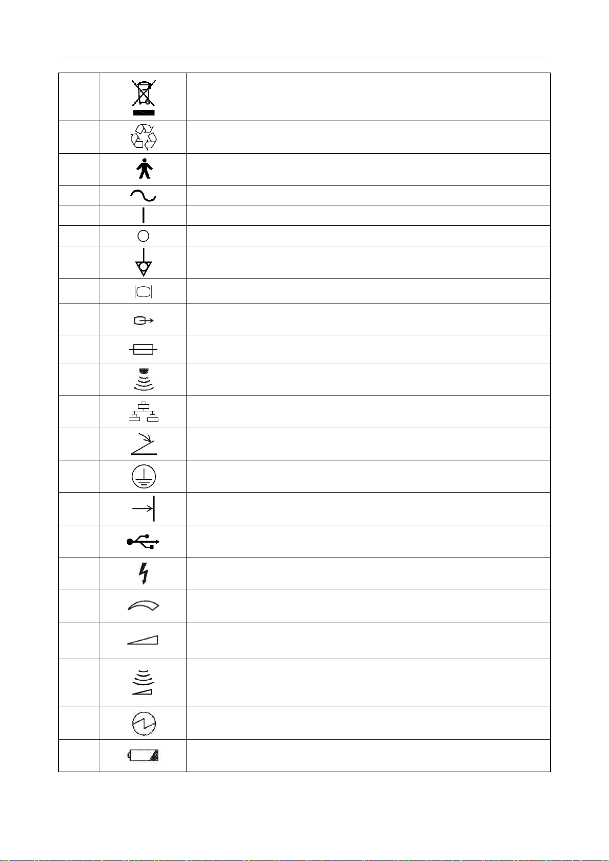
1.6. Labeling Symbols
Descriptions of symbols of the device are shown in table 1-1.
No.
Symbol
Definition
1
Serial Number
2
P/N
Part Number
3
Date of Manufacture
4
Manufacturer
5
Operating instructions
6
Warning
(Background: Yellow; Symbol & outline: Black)
7
Refer to User Manual
(Background: Blue; Symbol: White)
8
Caution
9
Biological Risks
P3V Veterinary Digital Ultrasonic Diagnostic Imaging System User Manual
- 11 -
10
Disposal method. It indicates that the equipment should be sent to special
agencies according to local regulations for separate collection after its
useful life.
11
General Symbol for Recovery / Recyclable
12
Type B Applied Part
13
Alternating Current (a.c.)
14
ON (AC power supply)
15
OFF (AC power supply)
16
Equipotentiality
17
VGA output, External Monitor
18
S-Video/ Video output port
19
Fuse
20
Probe socket
21
Computer network
22
Foots witch
To identify a footswitch or the connection for a footswitch.
23
Protective earth (ground)
24
Recording on an information carrier
25
USB (Universal Serial Bus) Connection
26
Dangerous voltage
27
Variability, for rotating movement
Rotate clockwise to increase the value, and counterclockwise to decrease.
28
Variability
Adjust right to increase the value, and left to decrease.
29
Variation of ultrasound energy
To adjust acoustic power(reserved)
30
Electric energy
31
Battery check

P3V Veterinary Digital Ultrasonic Diagnostic Imaging System User Manual
- 12 -
32
IPX7
Degree of protection provided by enclosures (IP Code): temporary
immersion. For the probe but not including the probe connector.
33
/
Power off/on the system
34
Brightness
35
Contrast
36
Sound muting
37
Loudspeaker
To adjust volume in PW mode
NOTE: The user manual is printed in black and white.
Table 1-1 Descriptions of Symbols
Table of contents
Other MediSono Diagnostic Equipment manuals


