Rice Lake CLS-M iQube2 User manual

iQUBE2® Junction Box
Quick-Start Guide
Use this document to install the iQUBE2using Rice Lake Weighing Systems recommended settings. It is written
for an 8-cell truck scale that is being used with two iQUBE2CPU boards.
Load cells or simulators must be connected before using the instructions in this document. See the iQube2
installation manual (available on the Rice Lake website at www.ricelake.com).
RS-422 and RS-485 are used interchangeably. TEDS is not supported.
Configuration using 920i
Establish a Connection
1. Connect the iQUBE2and the 920i®using an RS-422 connection.
RS-422 is recommended due to the 115,200 baud rate and a maximum distance of 1000' at this high baud
rate. RS-232 has a maximum distance of 10'.
Table 1 indicates the connections for RS-422 communications between a 920i and the iQUBE2.
Two-wire half duplex is available on Port 4 of the 920i.
2. Set S2 dip switches on CPU board to 485 (both set to OFF). See Figure 10 on page 6 for S2 dip switch
locations.
If a change is made to switch position, cycle power on the iQUBE2while in Setup mode, switch position is
read on power-up.
3. Once power is on again, place SW1 in the OFF position.
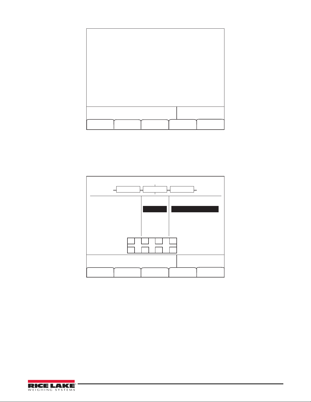
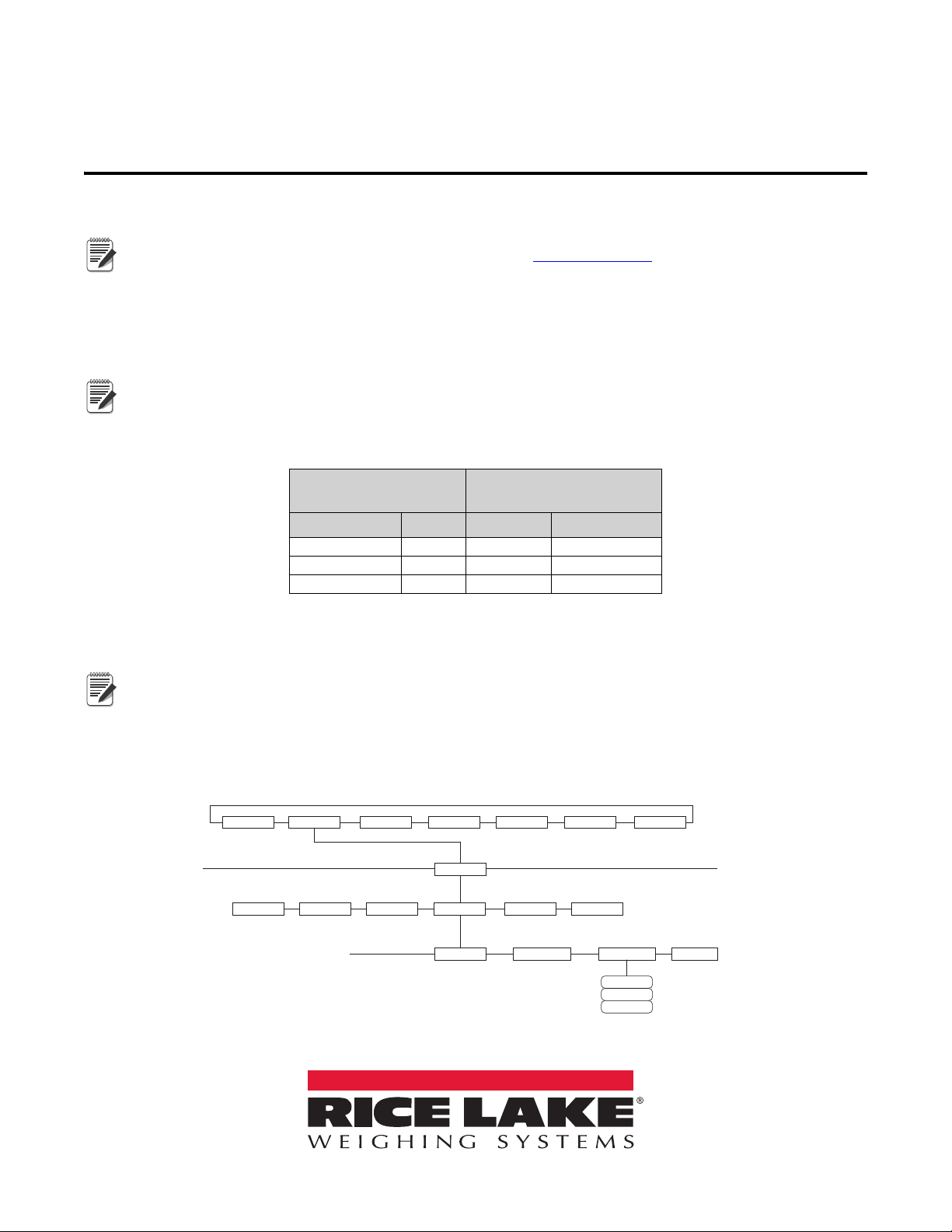
4. Enter Config mode on the 920i and navigate to the PORTTYPE under the SERIAL menu.
5. Change the PORTTYPE parameter to 422.
Figure 1. PORTTYPE Parameter
920i Board
J10 Connector (Port 4)
iQUBE2
J7 Connector
RS-422 Signal Pin Pin RS-422 Signal
GND 1 1 GND1
RS-422 A 5 4 RS-485 A
RS-422 B 6 5 RS-485 B
Table 1. RS-422 – 2-Wire Connections to 920i
Note
Note
Note
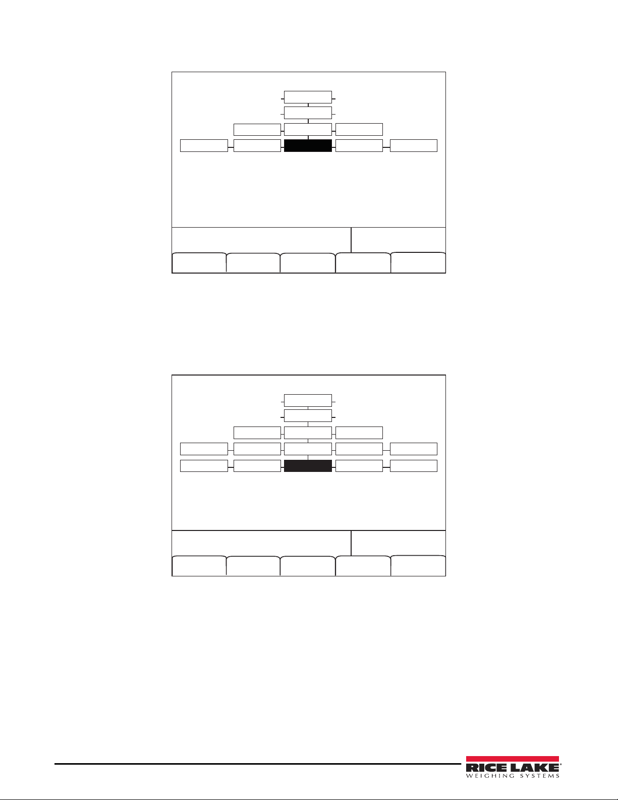
SCALES SERIAL FEATURE PFORMT SETPTS DIG I/O VERS
PORT 4
CONFIG
PROGIN CMD
…
SCALE IQUBE2IND SC DISPLAY
COMM SEL PORTTYPE UPDATE
232
422
485
PN 119611 Rev A
February 07, 2017

2iQUBE2 Quick-Start Guide
6. Navigate to the CONFIG menu and press the Connect softkey (see Figure 2).
Figure 2. CONFIG Menu
7. The serial number displays (i.e., 123XX456 *NONE* *NONE* NONE*)
If the serial number does not display, check wiring and dip switches.
Add a Secondary Board to the System
1. Under CONFIG, navigate to the BOARDS parameter and select the Auto Assign softkey. Green lights on the
CPU board start blinking on all cells.
Figure 3. BOARDS Parameter
2. Press and release the SETUP (S1) button on secondary board #1. Cells 5-8 are now available to the system
and registers its serial number with the primary board. The lights on the board will stop blinking.
3. Press the SETUP (S1) button on the primary board when the secondary unit has been assigned.
4. The primary board serial number and any assigned secondary board serial numbers will display.
12/20/2010 01:57PM
Connect
CONFIG COMM SEL
UPDATE
iQube2 Configuration
Default Save
and Exit
Upload Download
IQUBE2
PORT4
SERIAL
PROGIN
DISPLAY
PORTTYPE
PORTTYPE
12/20/2010 01:57PM
CONFIG COMM SEL
UPDATE
iQube Boards
Number of iQube2 boards on port
Save
and Exit
Auto Assign Manual
Assign
IQUBE2
PORT4
SERIAL
PROGIN
DISPLAY
PORTTYPE
PORTTYPE
BOARDS CELLS
COMM SCALES
DIGIO

3
Figure 4. Primary and Secondary Boards screen
5. Press the Done softkey.
Configure and Add Load Cells
1. Under CELLS, set the capacity and m/v.
2. Add cells 5-8 to Scale 1 under the SCALES » SERIAL menu.
Figure 5. Cells 5-8 added to Scale 1
3. Download to the iQUBE2.
12/20/2010 01:57PM
Auto Assign Edit
Primary
0 123XX456
Secondary
1) 65 456XX789
2) __ _________
3) __ _________
Done
12/20/2010 01:57PM
Remove
SCALES
AVAILABLE Cells ASSOCIATED CellsSCALES
CELL#1
CELL#2
CELL#3
CELL#4
CELL#5
CELL#6
Scale 1
Scale 2
Scale 3
Scale 4
Scale 5
CELLS SMPRAT
A1 A3 B1 B3
A2 A4 B2 B4

4iQUBE2 Quick-Start Guide
Add iQUBE2to the 920i
1. From the SCALES menu, drop down to CONFIG.
2. Press the Change Type softkey until Available iQubes displays.
Figure 6. Scale Association screen
3. Select Port 4 - Scale 1 and press the ADD softkey to add it to Associated iQUBES.
4. Press the Save and Exit softkey.
5. Continue with calibration using the installation manual.
Configuration using iRev
1. Complete Steps 1 - 4 on page 1.
2. From the iRev4 File menu, select New.
Configure Communications
1. From the System Parameters section, press Communications.
2. Click on Port 4.
3. In the General tab, set the input type to iQube2 and the Port
type to RS-485.
Configure and Add Load Cells and Secondary Board
1. Select the iQUBE2tab.
Figure 7. Serial port iQUBE2 settings
2. Press Load Cell Configuration and update as needed.
12/20/2010 01:57PM
Connect
Default Save
and Exit
Upload Download
CONFIG
SCALES
AVAILABLE IQUBES ASSOCIATED IQUBESSCALES
Port 4 - Scale 1 Scale 1
Scale 2
Scale 3
Scale 4
Scale 5

5
3. Press Secondary Board Communications.
4. In the Secondary Board One ID text box, enter the serial number found on the secondary board (see
Figure 10 on page 6).
5. In the Address text box, enter a number higher than one. Starting secondary board address numbering at 65
is recommended.
Figure 8. Secondary Board Communications
6. Press Configure Load Cell Assignments and move desired cells to the right.
Figure 9. Load cell assignments
7. Press Scale Property Configuration and update as needed.
Configure Scale #1
1. From the System Parameters section, click Scales. See Figure 1.
2. Double-click Scale #1.
3. Under Source Types, select iQube2 Systems and associate Port 4.
Save and Download Configuration to iQUBE2
1. From the File menu, select Save As to save the file. Name it appropriately.
2. From the Communications menu, select Connect.
3. Download all configuration steps. Mark the Download to iQube2 checkbox.
4. On the 920i, press the Save and Exit softkey. A weight displays.
5. Continue with calibration using installation manual.

230 W. Coleman St. • Rice Lake, WI 54868 • USA
U.S. 800-472-6703 • Canada/Mexico 800-321-6703 • International 715-234-9171 • Europe +31 (0)26 472 1319
Rice Lake Weighing Systems is an ISO 9001 registered company.
© Rice Lake Weighing Systems Specifications subject to change without notice.
www.ricelake.com
Figure 10. iQUBE2CPU Board Wiring
DO NOT connect sense to TD+ or TD-. These terminals are for TEDS communication only
PN 119611 Rev A
February 07, 2017
Other manuals for CLS-M iQube2
2
Table of contents
Other Rice Lake Diagnostic Equipment manuals