Meditech ABPM-05 User manual

SERVICE MANUAL
MEDITECH ABPM-05
All manuals and user guides at all-guides.com
all-guides.com
Operation of the Meditech ABPM-05 device BP5I2241 – 2006.05.25.
Operation of Meditech ABPM-05
The device' intended u e i to equentally mea ure blood pre ure and tore the re ult
over a period of 24 hour , during the normal daily activity of the patient.
ABPM-05 i a battery operated electronic device with a power ource of 2 AA ized batterie
or a NiMH accumulator.
The input of the DC-DC tran former with IC13 witch mode i connected to the power
ource via F2 fu e. It provide a VSTAB voltage of approximately 5V which upplie the IC8
upervi or microcontroller, the LCD1 LCD driver and the two analogou witche IC: IC9 and
IC15. The ame voltage charge the button cell B1 through D2 diode and R12 re i tance.
When there i no operating power ource in the device, the B1 button cell upplie the IC
power need (VORA) of IC6 clock.
The digital part of the mea urement electronic operate from the VKAP voltage, which i the
ame a the VSTAB voltage, but it can be witched off by the IC8 upervi or microcontroller
through OFF ign to the T3 tran i tor. The electronic of pre ure mea urement operate
through VANA power upply, which i created from a VKAP ign by the IC16 fix 4V
tabili ator.
High current con umption component (motor pump and valve ) operate from the VPOWER
voltage. Thi voltage i produced by the IC14 DC-DC tran former and it i u ually 3.6 V, but
the IC1 main microcontroller can increa e it up to 4.6 V via a GEAR ign. The DC-DC
tran former i connected to the power ource via the F1 fu e. It operate only, if the main
microcontroller i witched on via VPEN ign and only if the upervi or microcontroller allow
it through a VPWR ign. In ca e of witching it off, the operation of the motor and the valve
i attached via the T2 FET a well. Thi dual cut off i a afety function, o that it will al o
happen in ca e of any component failure.
The upply (VRXD) of the T4,T5 tran i tor i normally between 4.5 and 5 V. There i an off
mode of the device, when it' „totally” witched off. In thi ca e the upervi or
microcontroller IC8 witche even thi upply off in order to decrea e the current
con umption.
In the stand-by mode of the device, the upervi or microcontroller IC8 regularly read the
tatu of the two pu hbutton of the device, the TIMER interrupt line of the real-time clock
IC6, and the pre ence of any ignal on the optical erial line. If either pu hbutton i pre ed,
or the real-time clock IC6 end a TIMER ignal, or a character i received on the optical
erial line, the upervi or microcontroller IC8 witche the other part of the device on
(VKAP, VANA). Now the device i in on mode.
Then, in thi on mode of the device, the upervi or microcontroller IC8 ha mainly afety
function .
In it on mode, the ABPM-05 device i controlled by the main microcontroller IC1. The main
microcontroller execute the program tored in the IC3 EPROM, and it u e the IC4 external
RAM during runtime, too. It read the current time from the IC6 real-time clock and it et
the real-time clock to end a TIMER ignal after 1 minute. It communicate with the IC6
real-time clock and the IC7 LCD driver through the SCL and SDA of the I2C bu .
The mea urement plan (monitoring chedule) and the re ult (blood pre ure and pul e rate
reading , event marker , ervice and error code ) are tored in the IC5 EEPROM. The main
microcontroller can read and write the EEPROM u ing a imulated I2C bu , but writing ha
to be enabled on the DWP line handled by the upervi or microcontroller IC8, too. Thi can
be accompli hed by ending a command to the upervi or microcontroller.
The main microcontroller IC1 can communicate with the u er’ per onal computer on an
optical erial line. Communication i initiated by the u er’ per onal computer in each ca e.
The ignal ent by the per onal computer through one fiber of a twin pla tic optical cable
are received by the photodiode of the optical connector D3, they reach the receiver ba ed
Meditech page 1 of 2 page
All manuals and user guides at all-guides.com

Operation of the Meditech ABPM-05 device BP5I2241 – 2006.05.25.
on the tran i tor T4 and T5, then the ignal conditioner IC10A. The conditioned
a ynchronou erial ignal are then received and interpreted by the main microcontroller.
The a ynchronou erial ignal ent by the main microcontroller IC1 go through the ignal
conditioner IC10B to the LED of the optical connector D3, driven by the tran i tor T6. Optical
ignal ent by the device u e the other fiber of the twin pla tic optical cable to be
tran ferred to the u er’ per onal computer.
The pneumatic y tem of the ABPM-05 device con i t of the motor pump MOT1, the
operating valve V1, the afety valve V2, the pre ure en or IC17, the blood pre ure
mea urement cuff, and the airway connecting component . Du t protection of the pneumatic
y tem i en ured by du t eparation filter , one on the uction ide of the motor pump
MOT1, another in the tube going to the cuff connector.
The piezo-re i tive pre ure en or bridge IC17 convert pre ure level in the pneumatic
y tem to electric ignal. The bridge i upplied by a current generator con i ting of the
active component IC11B, T7-T9. The output ignal of the pre ure en or bridge i going
through an amplifier-filter tage ba ed on the operating amplifier IC12, IC11A and IC11D to
the internal AD converter of the main microcontroller IC1. The bridge balance at zero
pre ure level i et by the choice of appropriate value re i tor for po ition R32 and R33,
while the amplification by the choice of an appropriate value re i tor for po ition R41.
For the increa ed accuracy of pre ure mea urement, the o cillation ignal are amplified the
AC-coupled tage ba ed on the IC11C operating amplifier, then they are converted by the
internal AD converter of the main microcontroller IC1.
The upervi or microcontroller IC8 open and clo e the afety valve V2 due to the
command received from the main microcontroller IC1. For afety rea on , however, it
keep the afety valve clo ed for maximum approximately 3 minute . If it doe not receive a
command from the main microcontroller to open the afety valve within thi timeout, it
open the afety valve and re et the main microcontroller.
The operating valve V1 i controlled by the main microcontroller IC1. The valve will be
opened if there are ome maller pre ure tripping (low pre ure) during the
mea urement .
The motor pump MOT1 i controlled by the main microcontroller a well. In order to be more
ilent, the motor u ually operate on a lower voltage. In ca e of a higher pre ure, the main
microcontroller increa e the voltage of the motor through a GEAR ign.
The buzzer BZ1 (which give an acou tic acknowledgement if a pu hbutton of the device i
pre ed) and the jumper JP1 (which erve only calibration purpo e ) are connected to the
main microcontroller IC1.
At the appropriate command, the main microcontroller IC1 mea ure the voltage of the
operating power ource through the re i tor network con i ting of the re i tor R76 and
R75, and it write the re ult to the LCD, thu making it po ible for the u er to check the
remnant power of the AA ize batterie .
The IC13 DC-DC tran former check the inlet voltage through the R66, R67 re i tance
divider. If the value fall under the afe rate, the upervi or microcontroller IC8 witche the
main microcontroller IC1 off, attache the operation of the motor and the opene the clo ed
valve . The main microcontroller will be kept witched off a long a the power upply i too
low and it' operation will be only allowed if the power upply i back to the normal level.
Meditech page 2 of 2 page
All manuals and user guides at all-guides.com

ABPM-05 SERVICE INSTRUCTIONS BP5I4221 – 2006.05.12.
ABPM-05 SERVICE INSTRUCTIONS
Tools:
- Adjustab e, current imited power supp y (0.5-3V, 3A)
- Digita mu timeter (min. 3 digits, 0.1-10V, 1mA-2A)
- So dering iron, screw-driver, pincers
- Pressure meter (0-300 mmHg, ±1 mmHg)
- Pump, va ve and tubing
- PC and OI3 (or OI4) optica interface
- User program: CARDIOVISION v1.7 or ater
- Service program: ABPM Service v1.0.0.26 or ater
Chapters:
- SERVICE PROCEDURE
- CHECK PROCEDURES
- REPAIR METHODS
- TYPICAL PROBLEMS
Meditech page 1 of 10 pages
All manuals and user guides at all-guides.com
ABPM-05 SERVICE INSTRUCTIONS BP5I4221 – 2006.05.12.
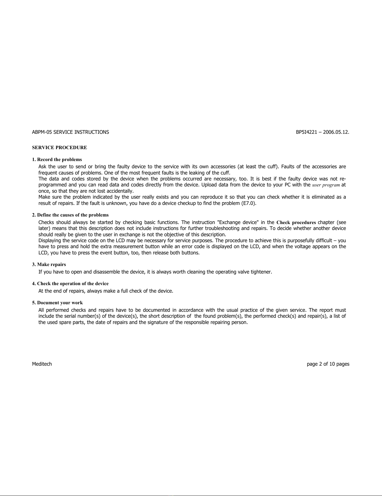
SERVICE PROCEDURE
1. Re ord the problems
Ask the user to send or bring the fau ty device to the service with its own accessories (at east the cuff). Fau ts of the accessories are
frequent causes of prob ems. One of the most frequent fau ts is the eaking of the cuff.
The data and codes stored by the device when the prob ems occurred are necessary, too. It is best if the fau ty device was not re-
programmed and you can read data and codes direct y from the device. Up oad data from the device to your PC with the user program at
once, so that they are not ost accidenta y.
Make sure the prob em indicated by the user rea y exists and you can reproduce it so that you can check whether it is e iminated as a
resu t of repairs. If the fau t is unknown, you have do a device checkup to find the prob em (E7.0).
2. Define the auses of the problems
Checks shou d a ways be started by checking basic functions. The instruction "Exchange device" in the Che k pro edures chapter (see
ater) means that this description does not inc ude instructions for further troub eshooting and repairs. To decide whether another device
shou d rea y be given to the user in exchange is not the objective of this description.
Disp aying the service code on the LCD may be necessary for service purposes. The procedure to achieve this is purposefu y difficu t – you
have to press and ho d the extra measurement button whi e an error code is disp ayed on the LCD, and when the vo tage appears on the
LCD, you have to press the event button, too, then re ease both buttons.
3. Make repairs
If you have to open and disassemb e the device, it is a ways worth c eaning the operating va ve tightener.
4. Che k the operation of the devi e
At the end of repairs, a ways make a fu check of the device.
5. Do ument your work
A performed checks and repairs have to be documented in accordance with the usua practice of the given service. The report must
inc ude the seria number(s) of the device(s), the short description of the found prob em(s), the performed check(s) and repair(s), a ist of
the used spare parts, the date of repairs and the signature of the responsib e repairing person.
Meditech page 2 of 10 pages
All manuals and user guides at all-guides.com
ABPM-05 SERVICE INSTRUCTIONS BP5I4221 – 2006.05.12.
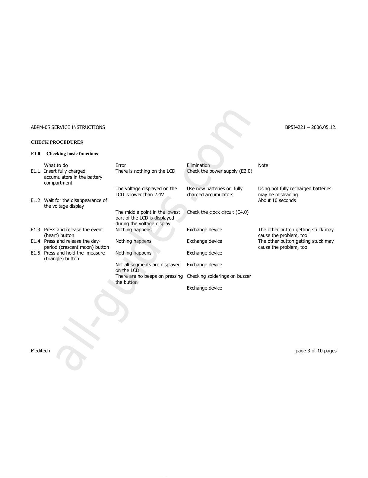
CHECK PROCEDURES
E1.0 Che king basi fun tions
What to do Error E imination Note
E1.1 Insert fu y charged
accumu ators in the battery
compartment
There is nothing on the LCD Check the power supp y (E2.0)
The vo tage disp ayed on the
LCD is ower than 2.4V
Use new batteries or fu y
charged accumu ators
Using not fu y recharged batteries
may be mis eading
E1.2 Wait for the disappearance of
the vo tage disp ay
About 10 seconds
The midd e point in the owest
part of the LCD is disp ayed
during the vo tage disp ay
Check the c ock circuit (E4.0)
E1.3 Press and re ease the event
(heart) button
Nothing happens Exchange device The other button getting stuck may
cause the prob em, too
E1.4 Press and re ease the day-
period (crescent moon) button
Nothing happens Exchange device The other button getting stuck may
cause the prob em, too
E1.5 Press and ho d the measure
(triang e) button
Nothing happens Exchange device
Not a segments are disp ayed
on the LCD
Exchange device
There are no beeps on pressing
the button
Checking so derings on buzzer
Exchange device
Meditech page 3 of 10 pages
All manuals and user guides at all-guides.com
all-guides.com
ABPM-05 SERVICE INSTRUCTIONS BP5I4221 – 2006.05.12.
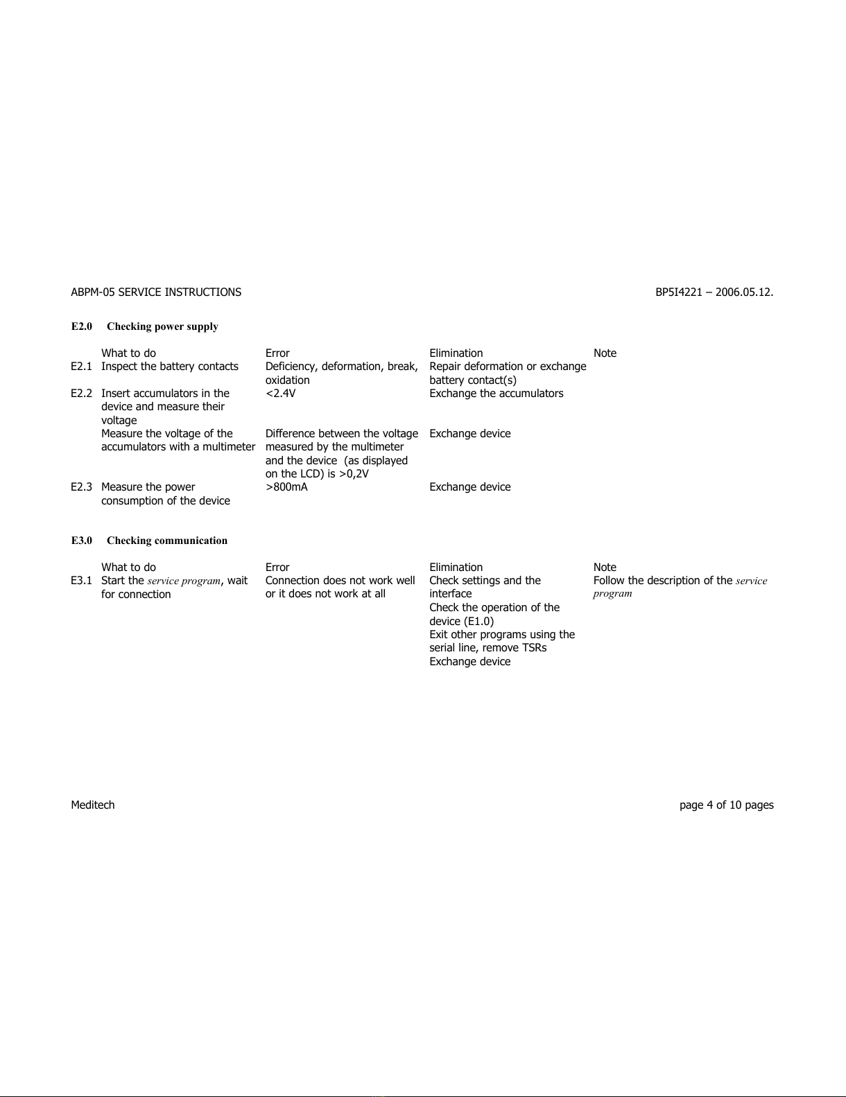
E2.0 Che king power supply
What to do Error E imination Note
E2.1 Inspect the battery contacts Deficiency, deformation, break,
oxidation
Repair deformation or exchange
battery contact(s)
E2.2 Insert accumu ators in the
device and measure their
vo tage
<2.4V Exchange the accumu ators
Measure the vo tage of the
accumu ators with a mu timeter
Difference between the vo tage
measured by the mu timeter
and the device (as disp ayed
on the LCD) is >0,2V
Exchange device
E2.3 Measure the power
consumption of the device
>800mA Exchange device
E3.0 Che king ommuni ation
What to do Error E imination Note
E3.1 Start the service program, wait
for connection
Connection does not work we
or it does not work at a
Check settings and the
interface
Fo ow the description of the service
program
Check the operation of the
device (E1.0)
Exit other programs using the
seria ine, remove TSRs
Exchange device
Meditech page 4 of 10 pages
All manuals and user guides at all-guides.com

ABPM-05 SERVICE INSTRUCTIONS BP5I4221 – 2006.05.12.
E4.0 Che king the lo k ir uit
What to do Error E imination Note
E4.1 Insert accumu ators in the
battery compartment wait at
east one hour, then set the
c ock of the device
On y if there have been no batteries
in the device for months or after
changing the button ce B1
supp ying the c ock IC
Vo tage disp ay does not
disappear and the crescent
moon is disp ayed
Exchange the button ce B1
supp ying the c ock IC
On y in case of automatic vo tage
disp ay after inserting the AA
batteries
E4.2 Read the date and time of the
device with the connection
function of the service program
Connection fai s Check connection (E3.0) The device stores the ast two bits
of the year on y and the program
ca cu ates the year according y
Wrong date or time Adjust the c ock of the PC ast
used for programming the
device or setting its c ock
E4.3 Adjust the c ock of your PC,
then write date and time to the
device with the time setting
function of the service program.
Read back the date and time
you just wrote
Wrong date or time Exchange device The fo owing points have to be
carried out on y if the prob em is
not ike y to have been caused by
the different settings of PCs
E4.4 Remove the accumu ators.
Re-insert them one day ater
and read the date and time of
the device
Wrong date or time Further check (E4.5). If it has
been done a ready, exchange
device
If there is no error, the E4.5 point
does not have to be carried out.
E4.5 Remove the accumu ators and
measure the vo tage of the
interna button ce . Repeat this
measurement one day ater
<1.1V Exchange the button ce and
repeat the who e c ock circuit
check (E4.0)
You do not have to necessari y wait
a fu day. It is recommended to
make a measurement from time to
time because the prob em usua y
turns out ear ier.
Exchange device
The date or time is wrong if it differs from the rea date and time by at east 3 minutes during one day. PC c ocks are usua y rather inaccurate, too!
Meditech page 5 of 10 pages
All manuals and user guides at all-guides.com

ABPM-05 SERVICE INSTRUCTIONS BP5I4221 – 2006.05.12.
E5.0 Che king the pneumati system / airtightness
This stage checks the device and/or the cuff. If you want to check the device, app y a f aw ess, norma size cuff around an approximate y 10-15
cm diameter cy inder with a rigid wa (artificia arm). When there is no pressure, there shou d be approximate y ha f an inch free room between
the cuff and the cy inder. A better so ution is to use a high thermocapacity, ½ iter air tank instead of the cuff.
What to do Error E imination Note
E5.1 Start the connection function of
the service program
It does not work or it sends an
error message
Check communication (E4.0)
E5.2 Start the airtightness test of the
service program
The device does not start
pumping in 10 seconds.
Check communication (E4.0)
Exchange device
E5.3 Wait. The device is pumping Pumping does not end in 1
minute
E iminate air eakage *Cuff
E5.4 Wait. 2 seconds after pumping,
the pressure shou d decrease to
about 250 mmHg
>270 mmHg Check and c ean operating
va ve tightener
Exchange device
<220 mmHg E iminate air eakage *Cuff
Exchange device
E5.5 Wait 1 minute. Leakage test >3 mmHg with air tank,
>6 mmHg if a cuff is used
E iminate air eakage *Cuff
E5.6 Wait. Def ation speed test >1600 ms with air tank,
>2400 ms if a cuff is used
Check and c ean operating
va ve tightener
Check both va ues disp ayed by the
service program
Safety va ve test. >5 sec with air tank,
>8 sec if a cuff is used
Check safety va ve.
E5.7 Start a new airtightness test
but this time with a free air
connector
The pressure disp ayed by the
device is higher than 2 mmHg
C ean or exchange the fi ter in
the tube to the cuff connector
Exchange device
*Cuff: oss of air may be caused by a wrong cuff, too.
Meditech page 6 of 10 pages
All manuals and user guides at all-guides.com

ABPM-05 SERVICE INSTRUCTIONS BP5I4221 – 2006.05.12.
E6.0 Che king pressure measurement
App y a f aw ess, norma size cuff around an approximate y 10-15 cm diameter cy inder with a rigid wa (artificia arm). When there is no
pressure, there shou d be approximate y ha f an inch free room between the cuff and the cy inder. A better so ution is to use a high
thermocapacity, ½ iter air tank instead of the cuff. Connect the ca ibrated pressure meter, an air pump to increase pressure, and a va ve to
decrease pressure.
What to do Error E imination Note
E6.1 *Decrease pressure to zero in
the connected pneumatic
system*
*This is very important! A ways
check with the ca ibrated pressure
meter, too*
E6.2 Start the connection point of
the service program
It does not work or sends an
error message
Check communication (E4.0)
E6.3 Start the pressure measuring
mode point of the service
program
The device does not show "v
0" and then " 0" on the LCD
Exchange device Wait for 5-10 seconds to see this
state
E6.4 Set 100 mmHg with the pump
and the va ve on your
ca ibrated pressure meter
Difference between pressure
meter and tested device is
>3 mmHg
Exchange device
E6.5 Set 200 mmHg Difference is >3 mmHg Exchange device
E6.6 Set 300 mmHg Difference is >3 mmHg Exchange device
E6.7 Exit pressure measuring mode The pressure does not
decrease, the device does not
switch back to the norma
mode
Check communication (E4.0)
and the operation of the va ves
Exchange device
Meditech page 7 of 10 pages
All manuals and user guides at all-guides.com
ABPM-05 SERVICE INSTRUCTIONS BP5I4221 – 2006.05.12.
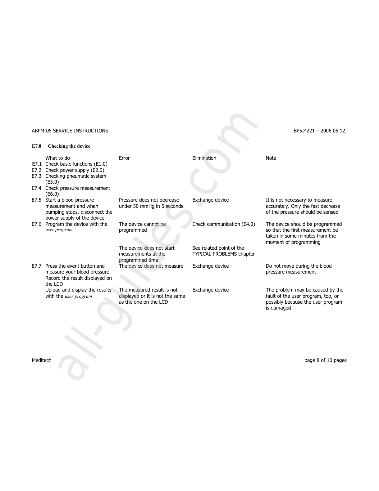
E7.0 Che king the devi e
What to do Error E imination Note
E7.1 Check basic functions (E1.0)
E7.2 Check power supp y (E2.0).
E7.3 Checking pneumatic system
(E5.0)
E7.4 Check pressure measurement
(E6.0)
E7.5 Start a b ood pressure
measurement and when
pumping stops, disconnect the
power supp y of the device
Pressure does not decrease
under 50 mmHg in 5 seconds
Exchange device It is not necessary to measure
accurate y. On y the fast decrease
of the pressure shou d be sensed
E7.6 Program the device with the
user program
The device cannot be
programmed
Check communication (E4.0) The device shou d be programmed
so that the first measurement be
taken in some minutes from the
moment of programming
The device does not start
measurements at the
programmed time
See re ated point of the
TYPICAL PROBLEMS chapter
E7.7 Press the event button and
measure your b ood pressure.
Record the resu t disp ayed on
the LCD
The device does not measure Exchange device Do not move during the b ood
pressure measurement
Up oad and disp ay the resu ts
with the user program
The measured resu t is not
disp ayed or it is not the same
as the one on the LCD
Exchange device The prob em may be caused by the
fau t of the user program, too, or
possib y because the user program
is damaged
Meditech page 8 of 10 pages
All manuals and user guides at all-guides.com
all-guides.com

ABPM-05 SERVICE INSTRUCTIONS BP5I4221 – 2006.05.12.
REPAIR METHODS
J1.0 Airtightness problems
1. If the cuff is eaking, exchange the cuff.
2. If the device is eaking, check and point out the cause. If the system is eaking heavi y, most frequent y tubes are disconnected or oose.
In case of minor eaking (5-20 mmHg in one minute), it is possib e that one of the rubber components is worn or the motor pump is
eaking. Separate sma sections of the pneumatic system after pumping up to ocate the eaking.
J2.0 Pushbuttons
1. If the buttons can be hard y operated or they get stuck, the reason is usua y the contamination of the knobs. Disassemb e the housing,
remove the button knobs, c ean the knobs, the buttons, and the housing around them.
2. The unre iab e operation of the buttons can be the resu t of a wrong assemb ing of the device /housing/. Pay attention to carefu
assemb ing after repairs.
Meditech page 9 of 10 pages
All manuals and user guides at all-guides.com
ABPM-05 SERVICE INSTRUCTIONS BP5I4221 – 2006.05.12.
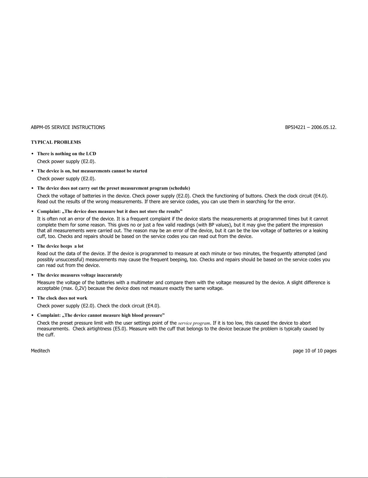
TYPICAL PROBLEMS
•There is nothing on the LCD
Check power supp y (E2.0).
•The devi e is on, but measurements annot be started
Check power supp y (E2.0).
•The devi e does not arry out the preset measurement program (s hedule)
Check the vo tage of batteries in the device. Check power supp y (E2.0). Check the functioning of buttons. Check the c ock circuit (E4.0).
Read out the resu ts of the wrong measurements. If there are service codes, you can use them in searching for the error.
•Complaint: „The devi e does measure but it does not store the results”
It is often not an error of the device. It is a frequent comp aint if the device starts the measurements at programmed times but it cannot
comp ete them for some reason. This gives no or just a few va id readings (with BP va ues), but it may give the patient the impression
that a measurements were carried out. The reason may be an error of the device, but it can be the ow vo tage of batteries or a eaking
cuff, too. Checks and repairs shou d be based on the service codes you can read out from the device.
•The devi e beeps a lot
Read out the data of the device. If the device is programmed to measure at each minute or two minutes, the frequent y attempted (and
possib y unsuccessfu ) measurements may cause the frequent beeping, too. Checks and repairs shou d be based on the service codes you
can read out from the device.
•The devi e measures voltage ina urately
Measure the vo tage of the batteries with a mu timeter and compare them with the vo tage measured by the device. A s ight difference is
acceptab e (max. 0,2V) because the device does not measure exact y the same vo tage.
•The lo k does not work
Check power supp y (E2.0). Check the c ock circuit (E4.0).
•Complaint: „The devi e annot measure high blood pressure”
Check the preset pressure imit with the user settings point of the service program. If it is too ow, this caused the device to abort
measurements. Check airtightness (E5.0). Measure with the cuff that be ongs to the device because the prob em is typica y caused by
the cuff.
Meditech page 10 of 10 pages
All manuals and user guides at all-guides.com
ABPM-05 SERVICE INSTRUCTIONS FOR HOSPITAL SERVICES BP5I4241 - 2006.05.12.
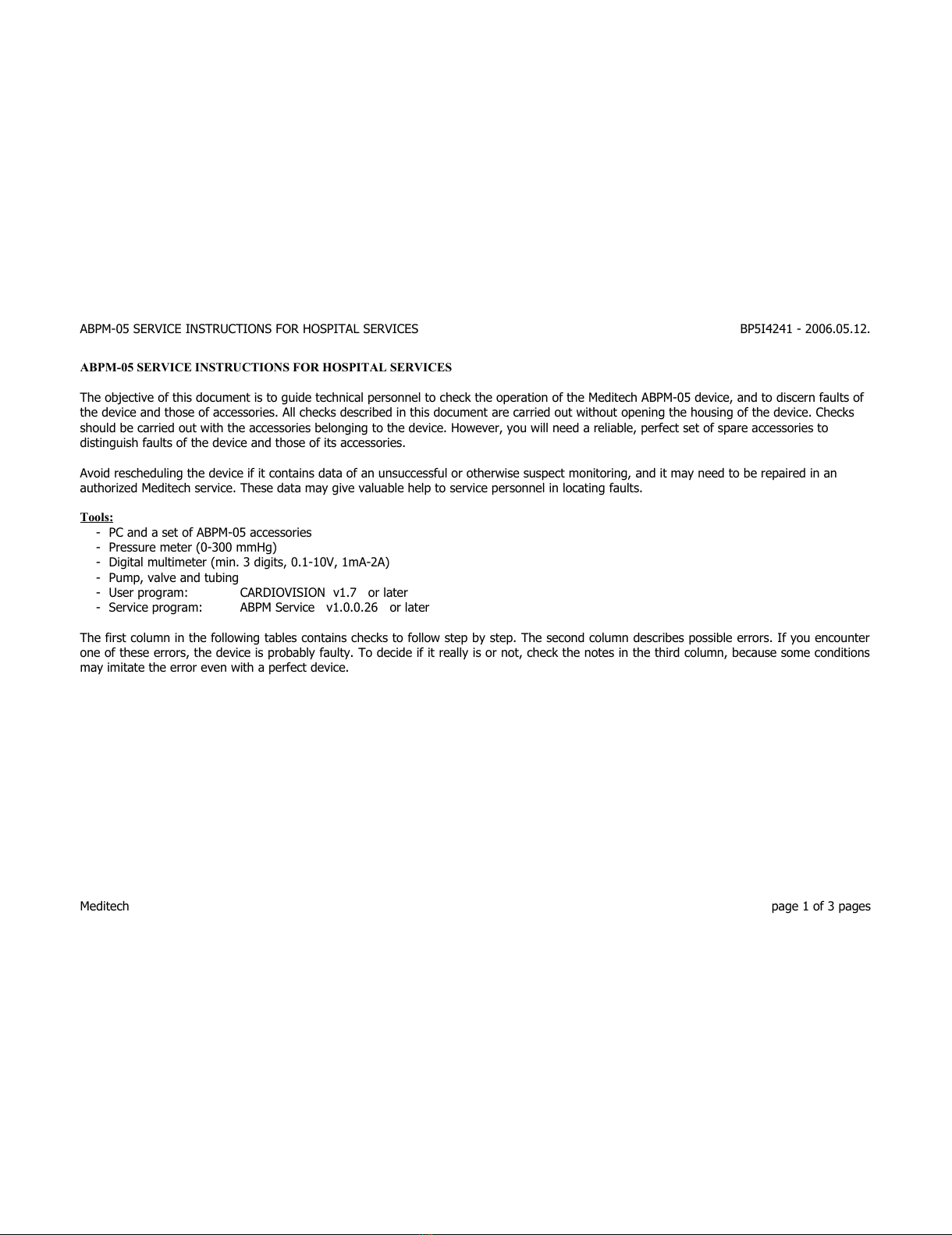
ABPM-05 SERVICE INSTRUCTIONS FOR HOSPITAL SERVICES
The obje tive of this do ument is to guide te hni al personnel to he k the operation of the Medite h ABPM-05 devi e, and to dis ern faults of
the devi e and those of a essories. All he ks des ribed in this do ument are arried out without opening the housing of the devi e. Che ks
should be arried out with the a essories belonging to the devi e. However, you will need a reliable, perfe t set of spare a essories to
distinguish faults of the devi e and those of its a essories.
Avoid res heduling the devi e if it ontains data of an unsu essful or otherwise suspe t monitoring, and it may need to be repaired in an
authorized Medite h servi e. These data may give valuable help to servi e personnel in lo ating faults.
Tools:
- PC and a set of ABPM-05 a essories
- Pressure meter (0-300 mmHg)
- Digital multimeter (min. 3 digits, 0.1-10V, 1mA-2A)
- Pump, valve and tubing
- User program: CARDIOVISION v1.7 or later
- Servi e program: ABPM Servi e v1.0.0.26 or later
The first olumn in the following tables ontains he ks to follow step by step. The se ond olumn des ribes possible errors. If you en ounter
one of these errors, the devi e is probably faulty. To de ide if it really is or not, he k the notes in the third olumn, be ause some onditions
may imitate the error even with a perfe t devi e.
Medite h page 1 of 3 pages
All manuals and user guides at all-guides.com

ABPM-05 SERVICE INSTRUCTIONS FOR HOSPITAL SERVICES BP5I4241 - 2006.05.12.
1. Check ng bas c funct ons
What to do Error Note
1.1 Insert 4 fully charged AA accumulators in
the battery compartment of the device. The LCD of the device remains blank or
the displayed voltage is lower than 2.4V. Accumulators may be faulty, too. Check them and repeat
this check with another set of accumulators.
Voltage display does not disappear
within 15 seconds. If there have been no accumulators in the device for
weeks, the backup button cell inside may have run down.
Wait an hour and recheck.
1.2 Check the voltage of the AAaccumulators
with a multimeter. The difference between the voltage
shown by the device and that measured
with the multimeter is >0.3V
The consumption of the device slightly decreasesthe
voltage of the accumulators as measured by the device.
1.3 Check the „stand-by” and the „pumping to
open air” current consumption of the
device. Then disconnect the multimeter
from the device.
Current consumption >5mA in stand-by
mode or >700mA while pumping to
open air (no cuff connected).
The internal resistance of the multimeter disturbs the
power supply of the device. If its internal resistance is
too high, the device cannot even switch to stand-by
mode.
1.4 Pressthe buttons and watch the LCD. There is no beep on pressing a button or
some LCDsegments are faulty. Disconnect the multimeter before this step because its
internal resistance may disturb the operation of the
device.
1.5 Connect the device to the PC,start the
service program, choose Connect. No connection. Time should be on the LCDbefore the connection.
The operation of the device is uncertain. Another PCprogram (TSR) may disturb the connection.
1.6 Set the clock of the device with the clock-
setting function of the service program.
Read it back and recheck after 24 hours.
The date is wrong or the clock is more
than 5 minutes late or fast. If you do not suspect that the clock is faulty, it is enough
to wait for a short time. Before setting the clock of the
device, check and adjust the PCcalendar and clock, too.
1.7 Program the device with the User program
and wait for a measurement. The device cannot be programmed or it
does not measure at the programmed
time.
Program the device only if you have not found any errors
so far, because error codes in the device are deleted by
the programming.
1.8 Pressthe event button, then the start
button and measure your blood pressure The device does not measure the blood
pressure. Apply cuff to your arm and do not move during the
measurement. Record the result as seen on the LCD.
1.9 Read out and check the event and the
reading with the User program. The measurement or the event is
missing or the result of the blood
pressure measurement is wrong.
Data are not stored if the data memory of the device is
already full.
Medite h page 2 of 3 pages
All manuals and user guides at all-guides.com

ABPM-05 SERVICE INSTRUCTIONS FOR HOSPITAL SERVICES BP5I4241 - 2006.05.12.
2. Check ng the pneumat c system, a rt ghtness and measurement accuracy
This stage checks the device and/or the cuff. If you want to check the device only, apply a flawless, normal size cuff around an approximately 10-15
cm diameter cylinder with a rigid wall (artificial arm). When there is no pressure, there should be approximately half an inch free room between the
cuff and the cylinder. A better solution is to use a high thermocapacity, ½ liter air tank instead of the cuff. Connect cuff or air tank to device.
Connect device to PC.
What to do Error Note
2.1 Start the airtightness test in the service
program.The device does not start pumping
within 15 seconds. Before the connection the time should be on the LCD.
2.2 Wait: the device is pumping. Pumping does not stop in 1 minute Leaking; may be caused by the fault of the cuff, too.
Wait: 2 seconds after pumping, the
pressure should decrease to about
250 mmHg.
Pressure is >270 mmHg or <220 mmHg
Wait 1 minute: leakage test. >3 mmHg with air tank
>6 mmHg with cuff around a cylinder Leaking may also be caused by the fault of the cuff.
Wait: deflation speed test. >1600 ms with air tank
>2400 ms with cuff around a cylinder Check both displayed deflation values.
Safety valve test. >5 sec with air tank
>8 sec with cuff around a cylinder
2.3 Disconnect cuff/air tank. Start another
airtightness test with free air connector. The pressure displayed by the device is
higher than 2 mmHg. Nothing should block or obstruct the pneumatic system.
2.4 The pressure in the pneumatic system
must be 0 before this step. Connect
external pressure meter, pump and valve
and check and ensure that pressure is 0.
Then start the pressure measuring point
of the service program.
The device does not switch to pressure
measuring mode in 15 seconds.
2.5 Set 100, 200 and 300 mmHg with the
pump and the valve on the external
pressure meter. Check LCDdisplay on
device.
Difference is >3 mmHg. When defining the error, take the inaccuracy of your own
pressure meter into consideration, too.
Medite h page 3 of 3 pages
All manuals and user guides at all-guides.com
all-guides.com
ABPM-05 service and error codes BP5I4202 – 2006.05.15.
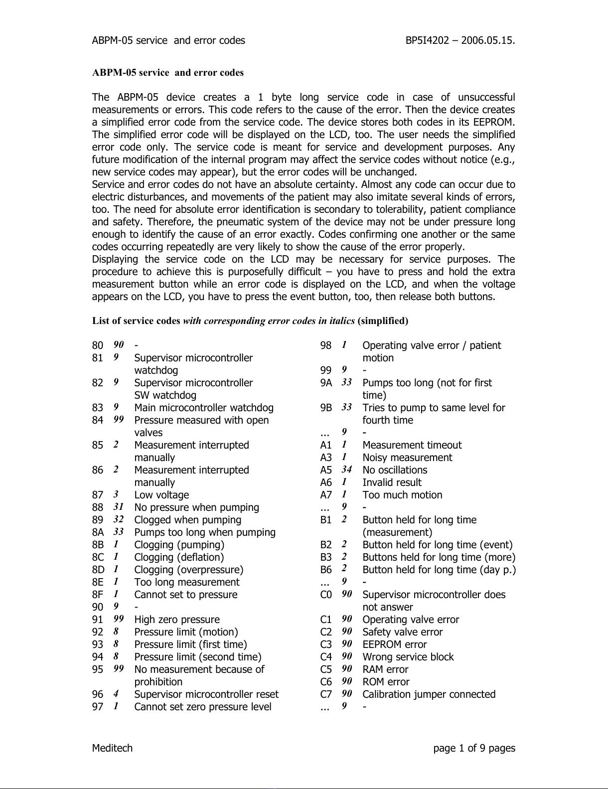
ABPM-05 service and error codes
The ABPM-05 device creates a 1 byte lon service code in case of unsuccessful
measurements or errors. This code refers to the cause of the error. Then the device creates
a simplified error code from the service code. The device stores both codes in its EEPROM.
The simplified error code will be displayed on the LCD, too. The user needs the simplified
error code only. The service code is meant for service and development purposes. Any
future modification of the internal pro ram may affect the service codes without notice (e. .,
new service codes may appear), but the error codes will be unchan ed.
Service and error codes do not have an absolute certainty. Almost any code can occur due to
electric disturbances, and movements of the patient may also imitate several kinds of errors,
too. The need for absolute error identification is secondary to tolerability, patient compliance
and safety. Therefore, the pneumatic system of the device may not be under pressure lon
enou h to identify the cause of an error exactly. Codes confirmin one another or the same
codes occurrin repeatedly are very likely to show the cause of the error properly.
Displayin the service code on the LCD may be necessary for service purposes. The
procedure to achieve this is purposefully difficult – you have to press and hold the extra
measurement button while an error code is displayed on the LCD, and when the volta e
appears on the LCD, you have to press the event button, too, then release both buttons.
List of service codes with corresponding error codes in italics (simplified)
80 90 -
81 9Supervisor microcontroller
watchdo
82 9Supervisor microcontroller
SW watchdo
83 9Main microcontroller watchdo
84 99 Pressure measured with open
valves
85 2Measurement interrupted
manually
86 2Measurement interrupted
manually
87 3Low volta e
88 31 No pressure when pumpin
89 32 Clo ed when pumpin
8A 33 Pumps too lon when pumpin
8B 1Clo in (pumpin )
8C 1Clo in (deflation)
8D 1Clo in (overpressure)
8E 1Too lon measurement
8F 1Cannot set to pressure
90 9-
91 99 Hi h zero pressure
92 8Pressure limit (motion)
93 8Pressure limit (first time)
94 8Pressure limit (second time)
95 99 No measurement because of
prohibition
96 4Supervisor microcontroller reset
97 1Cannot set zero pressure level
98 1Operatin valve error / patient
motion
99 9-
9A 33 Pumps too lon (not for first
time)
9B 33 Tries to pump to same level for
fourth time
... 9 -
A1 1Measurement timeout
A3 1Noisy measurement
A5 34 No oscillations
A6 1Invalid result
A7 1Too much motion
... 9 -
B1 2Button held for lon time
(measurement)
B2 2Button held for lon time (event)
B3
B6
2
2
Buttons held for lon time (more)
Button held for lon time (day p.)
... 9 -
C0 90 Supervisor microcontroller does
not answer
C1 90 Operatin valve error
C2 90 Safety valve error
C3 90 EEPROM error
C4 90 Wron service block
C5 90 RAM error
C6 90 ROM error
C7 90 Calibration jumper connected
... 9-
Meditech pa e 1 of 9 pa es
All manuals and user guides at all-guides.com

ABPM-05 service and error codes BP5I4202 – 2006.05.15.
List of error codes (simplified)
1aborted measurement 31 cuff missin or loose
2manually interrupted 32 cuff tubin clo ed
3battery rundown 33 cuff leakin or loose
4batteries chan ed 34 cuff not on arm
8pressure limit exceeded
temporary disturbance 0, device error
List of service codes with explanation with corresponding error codes in italics
The followin list contains service codes and correspondin error codes. Numbered lines in
the description part explain the actions that should be taken to identify and fix the causes of
the iven code. Actions to take are listed in the order of probability. First follow instruction
#1, if this does not help, proceed to instruction #2, etc. Repairs should be done in
authorized services only!
80 90 UNUSED SERVICE CODE
1. No repairs necessary. If encountered several times, exchan e device.
81 9The watchdo circuit of the supervisor microcontroller has si nalled.
Operation of the supervisor microcontroller was disturbed by some electric
si nal but it resumed automatically.
1. No repairs necessary.
2. If encountered several times, check the solderin of the supervisor
microcontroller. Exchan e device if necessary.
82 9The watchdo pro ram function of the supervisor microcontroller sensed an
error.
Data of the supervisor microcontroller show that the main microcontroller
has been in a iven state for too lon (10-150 sec, dependin on state).
1. No repairs necessary.
2. If encountered several times, check the solderin of the supervisor
microcontroller. Exchan e device if necessary.
83 9The watchdo circuit of the main microcontroller has si nalled.
Operation of the main microcontroller was disturbed by some electric si nal
but it resumed automatically.
1. No repairs necessary.
2. If encountered several times, check the solderin of the main and the
supervisor microcontroller, the ROM and RAM. Exchan e device if
necessary.
84 99 The device senses lastin pressure with open valves.
The value of the analo si nal measured at zero pressure has to fall
between iven limits. Either the pressure measurin circuit went wron or
the device was not able to open the valves and it is under pressure. The
latter case is hi hly improbable since the device has two valves controlled
by two different controllers. The device checks the pressure continuously
and if the above case persists, it does not start measurements. It tries to
open the valves every minute, stores service and error codes, and displays
error codes. The acoustic si nal relatin to the displayed error code cannot
be disabled.
1. Exchan e the device.
Meditech pa e 2 of 9 pa es
All manuals and user guides at all-guides.com
ABPM-05 service and error codes BP5I4202 – 2006.05.15.
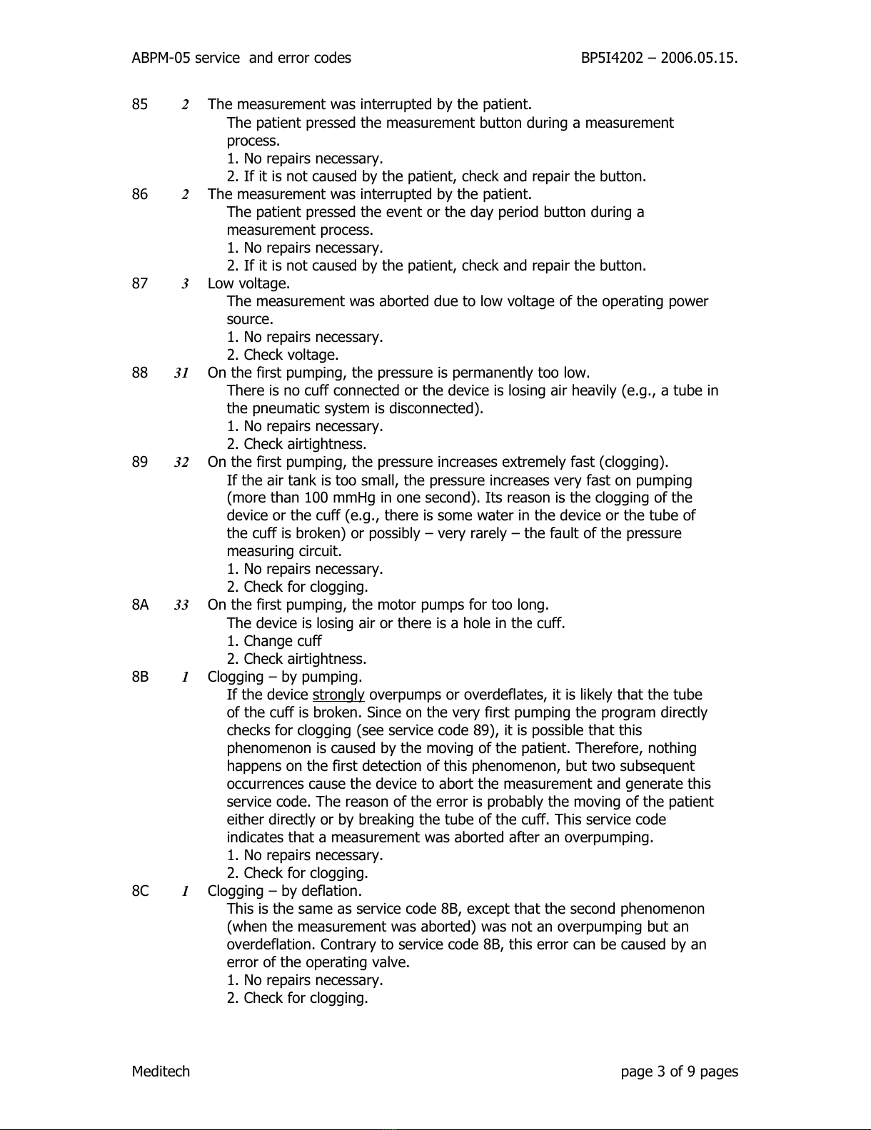
85 2The measurement was interrupted by the patient.
The patient pressed the measurement button durin a measurement
process.
1. No repairs necessary.
2. If it is not caused by the patient, check and repair the button.
86 2The measurement was interrupted by the patient.
The patient pressed the event or the day period button durin a
measurement process.
1. No repairs necessary.
2. If it is not caused by the patient, check and repair the button.
87 3Low volta e.
The measurement was aborted due to low volta e of the operatin power
source.
1. No repairs necessary.
2. Check volta e.
88 31 On the first pumpin , the pressure is permanently too low.
There is no cuff connected or the device is losin air heavily (e. ., a tube in
the pneumatic system is disconnected).
1. No repairs necessary.
2. Check airti htness.
89 32 On the first pumpin , the pressure increases extremely fast (clo in ).
If the air tank is too small, the pressure increases very fast on pumpin
(more than 100 mmH in one second). Its reason is the clo in of the
device or the cuff (e. ., there is some water in the device or the tube of
the cuff is broken) or possibly – very rarely – the fault of the pressure
measurin circuit.
1. No repairs necessary.
2. Check for clo in .
8A 33 On the first pumpin , the motor pumps for too lon .
The device is losin air or there is a hole in the cuff.
1. Chan e cuff
2. Check airti htness.
8B 1Clo in – by pumpin .
If the device stron ly overpumps or overdeflates, it is likely that the tube
of the cuff is broken. Since on the very first pumpin the pro ram directly
checks for clo in (see service code 89), it is possible that this
phenomenon is caused by the movin of the patient. Therefore, nothin
happens on the first detection of this phenomenon, but two subsequent
occurrences cause the device to abort the measurement and enerate this
service code. The reason of the error is probably the movin of the patient
either directly or by breakin the tube of the cuff. This service code
indicates that a measurement was aborted after an overpumpin .
1. No repairs necessary.
2. Check for clo in .
8C 1Clo in – by deflation.
This is the same as service code 8B, except that the second phenomenon
(when the measurement was aborted) was not an overpumpin but an
overdeflation. Contrary to service code 8B, this error can be caused by an
error of the operatin valve.
1. No repairs necessary.
2. Check for clo in .
Meditech pa e 3 of 9 pa es
All manuals and user guides at all-guides.com

ABPM-05 service and error codes BP5I4202 – 2006.05.15.
8D 1Clo in – overpressure.
There is overpressure in the device but it is probably the side effect of the
situation described at service code 8B. Probably, it was caused by the
movin of the patient or the breakin of the cuff tube.
1. No repairs necessary.
2. Check for clo in .
8E 1Measurin time safety check si nal.
The device checks measurin time at three levels (measurin al orithm,
safety check of the main microcontroller, supervisor microcontroller), and
this is the si nal from the middle level. Since it is not the first (al orithm)
level that si nalled, the reason is some error, probably a temporary
disturbance.
1. No repairs necessary. If encountered several times, exchan e device.
8F 1Device re ularly cannot step to required pressure level.
The error is probably caused by the movin of the patient or less probably
by some temporary clo in .
1. No repairs necessary.
2. Check for clo in .
90 9UNUSED SERVICE CODE
1. No repairs necessary. If encountered several times, exchan e device.
91 99 The zero pressure is too hi h when startin the measurement.
When startin the measurement, the value obtained on definin the zero
pressure is too hi h. The pressure measurin circuit went wron or the
valves are closed and the device is under pressure.
1. Exchan e the device.
92 8Pressure over the preset limit for too lon .
The movin of the patient increased the pressure over the preset pressure
limit for a prolon ed period. The error is directly caused by the movin of
the patient, but the ori inal reason is the improper settin of the pressure
limit. By increasin the preset limit, the error can be simply eliminated. The
overpressure can possibly be caused by the clo in of the cuff tube, too.
1. No repairs necessary.
93 8A pressure step over the pressure limit would be necessary for the
measurement.
The device tried to step to a pressure that the pressure limit does not
allow.
1. No repairs necessary.
94 8The device tried to pump above the pressure limit.
When pumpin to a pressure level, the pressure always decreases a little
after the motor pump stops. To ensure the accurate settin , the device
pumps a little over the required level. However, it cannot do so around the
preset pressure limit because overpressure may cause the measurement to
be aborted. Even in this case, it can usually reach the required pressure
with maximum two attempts. This service code means that the device
made several attempts but could not succeed. The service code may si nal
some minor leaka e, too.
1. No repairs necessary.
2. Check airti htness.
Meditech pa e 4 of 9 pa es
All manuals and user guides at all-guides.com
Other manuals for ABPM-05
3
Table of contents
Other Meditech Medical Equipment manuals


